
Related Manuals for Audio Technica ATW-T3201a


Summary of Contents for Audio Technica ATW-T3201a
- Page 1 3000 Series User Manual UHF Wireless Systems ATW-R3210 Receiver ATW-T3201 / ATW-T3201a Body-Pack Transmitter ATW-T3202 / ATW-T3202a Handheld Transmitter...
-
Page 2: Table Of Contents
Setting HPF (High-Pass Filter) ............... 21 Setting lock ....................21 Setting the function for the function button ..........21 Setting the mute mode (only for ATW-T3201 / ATW-T3201a) ....... 22 Setting the system-related functions ............22 How to attach the transmitter (ATW-T3201 / ATW-T3201a) ..24 Making connections (basic connections) ........24... -
Page 3: Introduction
Introduction Thank you for purchasing this Audio-Technica product. Before using the product, read through this user manual to ensure that you will use the product correctly. Please keep this manual for future reference. Important information Warning: For customers in the USA •... -
Page 4: Notes On Use
Notes on use • Be sure to read the user manual for any microphone or cable that you attach to the product. • Disconnect the AC adapter from the outlet when this product is not in use. • Turn off the power of this product before connecting or disconnecting cables. •... -
Page 5: Part Names And Functions
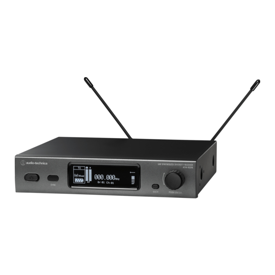
❺ ❶ Power button ( Use to turn the receiver on or off. ❷ IR sync window Use to IR SYNC with the transmitter (ATW-T3201, ATW-T3201a, ATW-T3202, ATW-T3202a). ❸ Display Displays the receiver state and setting menus. ❹ BACK button Press to take the display back one screen. - Page 6 Part names and functions Rear panel ❻ ❶ ❷ ❸ ❹ ❺ ❶ Antenna input jack Each jack supplies DC12 V to a connected antenna. Additionally other compatible accessories (sold separately) can be connected. ❷ Unbalanced output terminal (6.3 mm mono jack) ❸...
-
Page 7: Atw-T3201 / Atw-T3201A
Part names and functions ATW-T3201 / ATW-T3201a ❶ ❺ ❷ ❶ ❹ ❸ ❻ ❽ ❾ ❿ ⓮ ❼ ⓫ ⓬ ⓯ ⓭ ❶ ❼ Transmission antenna SYNC button Use to IR SYNC with the receiver (ATW-R3210). ❷ ❽ MUTE switch UP button Switches audio mute on and off. -
Page 8: Atw-T3202 / Atw-T3202A
Part names and functions ATW-T3202 / ATW-T3202a ❶ ❷ ❸ ❹ ❺ ❻ ❼ ❽ ❾ ❿ ⓫ ⓬ ⓭ ⓮ ❶ ❾ Interchangeable microphone capsule SYNC button ❷ Use to IR SYNC with the receiver (ATW-R3210). Display ❿ Power switch Shows the current status. -
Page 9: How To Insert Batteries
How to insert batteries ATW-T3201 / ATW-T3201a ATW-T3202 / ATW-T3202a Slide the battery cover latches down. Rotate the grip case of the battery compartment. Open the battery cover. • Put your finger on the hook of the battery cover and pull it to open the battery cover. -
Page 10: How To Attach And Detach The Interchangeable Microphone Capsule (Only For Atw-T3202 / Atw-T3202A)
How to attach and detach the interchangeable microphone capsule (only for ATW-T3202 / ATW-T3202a) How to attach Attach the microphone capsule to the body of the transmitter. Rotate the microphone capsule clockwise to tighten it. How to remove Rotate the microphone capsule counterclockwise to loosen it. Detach the microphone capsule from the body of the transmitter. -
Page 11: How To Read The Display
How to read the display ATW-R3210 Main screen ❶ ❷ ❸ ❹ ❺ ❻ VOCAL1 000.000 G 06 C 12 ❼ ❽ ❾ ❿ ⓫ ❶ ❼ Transmitter information display area Group indicator Information on the connected transmitter is displayed. Refer to ❽... - Page 12 How to read the display Level meter screen ❶ ❷ -74 dBm TX - RF PWR -40 -30 -24 -18 -15 -12 -10 -8 -6 -4 -2 0 +2 +4 +6 dBu ❸ ❹ ❺ ❻ ❶ ❹ RF power indicator (transmitter) Audio output indicator (receiver) ❷...
-
Page 13: Atw-T3201 / Atw-T3201A / Atw-T3202 / Atw-T3202A
How to read the display ATW-T3201 / ATW-T3201a / ATW-T3202 / ATW-T3202a The main screen is displayed when the power is switched on. If you press the UP/Down button on the main screen, the screen display is switched. ❶ ❻... -
Page 14: How To Operate
Position the IR sync windows of the receiver and transmitter so they face each other. ATW-T3201 / ATW-T3201a Set the operating frequency. Turn on the power switch of the transmitter (ATW-T3201 / ATW- T3201a / ATW-T3202 / ATW-T3202a). -
Page 15: Settings
Settings Various settings can be made from the menu screen shown on the ATW-T3201 / ATW-T3201a / ATW-T3202 / display. ATW-T3202a Press the SET button. • The menu screen appears. ATW-R3210 ATW-T3201 / ATW-T3201a ATW-T3202 / ATW-T3202a Press the control dial. -
Page 16: Setting Atw-R3210
Setting ATW-R3210 List of setting items Setting by group/channel From the menu screen, turn the control dial, select FREQUENCY MANUAL Set the operating frequency. [FREQUENCY] and then press the control dial. Gr/Ch NAME Set the channel name. AUDIO Set the audio output level. Select [Gr/Ch] and press the control dial. -
Page 17: Setting The Audio Output Level
Setting ATW-R3210 Setting the audio output level Setting transmitters via IR SYNC From the menu screen, turn the control dial, select [AUDIO] and This function allows you to make transmitter settings on the receiver then press the control dial. and then automatically configure the transmitter via IR SYNC. The following are the available settings and setting values: Turn the control dial to set the audio output level. -
Page 18: Setting The Squelch Level
Setting ATW-R3210 Setting the squelch level Setting the system-related functions Setting automatically Setting the lock From the menu screen, turn the control dial, select [SQUELCH] Set this function to prevent the receiver settings from being changed. and then press the control dial. •... - Page 19 Setting ATW-R3210 Setting user-defined scan groups Setting the backup frequency mode Aside from the ten preset groups, there are two additional user-defined If you set the backup frequency in advance, you can switch the scan groups: U1 and U2. Both U1 and U2 can be edited with up to 32 frequency of the transmitter and receiver with the transmitter.
- Page 20 Setting ATW-R3210 Setting the AF level meter on the main screen Resetting Switch the AF level meter on the main screen between [Receiver (Rx)] This returns the receiver settings to their factory defaults. and [Transmitter (Tx)]. From the menu screen, turn the control dial, select [UTILITIES] •...
-
Page 21: Setting Atw-T3201 / Atw-T3201A / Atw-T3202 / Atw-T3202A
Setting ATW-T3201 / ATW-T3201a / ATW-T3202 / ATW-T3202a List of setting items Setting by group/channel From the menu screen, press the UP/DOWN button to select FREQUENCY MANUAL Set the transmission frequency. [FREQUENCY], and then press the SET button. Gr/Ch NAME Set the channel name. -
Page 22: Adjusting The Gain
Setting ATW-T3201 / ATW-T3201a / ATW-T3202 / ATW-T3202a Adjusting the gain Setting lock From the menu screen, press the UP/DOWN button to select From the menu screen, press the UP/DOWN button to select [GAIN], and then press the SET button. -
Page 23: Setting The Mute Mode (Only For Atw-T3201 / Atw-T3201A)
Setting ATW-T3201 / ATW-T3201a / ATW-T3202 / ATW-T3202a Setting the mute mode (only for ATW-T3201 / Setting the indicator ATW-T3201a) The indicator LED can be turned [On] or [Off]. • The default setting is [On]. Set the function of the MUTE switch. - Page 24 Setting ATW-T3201 / ATW-T3201a / ATW-T3202 / ATW-T3202a Resetting This returns the transmitter settings to their factory defaults. From the menu screen, press the UP/DOWN button to select [UTILITIES], and then press the SET button. UTILITIES Press the UP/DOWN button to select [RESET] and press the SET button.
-
Page 25: How To Attach The Transmitter (Atw-T3201 / Atw-T3201A)
How to attach the transmitter (ATW-T3201 / ATW-T3201a) The ATW-T3201 / ATW-T3201a transmitter is equipped with a clip that can be used to attach the transmitter to a belt, etc. You can reverse the direction of the input connector by Pull both sides of the clip firmly to the outside to remove attaching the clip in the opposite direction. -
Page 26: Achieving Stable Reception
Achieving stable reception Low RF signal may result if there are obstructions between receiver antennas and transmitter(s). In such a case, reposition the antennas to get better reception. Use external antennas (sold separately) if the installation space is limited. Rack-mounting the receiver •... -
Page 27: Troubleshooting
Confirm that there isn't any other nearby wireless system using the same frequency p. 17 band. Adjust the squelch level. ATW-T3201 / ATW-T3201a / ATW-T3202 / ATW-T3202a Symptoms Causes and countermeasures Reference page The power can't be turned on. -
Page 28: Dimensions
Dimensions ATW-R3210 210.0 (Unit: mm) -
Page 29: Atw-T3201 / Atw-T3201A
Dimensions ATW-T3201 / ATW-T3201a (Unit: mm) ATW-T3202 / ATW-T3202a (Unit: mm) -
Page 30: Specifications
ATW-T3201 / ATW-T3201a: ±38 kHz (THD:10%) Maximum deviation ATW-T3202 / ATW-T3202a: ±36 kHz (THD:10%) ATW-T3201 / ATW-T3201a Mic input: 115 dB or higher (A-weighted), typical Dynamic range ATW-T3201 / ATW-T3201a Inst input: 112 dB or higher (A-weighted), typical ATW-T3202 / ATW-T3202a: 115 dB or higher (A-weighted), typical Total harmonic distortion 1.0 % or less (at 1 kHz, ±17.5 kHz deviation) -
Page 31: Atw-T3201 / Atw-T3201A
Specifications ATW-T3201 / ATW-T3201a RF output power High: 30 mW, Low: 10 mW (switchable), at 50 ohms Spurious emissions Following federal and national regulations Input connection Four pin locking connector Pin 1: GND Pin 2: INST INPUT Pin 3: MIC INPUT Pin 4: DC BIAS +5 V High-pass (low-freq. - Page 32 Audio-Technica Corporation 2-46-1 Nishi-naruse, Machida, Tokyo 194-8666, Japan www.audio-technica.com ©2023 Audio-Technica Corporation ver.1 2018.04.15 Global Support Contact: www.at-globalsupport.com 232416960-02-03 ver.3 2023.02.15...