Audio Technica 3000 Series User Manual
Wireless in-ear monitor system
Hide thumbs
Also See for 3000 Series:
- Quick start manual ,
- Installation and operation manual (125 pages) ,
- User manual (37 pages)
Table of Contents
Advertisement
Quick Links
Advertisement
Table of Contents

Related Manuals for Audio Technica 3000 Series


Summary of Contents for Audio Technica 3000 Series
- Page 1 3000 Series Wireless In-Ear Monitor System User Manual English...
- Page 2 Important information The product is intended for commercial use, not for general use. Warning: To prevent fire or shock hazard, do not expose this apparatus to rain or moisture. Caution: • Do not expose this apparatus to drips or splashes. •...
-
Page 3: Battery Caution
Battery caution: • Keep batteries out of the reach of children. • Observe correct polarity as marked. • Do not expose the battery to excessive heat such as sunshine, fire or the like. • Always consider the environmental issues and follow local regulations when disposing of batteries. •... -
Page 4: For Customers In The Usa
For customers in the USA FCC Notice Warning: This device complies with Part 15 of the FCC Rules. Operation is subject to the following two conditions: (1) This device may not cause harmful interference, and (2) this device must accept any interference received, including interference that may cause undesired operation. -
Page 5: For Customers In Canada
For customers in Canada ISED statement CAN RSS-Gen/CNR-Gen This device contains license-exempt transmitter(s)/receiver(s) that comply with Innovation, Science and Economic Development Canada’s license-exempt RSS(s). Operation is subject to the following two conditions: 1. This device may not cause interference. 2. This device must accept any interference, including interference that may cause undesired operation of the device. This device complies with RSS-102 radiation exposure limits set forth for an uncontrolled environment. -
Page 6: Notes On Use
Notes on use • Be sure to read the user manual for any microphone or cable that you attach to the product. • Unplug the AC adapter from the power outlet when not using the product. • Turn off the power of this product before connecting or disconnecting cables. •... - Page 7 About Hearing Damage WARNING! USE AS LOW A VOLUME AS POSSIBLE. PERMANENT HEARING DAMAGE CAN RESULT FROM USING THIS SYSTEM AT EXCESSIVE VOLUMES. For safe operation of this in-ear monitor system, do not listen at excessive sound pressure levels. Most national safety and health administrations have established guidelines for maximum time being exposed to sound pressure levels before hearing damage occurs.
-
Page 8: Maintenance
Maintenance • If the product becomes stained or covered with dust, be sure to disconnect the power plug before wiping it off with a dry and soft cloth. • Do not use benzene, thinner, or electrical contact cleaner, etc. Doing so may cause deformation, damage, or malfunction. -
Page 9: About This System
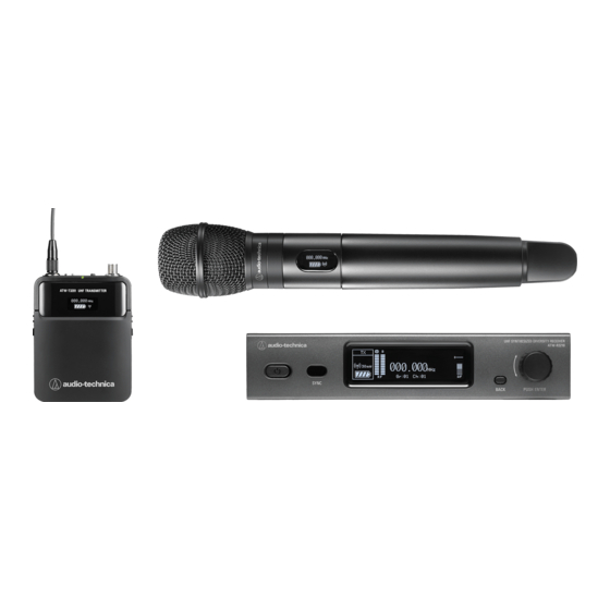
About this system This system (3000 Series Wireless In-Ear Monitor System) is designed to provide professional sound quality and functionality for all levels of live performance. It creates an optimal in-ear monitoring environment for live performance venue owners, system integrators, and performing musicians. A rack-mounted transmitter with front panel controls and large OLED display, a body-pack receiver with efficient headphone amplifier, and the ATH-E40 professional in-ear monitor headphones that create a balanced monitoring environment, are included in the package. -
Page 10: Part Names And Functions
Part names and functions ATW-T3205 (Stereo Transmitter) Front panel ❶ Power button Turns transmitter on or off. ❷ IR sync window Used for IR SYNC with receiver. ➌ Display Displays the transmitter status and settings. ❹ BACK button Press to take the display back one screen. Press and hold (about 2 seconds) on the main screen to toggle RF OFF (turning on while pressing and holding the BACK button will start the transmitter in RF OFF mode). -
Page 11: Rear Panel
Rear panel ❶ RF output jack Connect the included flexible UHF antenna. ❷ Balanced input jack (XLR 3-pin male) ➊ GND ➋ HOT ➌ COLD ➌ Balanced output jack (6.3 mm (1/4”) TRS female) ❹ Network interface By connecting to a PC via Ethernet, you can use the PC for monitoring and control. LAN: 100Base-TX ➎... - Page 12 ATW-R3250 (Stereo Receiver) ➊ Receiving antenna ➋ Function button Press to turn the screen back on if it shuts off. Press when the screen is lit to enter the audio setup screen. ➌ 3.5 mm (1/8”) headphone output jack ➍ ON/OFF volume knob Turns the power on or off.
- Page 13 ➎ Indicator LED that shows the status of the receiver. When unmuted: Solid green When muted: Solid red ➏ Display Shows the current status. If no buttons are pressed for a period of 30 seconds, the display will turn off. ➐...
- Page 14 ATH-E40 (Dynamic In-Ear Headphones) Also read the ATH-E40 user manual before use. ➊ A2DC connector plug ➋ Housing ➌ Cable adjustment slider ❹ 1.6 m (5.2') detachable cable ➎ Input plug (3.5 mm (1/8”) gold-plated stereo mini-plug (L-shaped)) ➏ LEFT/RIGHT (L/R) indicator ➐...
-
Page 15: Wearing The Headphones
Replacing the detachable cable The cable on the ATH-E40 is detachable. If there are signs of deterioration, replace the cable (sold separately). Do not detach the cable except when replacing it with a new cable. ➊ Headphone ➋ Cable How to detach the cable Hold the connector and pull straight out in the direction shown by the arrow. -
Page 16: System Configuration Examples
System configuration examples Basic connection example The mixer mixes the sound of vocals, guitars, and other instruments, transmits that sound from the transmitter to the receiver, and monitors it through headphones from the receiver. Loop out connection example (1) Use the loop out to send the band mix from the mixer and individual vocals, guitars, and other instrument sounds from the transmitter to the receiver, mix them at the receiver, and monitor them through headphones. - Page 17 Loop out connection example (2) Use the loop out to output the sound input to the transmitter to an external connected device (recorder, speakers, etc.). You can record simultaneously with your performance or output to floor speakers.
- Page 18 Rack-mounting (ATW-T3205) • Screws for rack-mounting the transmitter are not included. • Consider ventilation when rack-mounting to avoid heat building up in the rack.
- Page 19 Using the belt clip (ATW-R3250) The ATW-R3250 is equipped with a belt clip, so it can be attached to a belt, etc. Belt clip orientation The belt clip can be attached in the opposite direction. How to remove the belt clip To remove the belt clip from the receiver, pull both sides of the belt clip strongly outward.
- Page 20 Inserting batteries (ATW-R3250) Slide the battery cover latches down. Open the battery cover while holding the latches down.
- Page 21 Insert the batteries according to the plus (+) and minus (-) marks found inside the battery compartment.
-
Page 22: How To Read The Display
How to read the display ATW-T3205 ➊ Name display Displays the specified name. ➋ Frequency indicator Displays the specified frequency. ➌ RF OFF indicator Indicates when the RF output is turned off. ➍ AF level indicator Displays the level of the audio signal output from the transmitter to the receiver. When Mode is set to “Mono”... -
Page 23: Main Screen
ATW-R3250 Main screen ➊ AF level indicator Displays the level of the audio signal received by the receiver. For AF peak, “!” mark will appear. ➋ Frequency display Displays the specified frequency. ➌ Mute display ➍ Lock status display ➎ AF mode display ST: Stereo MX: Mix MB: Mono/Balance... -
Page 24: Level Meter Display
Level meter display This screen displays details of the RF meter and AF meter. User can use this to check detailed signal levels before playing, etc. ➊ RF mode display ST: Stereo MO: Mono 3KL: 3000Link ➋ RF level indicator Displays the reception status. -
Page 25: Switching Screen Display
Switching screen display The main screen is displayed when the receiver is turned on. Pressing the UP/DOWN button on the main screen switches the screen display (Frequency display → Name display → Group and channel display → Level meter display). Frequency display Name display Group and channel display... - Page 26 Network By connecting a transmitter to a Windows PC/Mac, you can monitor and control the status of the transmitters and the receivers using a dedicated software, Wireless Manager. What is Wireless Manager? Wireless Manager is software that supports the setup, control, and monitoring of compatible Audio-Technica wireless devices.
-
Page 27: Quick Start
Quick Start Basic flow of using this system Connect the included AC adapter to the transmitter and plug it into an outlet. Attach the included antenna to the transmitter's RF output jack. Connect a sound source such as a mixer output to the balanced input jack. •... - Page 28 Start playing. • Check that the AF level indicators on the transmitter and receiver are moving. Connect the headphones to the receiver and slowly turn up the volume. • Before connecting headphones, the volume on the receiver should be minimized. •...
-
Page 29: Useful Functions
Useful functions Performing RF scan Use RF scan to analyze the surrounding radio environment and set the available frequencies. There are three types of scans. Type of scan Description Group Scan Scan the frequencies in the group to set the available frequency channels. This is useful when finding available channels in a user group. - Page 30 When “Group” is selected, select the group to be scanned and press the SET button. • When “Full Group” is selected, this step is not required. Select the scan sensitivity from “Normal”, “Low” or “High” and press the SET button. Scan starts.
- Page 31 Synchronizing the last scanned data to the transmitter Press the SET button on the receiver's main screen. Press the UP/DOWN button to select “SCAN” and press the SET button. Select “Last Scan” and press the SET button. Press the SYNC button and place the IR sync window of the receiver so it is facing the IR sync window of the transmitter.
- Page 32 Performing IR SYNC Settings made on the transmitter can be synchronized with the receiver via IR SYNC. Press the control dial. The main menu screen appears. Turn the control dial to select “RX SYNC” and press the control dial. Turn the control dial to check the setting items to be synchronized with the receiver via IR SYNC. Move the cursor to “SYNC START”...
- Page 33 Using SYNC shortcut A shortcut allows immediate access to the “RX SYNC” screen, which synchronizes the transmitter's settings with the receiver's. Press and hold (for about 2 seconds) the control dial on the main screen. The “RX SYNC” screen appears.
- Page 34 Using the deploy function Instead of setting the frequency of each transmitter one by one, this function allows you to use RX SCAN DATA to set the frequency of all transmitters in the same network at once. This is useful when using multiple units at the same time. Set all transmitters to be used on the same network.
- Page 35 Using the cue mode Multiple frequencies can be saved as presets so that the receiver can switch between multiple frequencies. When operating multiple wireless systems, a single audio engineer can see audio being transmitted from multiple receivers while switching frequencies with a single receiver. •...
- Page 36 Adding a new preset Press the SET button on the cue mode main screen. Receiver is in standby for communication. Turn the transmitter's control dial to select "RX SYNC" and press the control dial. • Pressing and holding the control dial (about 2 seconds) will immediately display the "RX SYNC" screen. Move the cursor to "SYNC START"...
-
Page 37: Changing Presets
Changing presets Press the SET button on the cue mode main screen. Press the UP/DOWN button to select “Edit” and press the SET button. Select the preset you wish to change using the UP/DOWN button and press the SET button. Press the SYNC button. - Page 38 Deleting all presets Press the SET button on the cue mode main screen. Press the UP/DOWN button to select “Delete All” and press the SET button. The confirmation screen appears. Press the UP/DOWN button to select “Yes” and press the SET button. All presets are deleted.
-
Page 39: Basic Operation
Setting ATW-T3205 Basic operation Press the control dial. The main menu screen appears. Turn the control dial to select the item you wish to set. Press the control dial to open the settings menu of the selected item. • Press the BACK button to go back one screen. •... -
Page 40: Setting Manually
Setting the transmit frequency (FREQUENCY) Setting manually From the menu screen, turn the control dial, select “FREQUENCY” and then press the control dial. Select “MANUAL” and press the control dial. Turn the control dial to set the first 3 digits. When finished setting them, press the control dial. Turn the control dial to set the last 3 digits. - Page 41 Setting from RF scan results After RF scanning at the receiver, frequency setting can be made from the scan data synchronized via IR SYNC. See “Performing RF scan” (p.28) for more information on RF scanning. From the menu screen, turn the control dial, select “FREQUENCY” and then press the control dial. Select “RX SCAN DATA”...
- Page 42 3000 Link Mode Signals from the transmitter can be received by a 3000 Series receiver (sold separately) other than this system, and can be connected to speakers, amplifiers, recorders, etc. from that 3000 Series receiver.
- Page 43 Setting the RF power (RF POWER) From the menu screen, turn the control dial to select “RF POWER” and press the control dial. Turn the control dial to select “Low:10mW” / “High:50mW” and press the control dial. The setting is complete. Note •...
- Page 44 Turn the control dial to select “SYNC START” and press the control dial. - Communication is in standby. Thereafter, see “Performing IR SYNC” (p.31). • This setting can also be displayed by pressing and holding (for about 2 seconds) the control dial on the Note main screen.
- Page 45 Editing group/channel (Gr/Ch EDIT) Apart from the 18 preset groups, there are 6 user groups (U1-U6) where channels can be edited. In U1 to U6, you can edit up to 30 frequencies. • All channels are empty in the initial state. From the menu screen, turn the control dial, select “UTILITIES”...
- Page 46 Setting the main screen display (DISPLAY) Set items to be displayed prominently in the center of the main screen. From the menu screen, turn the control dial, select “UTILITIES” and then press the control dial. Turn the control dial to select “DISPLAY” and press the control dial. Turn the control dial to select “Frequency”...
- Page 47 Setting user access levels (ACCESS) From the menu screen, turn the control dial, select “UTILITIES” and then press the control dial. Turn the control dial, select “ACCESS” and then press the control dial. Turn the control dial to select “Free Tuning” / “User Group Only” and press the control dial. Item Description Free Tuning...
- Page 48 Checking the version of the transmitter (VERSION) From the menu screen, turn the control dial, select “UTILITIES”, and then press the control dial. Turn the control dial to select “VERSION”. Configuring the network (NETWORK) Connecting the transmitter to a PC allows monitoring and control via PC using a dedicated software (Wireless Manager). Item Description DEVICE ID...
- Page 49 Setting IP address (IP SETTING) From the menu screen, turn the control dial, select “NETWORK” and then press the control dial. Turn the control dial, select “IP SETTING” and then press the control dial. Select an item you want to set and press the control dial. Item Description IP Mode...
- Page 50 Configuring settings related to remote control (REMOTE CTRL) From the menu screen, turn the control dial, select “NETWORK” and then press the control dial. Turn the control dial, select “REMOTE CTRL” and then press the control dial. Select an item you wish to set and press the control dial. Item Description Port...
- Page 51 Configuring settings about log messages (SYSLOG) Set whether to send the log message to the Syslog server. From the menu screen, turn the control dial, select “NETWORK” and then press the control dial. Turn the control dial, select “SYSLOG” and then press the control dial. Turn the control dial to select “On”...
-
Page 52: Displaying Mac Address (Mac Address)
Configuring NTP settings (NTP) From the menu screen, turn the control dial, select “NETWORK” and then press the control dial. Turn the control dial, select “NTP” and then press the control dial. Select an item you wish to set and press the control dial. Item Description Set whether to enable or disable the NTP (Network Time Protocol). - Page 53 Setting ATW-R3250 Basic operation Press the SET button. The menu screen appears. Press the UP/DOWN button to select the item you wish to set. ➊ Selected menu item ➋ Current setting Press the SET button to display the settings screen for the selected item. •...
- Page 54 List of setting items Item Description FREQUENCY Set the operating frequency. NAME Set the channel name. SCAN Use RF scanning to analyze the surrounding radio environment and set the available frequencies. SQUELCH Set the squelch level. AUDIO Set the audio-related functions. UTILITIES Set the system-related functions.
- Page 55 Setting by group/channel From the menu screen, press the UP/DOWN button to select “FREQUENCY”, and then press the SET button. Select “Gr/Ch” and press SET button. Press the UP/DOWN button to set the group. After completing the setting, press the SET button. Press the UP/DOWN button to set the channel.
- Page 56 Performing the RF scan (SCAN) From the menu screen, press the UP/DOWN button to select “SCAN” and press the SET button. Select “Group Scan” / “Full Scan” / “Last Scan” and press the SET button. Follow the on-screen instructions. • See “Performing RF scan”...
- Page 57 Setting the audio mode (AUDIO MODE) The modes that can be selected vary depending on the RF mode setting. The modes that can be selected are as follows. When RF mode is set to “Stereo” Item Description Stereo The stereo input signal is output to L/R in stereo. Mix the input signal in stereo and output the same audio in L and R.
- Page 58 Setting the gain (GAIN) From the menu screen, press the UP/DOWN button to select “AUDIO” and press the SET button. Select “GAIN” and press the SET button. Press the UP/DOWN button to adjust, then press the SET button. The setting is complete. Setting the audio low-frequency sound quality (LOW EQ) The equalizer of this system is a shelving type.
- Page 59 Setting the output level to headphones (LIMITER) The factory default setting is “-30dB”. From the menu screen, press the UP/DOWN button to select “AUDIO” and press the SET button. Select “LIMITER” and press the SET button. Select “-30dB”, “-24dB”, “-18 dB “, “-12 dB “, “-6 dB“ or “Off” and press the SET button. The setting is complete.
- Page 60 Received in mono. 3000Link Used to receive signals from our separately sold 3000 Series transmitters. From the menu screen, press the UP/DOWN button to select “UTILITIES”, and then press the SET button. Select “RF MODE” and press the SET button.
- Page 61 Locking the audio output level (LVL LOCK) Lock the audio output level so that the volume cannot be adjusted. This is useful when you want to use a fixed volume without adjusting it repeatedly. From the menu screen, press the UP/DOWN button to select “UTILITIES”, and then press the SET button. Select “LVL LOCK”...
- Page 62 Using the cue mode (CUE MODE) From the menu screen, press the UP/DOWN button to select “UTILITIES”, and then press the SET button. Select “CUE MODE” and press the SET button. Cue mode is initiated. See “Using the cue mode” (p.34) for details on subsequent steps. Setting the type of battery to be used (BATTERY) From the menu screen, press the UP/DOWN button to select “UTILITIES”, and then press the SET button.
- Page 63 Setting the user access level (ACCESS) From the menu screen, press the UP/DOWN button to select “UTILITIES”, and then press the SET button. Select “ACCESS” and press the SET button. Select “Free” / “UserGroup” and press the SET button. Item Description Free No limit.
- Page 64 Check the receiver version (VERSION) From the menu screen, press the UP/DOWN button to select “UTILITIES”, and then press the SET button. Select “VERSION” and press the SET button.
-
Page 65: Troubleshooting
Troubleshooting ATW-T3205 ? The power can't be turned on • Check if the AC adapter is connected properly. ? There is no voice / The voice level is low • Check to see if the transmitter and receiver are on the same channel. •... - Page 66 ATW-R3250 ? The power can't be turned on • Confirm that batteries are in place. • Confirm that batteries are not depleted. • Confirm that batteries are inserted in the right direction. ? There is no voice / The voice level is low •...
- Page 67 Dimensions ATW-T3205...
- Page 68 ATW-R3250...
-
Page 69: Overall System Specifications
Specifications Overall system specifications Operating frequencies Band DF2: 470.125 to 607.875 MHz Band EG2: 580.000 to 713.850 MHz Minimum frequency step 25 kHz Modulation mode Nominal/Peak deviation ±34 kHz nominal / ±45 kHz peak Dynamic range >90 dB, A-weighted, typical Total harmonic distortion <0.2% (at 1 kHz, +4 dBu input) Operating range... - Page 70 ATW-R3250 Receiving system Antenna diversity Image rejection >80 dB, typical RF sensitivity 20 dBuV at 60 dBA S/N ratio (50 ohms termination) Headphone output jack 3.5 mm (1/8”) TRS stereo mini-jack Headphone output 40 mW (at 12 ohms) Low: 80 Hz / 160 Hz / 320 Hz / ±9 dB in 3 dB step High: 6 kHz / 8 kHz / 10 kHz / ±9 dB in 3 dB step Limiter Selectable: -30 dB to OFF (0 dB) in 6 dB steps...
- Page 71 株式会社オーディオテクニカ 〒194-8666 東京都町田市西成瀬2-46-1 www.audio-technica.co.jp Audio-Technica Corporation 2-46-1 Nishi-naruse, Machida, Tokyo 194-8666, Japan www.audio-technica.com ©2020 Audio-Technica Corporation Global Support Contact: www.at-globalsupport.com 232700590-02-01 ver.1 2022.05.15...