Table of Contents
Advertisement
Quick Links
INSTALLATION
MANUAL
CONTENTS
GENERAL . . . . . . . . . . . . . . . . . . . . . . . . . . . . . . . . . . . .4
SAFETY CONSIDERATIONS . . . . . . . . . . . . . . . . . . . . .4
INSPECTION . . . . . . . . . . . . . . . . . . . . . . . . . . . . . . . . . .4
REFERENCE . . . . . . . . . . . . . . . . . . . . . . . . . . . . . . . . . .4
RENEWAL PARTS . . . . . . . . . . . . . . . . . . . . . . . . . . . . .5
APPROVALS . . . . . . . . . . . . . . . . . . . . . . . . . . . . . . . . . .5
PRODUCT NOMENCLATURE . . . . . . . . . . . . . . . . . . . .6
INSTALLATION . . . . . . . . . . . . . . . . . . . . . . . . . . . . . . . .7
OPERATION . . . . . . . . . . . . . . . . . . . . . . . . . . . . . . . . .56
START-UP (COOLING) . . . . . . . . . . . . . . . . . . . . . . . . .63
START-UP (GAS HEAT) . . . . . . . . . . . . . . . . . . . . . . . .64
TROUBLESHOOTING . . . . . . . . . . . . . . . . . . . . . . . . . .67
See the following page for a complete Table of Contents.
NOTES, CAUTIONS AND WARNINGS
The installer should pay particular attention to the words:
NOTE, CAUTION, and WARNING. Notes are intended to
clarify or make the installation easier. Cautions are given
to prevent equipment damage. Warnings are given to
alert installer that personal injury and/or equipment dam-
age may result if installation procedure is not handled
properly.
CAUTION:
READ ALL SAFETY GUIDES BEFORE YOU
BEGIN TO INSTALL YOUR UNIT.
SAVE THIS MANUAL
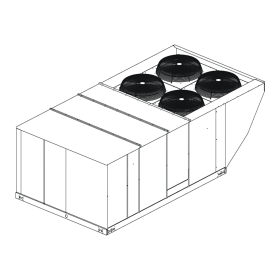
SUNLINE MAGNUM™
GAS/ELECTRIC SINGLE PACKAGE
AIR CONDITIONERS
MODELS: WJ180, 240 & 300
284812-YIM-D-1008
Advertisement
Table of Contents
Troubleshooting

Related Manuals for York SUNLINE MAGNUM WJ240


Summary of Contents for York SUNLINE MAGNUM WJ240
- Page 1 INSTALLATION SUNLINE MAGNUM™ MANUAL GAS/ELECTRIC SINGLE PACKAGE AIR CONDITIONERS CONTENTS GENERAL ........4 MODELS: WJ180, 240 &...
-
Page 2: Table Of Contents
284812-YIM-D-1008 TABLE OF CONTENTS GENERAL ........AIR BALANCE . - Page 3 284812-YIM-D-1008 PILOT CHECKOUT .......65 LIST OF TABLES BURNER INSTRUCTIONS ......65 Tbl.
-
Page 4: General
284812-YIM-D-1008 GENERAL YORK Model WJ units are either single package air conditioners equipped with optional factory installed FIRE OR EXPLOSION HAZARD electric heaters, or single package gas-fired central heating furnaces with cooling unit. Both are designed Failure to follow safety warnings exactly could for outdoor installation on a rooftop or slab. -
Page 5: Renewal Parts
284812-YIM-D-1008 RENEWAL PARTS ® Contact your local York Parts Distribution Center for authorized replacement parts. This product must be installed in strict compli- ance with the enclosed installation instructions APPROVALS and any applicable local, state, and national codes including, but not limited to, building, Design certified by CSA as follows: electrical, and mechanical codes. -
Page 6: Product Nomenclature
Simplicity IntelliComfort Controller 300 = 25 Ton Simplicity IntelliComfort Controller w/ModLinc York Commercial Comfort System (YCCS) Rtu Controller Heat Type and Nominal Heat Capacity Hot Gas Bypass (Standard on VAV, Optional on CV) C00 = Cooling Only. No field installed... -
Page 7: Installation
284812-YIM-D-1008 INSTALLATION In U.S.A.: • National Electrical Code ANSI/NFPA No. 70. INSTALLATION SAFETY INFORMATION: • National Fuel Gas Code Z223.1. Read these instructions before continuing this appli- • Gas-Fired Central Furnace Standard ANSI ance installation. This is an outdoor combination heat- Z21.47a. -
Page 8: Location
If a unit is to be installed on a roof curb or special frame appropriate angle iron frame. other than a YORK roof curb, gasketing must be applied to all surfaces that come in contact with the unit 6. Maintain level tolerance to 1/2 inch maximum underside. -
Page 9: Rigging And Handling
284812-YIM-D-1008 RIGGING AND HANDLING APPROXIMATE CENTER OF GRAVITY BACK CONDENSER Exercise care when moving the unit. Do not remove COIL END any packaging until the unit is near the place of installa- tion. Rig the unit by attaching chain or cable slings to the round lifting holes provided in the base rails. -
Page 10: Ductwork
284812-YIM-D-1008 FIXED OUTDOOR AIR INTAKE DAMPER This damper is shipped inside the return air compart- ment. It is completely assembled and ready for installa- Do not permit overhanging structures or shrubs tion. A damper baffle inside of the hood is adjustable to to obstruct outdoor air discharge outlet, com- provide variable amounts of outdoor air intake on units bustion air inlet or vent outlets. -
Page 11: Condensate Drain
284812-YIM-D-1008 COMPRESSORS Units are shipped with compressor mountings factory- adjusted and ready for operation. Do not loosen compressor mounting bolts. FILTERS Two-inch filters are supplied with each unit, but units can be converted easily to four-inch filters. Filters must always be installed ahead of the evaporator coil and must be kept clean or replaced with same size and type. -
Page 12: Typical Field Wiring
284812-YIM-D-1008 T H E R M O S T A T T E R M I N A L S UNIT CONTROL R C BOARD R H Y 1 Y 1 Y 2... -
Page 13: Thermostat
284812-YIM-D-1008 THERMOSTAT ada) and/or local codes. Refer to the Dimensions Figure 13 for installation location. If any of the wire sup- The room thermostat should be located on an inside wall plied with the unit must be replaced, replacement wire approximately 56 inches above the floor where it will not must be of the type shown on the wiring diagram and be subject to drafts, sun exposure or heat from electrical... -
Page 14: Optional Gas Heat
284812-YIM-D-1008 TABLE 3: ELECTRIC HEAT APPLICATION DATA NOMINAL VOLTAGE MINIMUM CFM UNIT SIZE HEATER SIZE 3-PHASE, 15 TON 20 TON 25 TON (KW) 60 HZ 208/230,460,575 4500 208/230,460,575 4500 208/230 5000 6000 7500 460,575 4500 208/230 5000 460,575 4500 OPTIONAL GAS HEAT These gas-fired heaters have aluminized-steel or All gas heaters are shipped from the factory equipped optional stainless steel, tubular heat exchangers with... -
Page 15: External Supply Connection External
284812-YIM-D-1008 the figures on page 15. All shaded items are field-sup- nections have been completed, open the main plied. shut-off valve admitting normal gas pressure to the mains. Check all joints for leaks with soap solution If gas supply line is routed through the unit's base or other material suitable for the purpose. -
Page 16: L.p. Units, Tanks And Piping
284812-YIM-D-1008 L.P./propane gas is an excellent solvent and special pipe compound must be used when assembling piping for this gas as it will quickly dissolve white lead or most standard commercial compounds. Shellac base compounds such as Rectorseal #5 are satisfactory for this type of gas. Check all connections for leaks when piping is com- pleted, using a soap solution. -
Page 17: Optional Economizer/Motorized Damper Rain Hood
284812-YIM-D-1008 Extreme care must be excercised in turning all setpoint, maximum, and minimum damper SLOTTED positioning adjustment screws to prevent twist- OPENINGS IN VENT AIR ACCESS PANEL ing them off. OUTLET HOODS Check that the damper blades move smoothly without binding;... -
Page 18: Indoor Air Quality Aq
284812-YIM-D-1008 INDOOR AIR QUALITY AQ DUCT STATIC PRESSURE TRANSDUCER A 0-5" WC pressure transducer, located in the control Indoor Air quality (indoor sensor input): Terminal AQ box compartment, is used to sense static (gauge) pres- accepts a +2 to +10 Vdc signal with respect to the sure in the supply air duct and convert this pressure (AQ1) terminal. -
Page 19: Factory-Installed Vfd
284812-YIM-D-1008 • OAT - analog input provided by a factory-installed set-point is adjustable between 0" WC and 5" WC with 10k-ohm, type 3 thermistor located in the outdoor air the default setting of 1.5" WC. compartment or mounted within the evaporator base The duct static high-limit set point is the maximum rail for units without the installed economizer option. -
Page 20: Manual Bypass
284812-YIM-D-1008 MANUAL BYPASS • an economizer actuator output signal (2-10 VDC) • a VFD speed reference output signal (2-10 VDC) An optional, factory-installed manual bypass switch available with factory-installed VFD can be found in the The use of shielded cable is recommended for the Blower Motor Access compartment and has the follow- above control wiring connections. -
Page 21: Optional Hot Gas Bypass (Hgbp)
284812-YIM-D-1008 wires are supplied with the unit and need to be con- and connected to the VAV board's "VAV BOX" termi- nected after the drive is installed. nal, must be field wired to the building's VAV boxes to ensure fully open dampers during heating operation. OPTIONAL HOT GAS BYPASS (HGBP) To allow for low cooling load operation, a direct-acting, Do not connect AC power to the T1, T2, T3... -
Page 22: Optional Reclaim Coil Piping Connection
284812-YIM-D-1008 Exhaust Air Adjustment Screw Exhaust Air LED Damper Min. Position Screw Indoor Air Quality Max. Adjustment Screw Indoor Air Quality Indoor Air Quality Min. Adjustment Screw Free Cool Free Cooling LED Economizer Enthalpy Set Point Adjustment Screw FIGURE 10 - HONEYWELL ECONOMIZER CONTROL W7212 OPTIONAL RECLAIM COIL PIPING CONNECTION The temperature required to make or break a brazed joint is sufficient to cause oxidation of copper unless an... -
Page 23: Four And Six Point Loads
284812-YIM-D-1008 FIGURE 11 - FOUR AND SIX POINT LOADS TABLE 6: FOUR AND SIX POINT LOADS Total 4 Point Loads (lbs) Unit Size Shipping Weight WJ180 Gas 2780 WJ240 Gas 3080 1003 1003 WJ300 Gas 3180 1036 1036 WJ180 Elec 2580 WJ240 Elec 2880... -
Page 24: Physical Data
284812-YIM-D-1008 TABLE 7: PHYSICAL DATA MODELS WJ 180 WJ 240 WJ 300 CENTRIFUGAL BLOWER (Dia. x Wd.) 15x15 18x15 EVAPORATOR BLOWER FAN MOTOR HP 5/7.5 10.0/7.5 15.0/7.5 ROWS DEEP EVAPORATOR FINS PER INCH COIL FACE AREA (Sq. Ft.) 20.5 PROPELLER DIA. (In.) (Each) CONDENSER FAN FAN MOTOR HP... -
Page 25: Wj Electrical Data W/O Powered Convenience Outlet - Std Drive Motor
284812-YIM-D-1008 TABLE 9: WJ ELECTRICAL DATA W/O POWERED CONVENIENCE OUTLET - STD DRIVE MOTOR COMPRESSORS HEATER OPTION MAX. MIN. FUSE/ MODEL OD FAN CONV BLOWER CIRCUIT (TON- VOLTAGE MOTORS OUTLET BRKR MOTOR AMPACITY MODEL STAGES AMPS NAGE) FLA EACH AMPS SIZE EACH EACH... - Page 26 284812-YIM-D-1008 TABLE 9: WJ ELECTRICAL DATA W/O POWERED CONVENIENCE OUTLET - STD DRIVE MOTOR (CONT.) COMPRESSORS HEATER OPTION MAX. MIN. FUSE/ MODEL OD FAN CONV BLOWER CIRCUIT (TON- VOLTAGE MOTORS OUTLET BRKR MOTOR AMPACITY MODEL STAGES AMPS NAGE) FLA EACH AMPS EACH EACH...
-
Page 27: Wj Electrical Data W/O Powered Convenience Outlet - High Static Drive Motor
284812-YIM-D-1008 TABLE 10: WJ ELECTRICAL DATA W/O POWERED CONVENIENCE OUTLET - HIGH STATIC DRIVE MOTOR COMPRESSORS HEATER OPTION MAX. MIN. FUSE/ MODEL OD FAN CONV BLOWER CIRCUIT (TON- VOLTAGE MOTORS OUTLET BRKR MOTOR AMPACITY MODEL STAGES AMPS NAGE) FLA EACH AMPS SIZE EACH... - Page 28 284812-YIM-D-1008 TABLE 10: WJ ELECTRICAL DATA W/O POWERED CONVENIENCE OUTLET - HIGH STATIC DRIVE MOTOR (CONT.) COMPRESSORS HEATER OPTION MAX. MIN. FUSE/ MODEL OD FAN CONV BLOWER CIRCUIT (TON- VOLTAGE MOTORS OUTLET BRKR MOTOR AMPACITY MODEL STAGES AMPS NAGE) FLA EACH AMPS EACH EACH...
-
Page 29: Wj Electrical Data W/O Powered Convenience Outlet - Low Static Drive
284812-YIM-D-1008 TABLE 11: WJ ELECTRICAL DATA W/O POWERED CONVENIENCE OUTLET - LOW STATIC DRIVE COMPRESSORS HEATER OPTION MAX. MIN. FUSE/ MODEL OD FAN CONV BLOWER CIRCUIT (TON- VOLTAGE MOTORS OUTLET BRKR MOTOR AMPACITY MODEL STAGES AMPS NAGE) FLA EACH AMPS SIZE EACH EACH... -
Page 30: Wj Electrical Data W/Powered Convenience Outlet - Std Drive Motor
284812-YIM-D-1008 TABLE 12: WJ ELECTRICAL DATA W/POWERED CONVENIENCE OUTLET - STD DRIVE MOTOR COMPRESSORS HEATER OPTION MAX. MIN. FUSE/ MODEL OD FAN CONV BLOWER CIRCUIT (TON- VOLTAGE MOTORS OUTLET BRKR MOTOR AMPACITY MODEL STAGES AMPS NAGE) FLA EACH AMPS SIZE EACH EACH (AMPS) - Page 31 284812-YIM-D-1008 TABLE 12: WJ ELECTRICAL DATA W/POWERED CONVENIENCE OUTLET - STD DRIVE MOTOR (CONT.) COMPRESSORS HEATER OPTION MAX. MIN. FUSE/ MODEL OD FAN CONV BLOWER CIRCUIT (TON- VOLTAGE MOTORS OUTLET BRKR MOTOR AMPACITY MODEL STAGES AMPS NAGE) FLA EACH AMPS EACH EACH SIZE...
-
Page 32: Pg. # 13 Wj Electrical Data W/Powered Convenience Outlet - High Static Drive Motor
284812-YIM-D-1008 TABLE 13: WJ ELECTRICAL DATA W/POWERED CONVENIENCE OUTLET - HIGH STATIC DRIVE MOTOR COMPRESSORS HEATER OPTION MAX. MIN. FUSE/ MODEL OD FAN CONV BLOWER CIRCUIT (TON- VOLTAGE MOTORS OUTLET BRKR MOTOR AMPACITY MODEL STAGES AMPS NAGE) FLA EACH AMPS SIZE EACH EACH... - Page 33 284812-YIM-D-1008 TABLE 13: WJ ELECTRICAL DATA W/POWERED CONVENIENCE OUTLET - HIGH STATIC DRIVE MOTOR (CONT.) COMPRESSORS HEATER OPTION MAX. MIN. FUSE/ MODEL OD FAN CONV BLOWER CIRCUIT (TON- VOLTAGE MOTORS OUTLET BRKR MOTOR AMPACITY MODEL STAGES AMPS NAGE) FLA EACH AMPS EACH EACH...
-
Page 34: Wj Electrical Data W/Powered Convenience Outlet - Low Static Drive
284812-YIM-D-1008 TABLE 14: WJ ELECTRICAL DATA W/POWERED CONVENIENCE OUTLET - LOW STATIC DRIVE COMPRESSORS HEATER OPTION MAX. MIN. FUSE/ MODEL OD FAN CONV BLOWER CIRCUIT (TON- VOLTAGE MOTORS OUTLET BRKR MOTOR AMPACITY MODEL STAGES AMPS NAGE) FLA EACH AMPS SIZE EACH EACH (AMPS) -
Page 35: Dimensions 15, 20 & 25 Ton
284812-YIM-D-1008 ECONOMIZER / MOTORIZED DAMPER FIXED OUTDOOR INTAKE AIR AND POWER EXHAUST RAIN HOODS (See detail Y) BLOWER MOTOR ACCESS (Location of BLOWER ACCESS Optional VFD Bypass) BLOWER (Location of COMPARTMENT/ Optional VFD) RECLAIM COIL 180-19/32 COMPRESSOR ACCESS CONNECTION (See detail X) ACCESS 52-5/8 DOT PLUG... -
Page 36: Rear View Dimensions
284812-YIM-D-1008 EVAPORATOR SECTION DOT PLUG (For pressure 40-3/8" drop reading) FILTER ACCESS SUPPLY RETURN COMPRESSOR OUTDOOR ACCESS 40-1/2" SUPPLY AIR 18-5/8" ACCESS 1" NPT FEMALE Dimensions listed are for side 27-3/4" COND. DRAIN CONNECTION 5-1/8" RETURN AIR duct flange openings; see ACCESS OUTDOOR AIR Field Accessories for Side... -
Page 37: Unit Clearances And Rain Hood Dimensions (15, 20 & 25 Ton)
284812-YIM-D-1008 NOTE: ELEC / ELEC Models: Units and ductwork are CLEARANCES approved for zero clearance to combustible material CLEARANCE LOCATION when equipped with electric heaters. 36” Front 24” (Less Economizer) Rear GAS / ELEC Models: A 1” clearance must be 49”... -
Page 38: Cfm, Static Pressure, And Power - Altitude And Temperature Corrections
284812-YIM-D-1008 CFM, STATIC PRESSURE, AND POWER - ALTI- order to use the indoor blower tables for high altitude applica- tions, certain corrections are necessary. TUDE AND TEMPERATURE CORRECTIONS A centrifugal fan is a "constant volume" device. This means The information below should be used to assist in application that, if the rpm remains constant, the CFM delivered is the of product when being applied at altitudes at or exceeding same regardless of the density of the air. -
Page 39: Altitude/Temperature Conversion Factor
284812-YIM-D-1008 Altitude/Temperature Conversion Factor 1.100 1.000 SEA LEVEL 1000 ft 2000 0.900 3000 4000 5000 0.800 6000 7000 8000 0.700 9000 10,000 0.600 TEMPERATURE (°F) FIGURE 16 - ALTITUDE/TEMPERATURE CONVERSION FACTOR Johnson Controls Unitary Products... -
Page 40: Wj180 Blower Performance - 15 Ton Standard Drive (Cooling Only) Downflow
284812-YIM-D-1008 TABLE 16: WJ180 BLOWER PERFORMANCE - 15 TON STANDARD DRIVE (COOLING ONLY) DOWNFLOW Blower Performance (Downflow Discharge) ESP CFM RPM KW BHP CFM RPM KW BHP CFM RPM KW BHP CFM RPM BHP CFM RPM BHP CFM RPM 6476 955 3.65 4.38 6183 922 3.24 3.89 5911 889 2.88 3.46 5695 857 2.61 3.14 5399 822 2.34... -
Page 41: Wj180 Blower Performance - 15 Ton Standard Drive (Gas Heat) Downflow
284812-YIM-D-1008 TABLE 17: WJ180 BLOWER PERFORMANCE - 15 TON STANDARD DRIVE (GAS HEAT) DOWNFLOW Blower Performance (Downflow Discharge) ESP CFM RPM KW BHP CFM RPM KW BHP CFM RPM KW BHP CFM RPM BHP CFM RPM BHP CFM RPM 6346 955 3.43 4.12 6059 922 3.05 3.66 5793 889 2.71 3.25 5581 857 2.46 2.95 5291 822 2.20... -
Page 42: Wj180 Blower Performance - 15 Ton High Static Drive (Cooling Only) Downflow
284812-YIM-D-1008 TABLE 18: WJ180 BLOWER PERFORMANCE - 15 TON HIGH STATIC DRIVE (COOLING ONLY) DOWNFLOW Blower Performance (Downflow Discharge) ESP CFM RPM KW BHP CFM RPM KW BHP CFM RPM KW BHP CFM RPM BHP CFM RPM BHP CFM RPM 7898 1120 5.88 7.18 7577 1082 5.29 6.45 7322 1044 4.78 5.83 7014 1005 4.21 5.13 6651 965 3.77... -
Page 43: Wj180 Blower Performance - 15 Ton High Static Drive (Gas Heat) Downflow
284812-YIM-D-1008 TABLE 19: WJ180 BLOWER PERFORMANCE - 15 TON HIGH STATIC DRIVE (GAS HEAT) DOWNFLOW Blower Performance (Downflow Discharge) ESP CFM RPM KW BHP CFM RPM KW BHP CFM RPM KW BHP CFM RPM BHP CFM RPM BHP CFM RPM 7740 1120 5.53 6.75 7425 1082 4.97 6.06 7176 1044 4.49 5.48 6874 1005 3.95 4.75 6518 965 3.55... -
Page 44: Wj240 Blower Performance - 20 Ton Standard Drive (Cooling Only) Downflow
284812-YIM-D-1008 TABLE 20: WJ240 BLOWER PERFORMANCE - 20 TON STANDARD DRIVE (COOLING ONLY) DOWNFLOW Blower Performance (Downflow Discharge) ESP CFM RPM KW BHP CFM RPM KW BHP CFM RPM KW BHP CFM RPM BHP CFM RPM BHP CFM RPM 9339 1014 7.07 8.63 8912 982 6.17 7.53 8487 949 5.55 6.77 8255 917 5.07 6.18 7835 885 4.63... -
Page 45: Wj240 Blower Performance - 20 Ton Standard Drive (Gas Heat) Downflow
284812-YIM-D-1008 TABLE 21: WJ240 BLOWER PERFORMANCE - 20 TON STANDARD DRIVE (GAS HEAT) DOWNFLOW Blower Performance (Downflow Discharge) ESP CFM RPM KW BHP CFM RPM KW BHP CFM RPM KW BHP CFM RPM BHP CFM RPM BHP CFM RPM 9152 1014 6.65 8.11 8734 982 5.80 7.08 8317 949 5.22 6.37 8090 917 4.76 5.81 7678 885 4.35... -
Page 46: Wj240 Blower Performance - 20 Ton High Static Drive (Cooling Only) Downflow
284812-YIM-D-1008 TABLE 22: WJ240 BLOWER PERFORMANCE - 20 TON HIGH STATIC DRIVE (COOLING ONLY) DOWNFLOW Blower Performance (Downflow Discharge) ESP CFM RPM KW CFM RPM KW BHP CFM RPM KW BHP CFM RPM KW BHP CFM RPM KW BHP CFM RPM KW BHP 9536 1035 7.43 9.07 9015 1001 6.63 8.09 8763 966 6.05 7.38 8384 932 5.21 6.35 9518 1073 7.83 9.55 9130 1036 7.19 8.77 8590 1002 6.25 7.62 8296 968 5.55 6.77 7917 933 4.90 5.97 9710 1107 8.51 10.39 9111 1073 7.48 9.13 8732 1038 6.71 8.19 8235 1005 5.96 7.27 7889 969 5.27 6.43 7468 934 4.73 5.77... -
Page 47: Wj240 Blower Performance - 20 Ton High Static Drive (Gas Heat) Downflow
284812-YIM-D-1008 TABLE 23: WJ240 BLOWER PERFORMANCE - 20 TON HIGH STATIC DRIVE (GAS HEAT) DOWNFLOW Blower Performance (Downflow Discharge) CFM RPM KW CFM RPM KW CFM RPM KW BHP CFM RPM KW BHP CFM RPM KW BHP CFM RPM KW BHP 9345 1035 6.99 8.53 8835 1001 6.23 7.60 8588 966 5.69 6.94 8216 932 4.89 5.97 9328 1073 7.36 8.98... -
Page 48: Wj300 Blower Performance - 25 Ton Standard Drive (Cooling Only) Downflow
284812-YIM-D-1008 TABLE 24: WJ300 BLOWER PERFORMANCE - 25 TON STANDARD DRIVE (COOLING ONLY) DOWNFLOW Blower Performance (Downflow Discharge) CFM RPM KW CFM RPM KW CFM RPM KW BHP CFM RPM KW BHP CFM RPM KW BHP CFM RPM KW BHP 11048 1103 10.04 12.25 10664 1069 9.15 11.16 10240 1035 8.23 10.05 9697 999 7.23 8.82 9401 963 6.56 8.00 8844 928 5.76 7.03 10704 1105 9.67 11.80 10299 1070 8.66 10.57 9866 1036 7.78 9.50 9301 1000 6.91 8.43 8985 964 6.26 7.63 8475 929 5.50 6.71 10377 1105 9.30 11.35 9922 1071 8.35 10.19 9461 1037 7.43 9.07 8909 1001 6.52 7.96 8533 966 5.86 7.15 8020 930 5.10 6.22... -
Page 49: Wj300 Blower Performance - 25 Ton Standard Drive (Gas Heat) Downflow
284812-YIM-D-1008 TABLE 25: WJ300 BLOWER PERFORMANCE - 25 TON STANDARD DRIVE (GAS HEAT) DOWNFLOW Blower Performance (Downflow Discharge) RPM KW BHP RPM KW BHP RPM KW BHP CFM RPM KW BHP CFM RPM KW BHP CFM RPM KW BHP 10827 1103 9.43 11.51 10451 1069 8.60 10.49 10035 1035 7.74 9.44 9503 999 6.80 8.29 9213 963 6.16 7.52 8667 928 5.42 6.61 10490 1105 9.09 11.09 10093 1070 8.14 9.93 9669 1036 7.31 8.93 9115 1000 6.49 7.92 8805 964 5.88 7.18 8306 929 5.17 6.31 10169 1105 8.74 10.67... -
Page 50: Wj300 Blower Performance - 25 Ton High Static Drive (Cooling Only) Downflow
284812-YIM-D-1008 TABLE 26: WJ300 BLOWER PERFORMANCE - 25 TON HIGH STATIC DRIVE (COOLING ONLY) DOWNFLOW Blower Performance (Downflow Discharge) ESP CFM RPM KW BHP CFM RPM KW BHP CFM RPM KW BHP CFM RPM KW BHP CFM RPM KW BHP CFM RPM KW BHP 11412 1139 11.02 13.45 10985 1110 10.05 12.26 10637 1075 9.20 11.23 10182 1040 8.16 9.96 0.6 11974 1216 12.94 15.79 11609 1180 11.94 14.57 11100 1142 10.63 12.97 10643 1111 9.66 11.78 10287 1076 8.70 10.62 9822 1040 7.82 9.55 0.8 11656 1216 12.56 15.32 11264 1180 11.44 13.96 10795 1144 10.20 12.44 10297 1111 9.26 11.30 9935 1076 8.39 10.23 9436 1041 7.41 9.04... -
Page 51: Wj300 Blower Performance - 25 Ton High Static Drive (Gas Heat) Downflow
284812-YIM-D-1008 TABLE 27: WJ300 BLOWER PERFORMANCE - 25 TON HIGH STATIC DRIVE (GAS HEAT) DOWNFLOW Blower Performance (Downflow Discharge) ESP CFM RPM KW CFM RPM KW CFM RPM KW CFM RPM KW BHP CFM RPM KW BHP CFM RPM KW BHP 11184 1139 10.36 12.64 10765 1110 9.45 11.53 10424 1075 8.65 10.55 9978 1040 7.67 9.36 0.6 11735 1216 12.16 14.84 11377 1180 11.22 13.69 10878 1142 9.99 12.20 10430 1111 9.08 11.08 10081 1076 8.18 9.98 9626 1040 7.35 8.97 0.8 11423 1216 11.80 14.40 11039 1180 10.75 13.12 10579 1144 9.59 11.70 10091 1111 8.71 10.62 9736 1076 7.88 9.62 9247 1041 6.97 8.50... -
Page 52: Static Resistances
284812-YIM-D-1008 TABLE 28: STATIC RESISTANCES RESISTANCE, IWG DESCRIPTION 15 TON 20 TON 25 TON 4500 6000 7500 6000 8000 9000 7500 8000 9300 WET INDOOR COIL 2 ROW RECLAIM COIL OPTIONS 3 ROW 18 KW 36 KW ELECTRIC HEAT OPTIONS 54 KW 72 KW ECONOMIZER OPTION... -
Page 53: Charging Chart - Wj180
284812-YIM-D-1008 15 Ton Charging Chart (ºF) Outdoor Temp 115º 105º 95º 85º 75º 65º Suction Pressure (psi) 1. Make sure that both condenser fans are running when charging. One fan may switch off at lower ambient temperatures making the chart above inaccurate. 2. -
Page 54: Phasing
With this information, the RPM for the PHASING supply air blower and the motor pulley adjustment YORK MODEL WJ units are properly phased at the (turns open) can be determined from the Blower Per- factory. Check for proper compressor rotation. If the formance Data Tables. -
Page 55: Air Balance
284812-YIM-D-1008 Note the following: To check the supply air CFM after the initial balancing has been completed: 1. The supply air CFM must be within the limitations 1. Remove the two 5/16" dot plugs from the blower shown in the Unit Application Data Table 1. motor and the filter access panels shown in Fig- ures 13 and 14. -
Page 56: Operation
284812-YIM-D-1008 OPERATION static pressure reaches or exceeds the high-limit set- point, then the supply fan motor will be shutdown. SEQUENCE OF OPERATIONS OVERVIEW For these units, the thermostat makes a circuit between "R" and "Y1" for the first stage of cooling. The call is passed to the unit control board (UCB), which If the unit is operated with the manual bypass then determines whether the requested operation is... -
Page 57: Economizer With Single Enthalpy Sensor
284812-YIM-D-1008 ECONOMIZER WITH SINGLE ENTHALPY SENSOR ECONOMIZER WITH OPTIONAL VAV OR INTELLI-COMFORT™ CONTROL When the room thermostat calls for "first-stage" cooling, The position of the outside air and return air dampers the low voltage control circuit from "R" to "G" and "Y1" is are controlled through a 2-10 VDC signal from the VAV completed. -
Page 58: Economizer With Optional Vav Blower With Power Exhaust
284812-YIM-D-1008 Upon de-energizing the final compressor, the blower the other compressor is inactive, the condenser fans will continue to run with the economizer damper in its will be de-energized. minimum position if in the Occupied mode; otherwise, LOW-PRESSURE LIMIT SWITCH the blower will stop following the elapse of the fan-off delay for cooling, and the economizer outdoor damper The low-pressure limit switch is not monitored during... -
Page 59: Safety Controls
284812-YIM-D-1008 blower is operated throughout the cycle. The 5-minute The ASCD is initiated on unit start-up and on any com- off period is necessary to defrost the indoor coil. pressor reset or lock-out. FLASH CODES Low ambient mode always begins with compressor operation. -
Page 60: Heating Operation Errors
284812-YIM-D-1008 The thermostat will cycle the electric heat to satisfy TABLE 31: LIMIT CONTROL SETTING the heating requirements of the conditioned space. TEMPERATURE TEMPERATURE All 240 & 480V heaters are provided with man- NOTE: UNIT HEATER LIMIT SWITCH VOLTAGE LIMIT SWITCH ual reset backup protection limits. -
Page 61: Gas Heating Sequence Of Operations
284812-YIM-D-1008 "GV1" to allow a flow of gas to only the first stage carry- TABLE 32: ELECTRIC HEAT ANTICIPATOR over tube. Only after the pilot flame has been ignited SETPOINTS and the presence of pilot flame detected at the "IC1" by SETTING, AMPS HEATER a signal sent back through the flame sensor is sparking... -
Page 62: Gas Heating Operation Errors
284812-YIM-D-1008 If voltage has been sensed at the GV for at least 15 seconds during the fan on delay for heating and GV REDUNDANT voltage or "W1" is lost, the indoor blower is forced on MAIN VALVE VALVE for the length of the fan off delay for heating. GAS MAIN SAFETY CONTROLS The unit control board monitors the temperature limit... -
Page 63: Flash Codes
284812-YIM-D-1008 5. Rollout Switch. FLASH CODES This switch is located above the main burners in The UCB will initiate a flash code associated with the control compartment, which in the event of a errors within the system. Refer to UNIT CONTROL sustained main burner rollout shuts off and locks BOARD FLASH CODES Table 36. -
Page 64: Operating Instructions
284812-YIM-D-1008 6. Check the unit supply air (CFM). See "CHECKING 1. Check the type of gas being supplied. Be sure that SUPPLY AIR CFM" on page 54. it is the same as listed on the unit nameplate. 7. Measure evaporator fan motor's amp draw. 2. -
Page 65: Manifold Gas Pressure Adjustment
284812-YIM-D-1008 2. To decrease the gas pressure, turn the adjusting screw counterclockwise. 3. To increase the gas pressure, turn the adjusting FIRE OR EXPLOSION HAZARD screw clockwise. Failure to follow the safety warning exactly could result In serious injury, death or property The correct manifold pressure for these fur- NOTE: damage. -
Page 66: Burner Air Shutter Adjustment
284812-YIM-D-1008 TABLE 35: GAS RATE - CUBIC FEET PER HOUR Seconds Size of Test Dial for One 1/2 cu. ft. 1 cu. ft. Rev. FIGURE 26 - TYPICAL FLAME APPEARANCE Burners are now accessible for service. Reverse the above procedure to replace the assem- blies. -
Page 67: Troubleshooting
284812-YIM-D-1008 TROUBLESHOOTING 3. If the supply air blower motor does not energize when the fan switch is set to ON, check that line voltage is being supplied to the contacts of the M3, COOLING TROUBLESHOOTING GUIDE contactor, and that the contactor is pulled in. For units with VFD, check that line voltage is being supplied to the M3-Auxiliary contacts. - Page 68 284812-YIM-D-1008 thermostat and the UCB, i.e. that the thermostat G the thermostat Y1 terminal, b) proper wiring terminal is connected to the G terminal of the UCB, between the room thermostat and the UCB, i.e. Y1 and for loose wiring. to Y1, Y2 to Y2, and c) loose wiring from the room thermostat to the UCB.
- Page 69 284812-YIM-D-1008 13. For units with economizers: If 24 volts is present at during free cooling if the call for the second stage the Y1 “OUT” terminal, check for 24 volts at the Y1 of cooling persists for 20 minutes. “ECON” terminal. If 24 volts is not present, check for loose wiring from the Y1 “OUT”...
- Page 70 284812-YIM-D-1008 not, press and release the ALARMS button on the the ALARMS button if the LED is not flashing an UCB. The UCB will flash the last five alarms on the alarm. LED. If the compressor is locked out, remove any call for cooling at the thermostat or by disconnect- 2.
-
Page 71: Gas Heat Troubleshooting Guide
284812-YIM-D-1008 call for cooling. This will reset any compressor lock 13. The UCB can be programmed to lock out compres- outs. sor operation during free cooling and in low ambi- ent conditions. These options are not enabled by While the above step will reset any lock outs, default. - Page 72 284812-YIM-D-1008 4. If M3 is not pulled in, check for 24 volts at the M3 coil. If 24 volts is present at M3 but M3 is not pulled in, replace the contactor. Label all wires prior to disconnection when ser- 5.
- Page 73 284812-YIM-D-1008 1. The draft motor has inherent protection. If the the (TDR) is open and must be replaced. If there is motor shell is hot to the touch, wait for the internal continuity, re-attach the wires.With the draft motor running, check for 24 volts at terminal 4 of (RW1-2) overload to reset.
-
Page 74: Unit Control Board Flash Codes
284812-YIM-D-1008 1. Adjust the pilot adjust screw on the gas valve as Main burners light but exhibit erratic flame characteris- described in “PILOT CHECKOUT” page 65. tics. 2. Check the supply pressure as described in “POST 1. Adjust air shutters as described in “BURNER AIR START CHECK LIST”... -
Page 75: Unit Control Board
284812-YIM-D-1008 TABLE 36: UNIT CONTROL BOARD FLASH CODES GREEN FLASH CODE DESCRIPTION On Steady This is a Control Failure 1 Flash Not Applicable 2 Flashes Flashing Control waiting ASCD 3 Flashes HPS1 Compressor Lockout 4 Flashes HPS2 Compressor Lockout 5 Flashes LPS1 Compressor Lockout 6 Flashes LPS2 Compressor Lockout... -
Page 76: Unit Control Board Option Setup
284812-YIM-D-1008 UNIT CONTROL BOARD OPTION SETUP • Press the COMM SETUP / SELECT button to tog- gle into the Heat Delay Setup, the green LED will turn off and the red LED for Heat Delay will turn on. OPTION BYTE SETUP •... -
Page 77: Optional Vav Control Board Flash Codes
284812-YIM-D-1008 OPTIONAL VAV CONTROL BOARD FLASH CODES TABLE 38: VAV CONTROL BOARD FLASH CODES FLASH CODE DESCRIPTION Flash codes are also utilized by the VAV add-on board to aid in troubleshooting optional VAV applications. On Steady Control Failure Flash codes are displayed by a red LED located near 1 Flash Not Applicable the center of the board using a short on/off cycle... - Page 78 284812-YIM-D-1008 Johnson Controls Unitary Products...
- Page 79 284812-YIM-D-1008 Johnson Controls Unitary Products...
- Page 80 Subject to change without notice. Printed in U.S.A. 284812-YIM-D-1008 Copyright © 2008 by Johnson Controls, Inc. All rights reserved. Supersedes: 284812-YIM-C-0708 Johnson Controls Unitary Products 5005 York Drive Norman, OK 73069...