Table of Contents
Advertisement
Quick Links
INSTALLATION INSTRUCTION
208/230/460 VOLT
MODELS ONLY
SAFETY CONSIDERATIONS
Due to system pressure, moving parts and electrical
components, installation and servicing of air conditioning
equipment can be hazardous. Only qualified, trained, service
personnel should install, repair, maintain or service this
equipment.
Observe all precautions in the literature, on labels and tags
accompanying the equipment whenever working on air
conditioning equipment. Be sure to follow all other safety
precautions that apply.
Wear safety glasses and work gloves, and follow all safety
codes. Use a quenching cloth and have a fire extinguisher
available for all brazing operations.
GENERAL
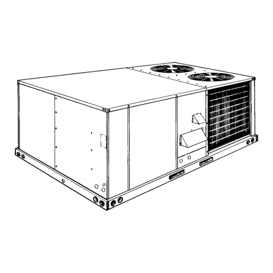
YORK Model DCG units are single package air conditioners
with gas heat designed for outdoor installation on a rooftop or
a slab.
The units are completely assembled on rigid, permanently
attached base rails. All piping, refrigerant charge, and electrical
wiring is factory installed and tested. The units require only
electric power and duct connections at the point of installation.
The gas-fired heaters have aluminized steel tubular heat
exchangers and spark ignition with proven pilot.
FOR YOUR SAFETY
If you smell gas:
1. Open windows.
2. Don't touch electrical switches; do not use
any phones in the area of the gas leak.
3. Extinguish any open flame.
4. Immediately call your gas supplier from another
location. Follow your gas supplier's
instructions.
5. If you cannot reach your gas supplier, call the
fire department.
Do not store or use gasoline or other flammable
vapors and liquids in the vicinity of this or any
other appliance
Installer should pay particular attention to the words: NOTE, CAUTION and WARNING . Notes are intended to clarify or make
the installation easier. Cautions are given to prevent equipment damage. Warnings are given to alert installer that personal injury
and/or equipment damage may result if installation procedure is not handled properly.
Supersedes: 530.18-N10Y (995)
MODELS D3CG090, 102, 120
FOR YOUR SAFETY
.
SUNLINE 2000™
GAS / ELECTRIC
SINGLE PACKAGE AIR CONDITIONERS
& D4CG090, 120, 150
INSPECTION
As soon as a unit is received, it should be inspected for possible
damage during transit. If damage is evident, the extent of the
damage should be noted on the carrier's freight bill. A separate
request for inspection by the carrier's agent should be made in
writing. Refer to Form 50.15-NM for additional information.
REFERENCE
Additional information on the design, installation, operation and
service of this equipment is available in the following reference
forms:
•
55.70-N1
•
55.70-N2
•
530.18-N3.2V
•
530.18-N3.8V
•
530.18-N3.9V
•
530.18-3.10V
•
530.18-N8.4V
•
530.18-N10.5V - Propane Conversion Accessory (USA)
•
530.18-N10.6V - High Altitude Accessory (Nat. Gas)
•
530.18-N10.7V - High Altitude Accessory (Propane)
•
690.15-N28V
Renewal Parts:
•
Refer to the Renewal Parts Manual for complete listing of
replacement parts on this equipment.
All forms referenced in this instruction may be ordered from:
Publications Distribution Center
Unitary Products Group
P.O. Box 1592, York, Pa. 17405
APPROVALS
Design certified by U.L. & CGA as follows:
1. For use as a forced air furnace with cooling unit.
2. For outdoor installation only.
3. For installation on combustible material.
4. For use with natural gas or propane gas.
THIS PRODUCT MUST BE INSTALLED IN STRICT COMPLIANCE
WITH THE ENCLOSED INSTALLATION INSTRUCTIONS AND ANY
APPLICABLE LOCAL, STATE, AND NATIONAL CODES
INCLUDING, BUT NOT LIMITED TO, BUILDING, ELECTRICAL,
AND MECHANICAL CODES.
INCORRECT INSTALLATION MAY CREATE A CONDITION
WHERE THE OPERATION OF THE PRODUCT COULD CAUSE
PERSONAL INJURY OR PROPERTY DAMAGE
530.18-N10Y (398)
208/230/575 VOLT
MODELS ONLY
- General Installation
- Pre-start & Post-start Check List
- Economizer Accessory
- Motorized Outdoor Air Damper Accy.
- Manual Outdoor Air Damper 0-35%
- Manual Outdoor Air Damper 0-100%
- Gas Piping Accessory
- Low Ambient Accessory
CAUTION
WARNING
035-16012
Advertisement
Table of Contents

Related Manuals for York Sunline 2000 D3CG090


Summary of Contents for York Sunline 2000 D3CG090
-
Page 1: General
- Economizer Accessory GENERAL • 530.18-N3.8V - Motorized Outdoor Air Damper Accy. • YORK Model DCG units are single package air conditioners 530.18-N3.9V - Manual Outdoor Air Damper 0-35% • with gas heat designed for outdoor installation on a rooftop or 530.18-3.10V - Manual Outdoor Air Damper 0-100% •... -
Page 2: Table Of Contents
530.18-N10Y TABLE OF CONTENTS General ................1 MAINTENANCE & TROUBLESHOOTING Inspection................1 Normal Maintenance............18 Reference ................1 Cleaning Flue Passages and Heating Elements ....18 Approvals ................1 Troubleshooting ..............19 Nomenclature............... 2 Replacement Parts ............20 INSTALLATION TABLES Limitations ................ -
Page 3: Installation
CAUTION: If a unit is to be installed on a roof curb or In U.S.A.: special frame other than a YORK roof curb, gasketing must be applied to all surfaces that 1. National Electrical Code ANSI/NFPA No. 70. -
Page 4: Condensate Drain
530.18-N10Y DUCTWORK SERVICE ACCESS Access to all serviceable components is provided by the Ductwork should be designed and sized according to the methods following removable panels: in Manual Q of the Air Conditioning Contractors of America (ACCA). • Compressor compartment A closed return duct system shall be used. -
Page 5: Combustion Discharge
530.18-N10Y *24 Volt Thermostat 2TH04701024 or (2TH04701524 w/Subbase 2TB04700224) FIG. 3 - TYPICAL FIELD WIRING TABLE 2 - GAS HEAT APPLICATION DATA TABLE 3 - PIPE SIZING Temp. Rise °F Nominal Iron Pipe Size Input Output Available on Gas Rate Length in Feet At Full Input Capacity,... -
Page 6: L.p. Units, Tanks And Piping
530.18-N10Y FIG. 5 - BOTTOM SUPPLY CONNECTION FIG. 4 - EXTERNAL SUPPLY CONNECTION EXTERNAL SHUT-OFF EXTERNAL SHUT-OFF L.P. UNITS, TANKS AND PIPING OPTIONAL ECONOMIZER The following procedure should be used when assembling an All gas heat units are shipped from the factory equipped for economizer rain hood onto a unit. - Page 7 530.18-N10Y b) Attach two filter guide angles to the inside of each side 5. Insert two (2) 1" filters into the center of the hood, coming plate using 3 screws for each angle. Note the hole to rest in the center filter support at the back of the hood. locations on the angles for proper positioning when Press filters up against the filter guide angles on the side attaching them on the side plates.
-
Page 8: Physical Data
530.18-N10Y FIG. 8 - ENTHALPY SETPOINT ADJUSTMENT TABLE 4 - PHYSICAL DATA WEIGHTS (LBS) MODEL 7-1/2 Ton 1040 CENTRIFUGAL BLOWER (Dia. x Wd. in.) 12 x 12 12 x 12 15 X 12 15 x 12 8-1/2 Ton 1125 BASIC UNIT EVAPORATOR 10 Ton 1180... -
Page 9: Economizer
530.18-N10Y RETURN AIR SUPPLY AIR CONDENSER AIR OUTDOOR AIR (Economizer) DUCT COVERS - Units are shipped with all air duct openings covered. For side duct applications; 1. Remove and discard the supply and return air duct covers. 2. Connect ductwork to duct flanges on the rear of the unit. -
Page 10: Point Loads
530.18-N10Y DETAIL "Y" (Unit With Economizer Rain Hood) CLEARANCES Locate unit so that the vent air outlet hood is at least: • Three (3) feet above any forced air inlet located within 10 horizontal feet (excluding those Front 24" integral to the unit). 12"... -
Page 11: Supply Air Blower Perf. 7-1/2 - 10 Ton
530.18-N10Y TABLE 6 - SUPPLY AIR BLOWER PERFORMANCE (7-1/2, 8-1/2 & 10 TON) MODEL DCG090 - (SIDE DUCT APPLICATIONS) BLOWER 2250 2550 3000 3400 3750 SPEED, 0.83 1.16 1.08 0.66 1.27 1.18 0.37 1.45 1.35 0.08 1.65 1.54 1025 0.98 1.21 1.13 0.82... -
Page 12: Supply Air Blower Perf. 12-1/2 Ton
530.18-N10Y TABLE 7 - SUPPLY AIR BLOWER PERFORMANCE (12-1/2 TON) MODEL DCG150 - (SIDE DUCT APPLICATIONS) BLOWER SPEED, 4000 4500 5000 5500 6000 1.00 2.14 2.00 0.70 2.43 2.27 0.40 2.72 2.54 0.11 3.03 2.83 1000 1.20 2.33 2.17 0.93 2.62 2.45 0.65... -
Page 13: Operation
530.18-N10Y TABLE 10 - ELECTRICAL DATA SUPPLY TOTAL OUTDOOR MAX. COMPRESSOR UNIT MAX. BLOWER HACR (#1 and #2) AMPACITY, POWER MOTOR, FUSE MOTOR, MODEL BREAKER AMPS SUPPLY (#1 & #2) SIZE SIZE, AMPS AMPS EACH EACH EACH 208/230-3-60 14.1 — -—... -
Page 14: Safety Controls (Heating)
530.18-N10Y The “TH1" closes, the draft motor control ”DMC or ETD" is 2. Centrifugal Switch (CS). If the draft motor should fail, the energized. The “DMC” power contact closes which energizes centrifugal switch attached to the shaft of the motor pre- the line voltage draft motor. -
Page 15: Operating Instructions
530.18-N10Y START-UP OPERATING INSTRUCTIONS Adjust as follows: CAUTION: This furnace is equipped with an intermittent pilot 1. Remove the cap on the regulator. It’s located next to the and automatic re-ignition system. DO NOT attempt push-on electrical terminals. to manually light the pilot. 2. -
Page 16: Burner Air Shutter Adjustment
530.18-N10Y obtain the desired supply air CFM. Tighten belts enough to PRE-START CHECK LIST prevent slipping. but do not over tighten. Belt deflection should Complete the following checks before starting the unit. be between 1/4" and 1/2" per foot. Refer to the Blower Motor And Drive Data table. -
Page 17: Adjustment Of Temperature Rise
530.18-N10Y ADJUSTMENT OF TEMPERATURE RISE TABLE 13 - GAS RATE - CUBIC FEET PER HOUR Seconds Size of Test Dial The temperature rise (or temperature difference between the for One return air and the heated air from the furnace) must lie within 1/2 cu. -
Page 18: Normal Maintenance
530.18-N10Y MAINTENANCE NORMAL MAINTENANCE CLEANING FLUE PASSAGES AND HEATING ELEMENTS CAUTION: Prior to any of the following maintenance proce- dures, shut off all power to the unit to prevent With proper combustion adjustment the heating element of a personal injury. gas fired furnace will seldom need cleaning. -
Page 19: Troubleshooting
530.18-N10Y TROUBLESHOOTING WARNING: Troubleshooting of components necessarily re- 2. The supply air blower operates but the draft motor does not when the room thermostat is set to call for heat and the fan quires opening the electrical control box with the switch in the “ON”... -
Page 20: Replacement Parts
PROPERTY DAMAGE. CONSULT A QUALIFIED INSTALLER, SERVICE AGENCY OR YOUR LOCAL GAS SUPPLIER FOR INFORMATION OR ASSISTANCE. Unitary Products Group P.O. Box 1592, York, Pennsylvania USA 17405-1592 Subject to change without notice. Printed in U.S.A Copyright © by York International Corporation 1997. All Rights Reserved. 530.18-N10Y SHU 10M 995 1.10 Code: SBY...