
Related Manuals for Fluke TIP900


Summary of Contents for Fluke TIP900
- Page 1 TIP900 Wallboard Temperature Imaging & Profiling System Operating Instructions Rev. E1 Feb 2016 59611...
- Page 2 Fluke Process Instruments China Beijing, China Tel: +8610 6438 4691 info@flukeprocessinstruments.cn Worldwide Service Fluke Process Instruments offers services, including repair and calibration. For more information, contact your local office or e-mail support@flukeprocessinstruments.com www.flukeprocessinstruments.com © Fluke Process Instruments Specifications subject to change without notice.
- Page 3 ARRANTY The manufacturer warrants this instrument to be free from defects in material and workmanship under normal use and service for the period of two years from date of purchase. This warranty extends only to the original purchaser. This warranty shall not apply to fuses, batteries, or any product which has been subject to misuse, neglect, accident, or abnormal conditions of operation.
-
Page 4: Table Of Contents
REREQUISITES IMITATIONS ENERAL NFORMATION 5.2 O TIP900 SW..........40 PERATION OF MONITORING AND DEFECT IDENTIFICATION 5.2.1 General description, assigned screen areas, related elements & menus ......40 5.2.1.1 The program title & version line and the user mode dependent menu bar domain ..41 5.2.1.1.1 The program title line and its information content ............ - Page 5 5.3.1.3 The TIP900-LogViewer board map inspector domain ............ 90 5.3.1.4 The TIP900-LogViewer dryer deck specific reference board map display domain..91 5.3.1.5 The TIP900-LogViewer dryer deck related archived board map display domain ... 92 5.3.1.6 The TIP900-LogViewer historical board map temperature display domain ....92 CONFIGURATION ........................
- Page 6 Figure 18: Protective Housing for Thermal Imager, Network Components, Power Supply ....22 Figure 19: Industrial cabinet for Touch-Panel PC and integrated components ........23 Figure 20: TIP900 Definitions for wallboard, image orientation and pixel numbering ......26 Figure 21: TIP900 schematic wiring of concerned components ............27 Figure 22: Mounting of the Thermal Imager in the Protective Housing ..........
- Page 7 Figure 91: TIP900 – Log Viewer to save the selected reference board map in binary format....85 Figure 92: TIP900 – Log Viewer to export the board map data table in CSV format ......86 Figure 93: TIP900 – Log Viewer to save the board map data table in CSV format ....... 86 Figure 94: TIP900 –...
- Page 8 Figure 104: TIP900 – Log Viewer reference board map display domain ..........91 Figure 105: TIP900 – Log Viewer archived board map display domain ..........92 Figure 106: TIP900 – Log Viewer of “Full Map Data” & “Boards Only Map Data” ........ 92 LOSSARY...
-
Page 9: Safety Instructions
Incorrect use in 110 / 230 V~ electrical systems can result in electrical hazards and personal injury, if not properly protected. All instrument parts supplied by electricity must be covered to prevent physical contact and other hazards at all times. TIP900 Rev. E1 Feb 2016... - Page 10 Fuse Normally-open (NO) relay Normally-closed (NC) relay Switch or relay contact DC power supply Conforms to European Union directive. Disposal of old instruments should be handled according to professional and environmental regulations as electronic waste. TIP900 Rev. E1 Feb 2016...
-
Page 11: Product Description
Product Description 2. Product Description The TIP900 is a powerful new measurement and monitoring system to supervise the production quality of gypsum wallboards. This system is a unique combination of a high sophisticated analysis and archiving software, based upon scanned infrared thermal images, performed by a Raytek MP150 Thermal Imager. -
Page 12: System Overview And Arrangement Of Components
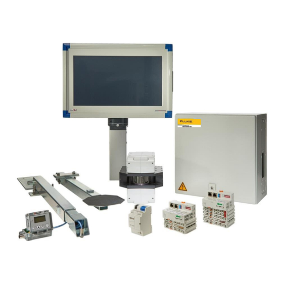
Product Description 2.1 System Overview and Arrangement of Components The TIP900 system is composed of measurement, process control, operator and graphical display HW/SW components and consists in general of the following devices: Figure 2: TIP900SYS system components, which have to be integrated... -
Page 13: Figure 4: Front View Of The Industrial Touch-Panel Pc
Industrial Terminal block, labeled for signal connection, see Figure 5 (X1, X2) Industrial 5-channel network switch (e.g. WAGO 852-111), see Figure 5 (X3) Figure 4: Front view of the Industrial Touch-Panel PC Figure 5: Rear view into the equipped Industrial Touch-Panel PC TIP900 Rev. E1 Feb 2016... -
Page 14: Figure 6: Options To Fix The Industrial Touch-Panel Pc
A compact IR sensor with 15m head cable, installed in a telescope arm A counter telescope arm with black surface paddle for good temperature reading A connection box to adapt the compact IR sensor to the Ethernet network TIP900 Rev. E1 Feb 2016... -
Page 15: Figure 8: Temperature Compensation Set
The SW components, preinstalled on the Industrial Touch-Panel PC, are: Windows 7, 64-Bit, English TIP900 process SW for wallboard image scan, defect detection and long term image archiving Wago I/O Check SW for the standard Wago 750 field bus coupler integration ... -
Page 16: Technical Data
IEC 60068-2-27, 3 axes, operating: 5 g at 11 ms, 15 g at 6 ms Dimensions 200 x 180 x 190 mm (7.8 x 7.02 x 7.41 in) Weight (incl. air purge) 7 kg (15.4 lbs) TIP900 Rev. E1 Feb 2016... -
Page 17: Figure 10: Thermal Imager Mounting Locations And Dimensions
outer 6 mm (.24 in) inner 4 mm (.16 in) Water connections outer 6 mm (.24 in) inner 4 mm (.16 in) Figure 11: Thermal Imager air purge and water cooling connections TIP900 Rev. E1 Feb 2016... -
Page 18: Tip900Sys (Telescope Arms For Temperature Compensation Set)
Technical Data 3.1.2 TIP900SYS (Telescope Arms for Temperature Compensation Set) Figure 12: Sensor Telescope Arm for Temperature Compensation Set Figure 13: Counter Paddle Telescope Arm for Temperature Compensation Set TIP900 Rev. E1 Feb 2016... -
Page 19: Tip900Sys (Ir Temperature Sensor, Mounted Close To Kiln Discharge)
50 g, 11 ms, operating, 3 axes / IEC 60068-2-27 Weight 5 50 g (1.8 oz) Material Head Stainless steel Material Head Cable PUR (Polyurethane), Halogen free, Silicone free Figure 14: Dimensions of LTS10 Sensing Head Figure 15: Spot Size Charts TIP900 Rev. E1 Feb 2016... -
Page 20: Tip900Sys (Ir Temperature Sensor Connection Box To Network)
11 to 200 Hz, 3 g above 25 Hz operating, 3 axes / IEC 60068- Shock 50 g, 11 ms, operating, 3 axes / IEC 60068-2-27 Weight 370 g (13 oz) Material die-cast zinc enclosure TIP900 Rev. E1 Feb 2016... -
Page 21: Figure 16: Dimensions Of Raymi3Comme Box
(RS485, Profibus etc.). Boxes without fieldbus have a plugged expansion feed-through port instead (M12x1.5 thread). Figure 16: Dimensions of RAYMI3COMME Box Figure 17: Terminal Wiring for the RAYMI3COMME Box TIP900 Rev. E1 Feb 2016... -
Page 22: Tip900Sys (Protective Housing For Thermal Imager, Network, Power
6.5 W Environment Operating temperature -10 to 60°C (14 to 140°F) Storage temperature -40 to 85°C (-40 to 185°F) Operating humidity 5 to 95% RH Protection 4.000 VDC ESD (Ethernet), 3.000 VDC Surge (EFT for power) TIP900 Rev. E1 Feb 2016... -
Page 23: Tip900Sys (Touch-Panel Pc With Industrial Computer Components)
Gross Weight (with all components) approx. 18 kg (39.7 lb) Power Supply 100 - 240 VAC, 50/60 Hz Power Consumption max. 140 W (total for all integrated components) Figure 19: Industrial cabinet for Touch-Panel PC and integrated components TIP900 Rev. E1 Feb 2016... -
Page 24: Scope Of Delivery
Target telescope arm (black paddle) as counterpart to compact temperature sensor, to get a defined ambient or background temperature reading DVD with TIP900 SW installation image and needed Operator Manuals in PDF Printed documentation (binder) with relevant manuals TIP900... -
Page 25: Installation
Installation 4. Installation 4.1 Pre-Installation terms and conditions For a trouble-free installation of the ordered TIP900 system and associated components, several pre- installation tasks have to be performed and guaranteed: Definition and clearance of the location for the operators Industrial Touch Panel PC Free access to cable trays and power supply (110 –... -
Page 26: Figure 20: Tip900 Definitions For Wallboard, Image Orientation And Pixel Numbering
A standard installation position of the Protected Housing with the correct thermal imager orientation in the housing has to be defined, to guarantee an easy and understandable hardware installation procedure. Figure 20: TIP900 Definitions for wallboard, image orientation and pixel numbering TIP900 Rev. E1 Feb 2016... -
Page 27: Environment
For details on grounding the mounted housings and devices, please refer to the local guidelines. The housings of all TIP900 components (protective housing, Touch-Panel PC, Compact sensor box) must have the same grounding potential. Check for good electrical contact at grounding wire port. -
Page 28: Installation Of Protective Housing With Internal Thermal Imager
Up to eight (8) in parallel feeded wallboards via the conveyance belt, will be processed by the TIP900 system. The system shall deliver thermal infrared image line scans across the inner conveyance belt width. Under the limitation of a 90° scan angle, a specific installation height above passing wallboard surfaces is mandatory. -
Page 29: Figure 23: Loose Supplied Parts For Mechanical Installation Support
W = Width of inner wallboard conveyor (required scan width for 90° scan angle) 60mm (2.362”) is the stud bolt length, which elevates the internal thermal imager above the lower edge of the protective housing Figure 24: Distance between Protective Housing and wallboard surfaces TIP900 Rev. E1 Feb 2016... -
Page 30: Electrical Installation Of The Protective Housing
RJ45 LAN to the Industrial Touch-Panel PC (< 80m distance), min Cat5e If installing the TIP900 Protective Housing in a warm environment, water-cooling may be necessary. The tubes used for water may be run through the second grommet plate! TIP900 Rev. -
Page 31: Cable Entry System
Local building codes should be observed when selecting cables! Longer cable length or less wire gauge causes a certain voltage drop on the power cable. It has to be ensured, that all devices will be supplied with sufficient voltage power! Illustrations: © Murrplastik TIP900 Rev. E1 Feb 2016... -
Page 32: Installation Of The Temperature Compensation Set
Please see chapter 3.1.2 until 3.1.4 for the dimensions and mounting points of the three items. Figure 27: Upper and lower telescope arm fixtures installed after kiln exit Figure 28: Schematic of kiln and deck outfeed arrangement TIP900 Rev. E1 Feb 2016... -
Page 33: Electrical Installation Of The Temperature Compensation Set
In a dusty environment like in the gypsum wallboard production, it’s strongly recommended to install the air-purge supply to keep the sensor head and associated mirror dust-free. Bad temperature reading influences the temperature compensation capability. TIP900 Rev. E1 Feb 2016... -
Page 34: Installation Of The Drop Gate Identification And Signaling Set
Industrial 16-channel digital input module 24VDC (e.g WAGO 750-1406) Prewired Terminal block Industrial Power Supply 24V, 1.5A (e.g. WAGO 787-1002) Figure 29: Drop gate identification and signaling set Figure 30: Schematic of drop gate wiring to identification and signaling set TIP900 Rev. E1 Feb 2016... -
Page 35: Installation Of The Industrial Touch-Panel Pc
In case of the ordered mounting option for a pedestal or swiveling supporting arm, the following details are given, see Figure 6: Options to fix the Industrial Touch-Panel PC: Pedestal Height: 1127mm (44.37 in) Aluminium Tube 70 X 90 X 1000mm Figure 31: Base mounted pedestal with mounting dimensions TIP900 Rev. E1 Feb 2016... -
Page 36: Figure 32: Wall Mounted Swiveling Supporting Arm With Dimensions
Installation Swiveling Supporting Arm Height: 422mm (16.61 in) Overhang: 745mm (29.33 in) Figure 32: Wall mounted swiveling supporting arm with dimensions Overhang ----------- Figure 33: Load diagram for wall mounted swiveling supporting arm TIP900 Rev. E1 Feb 2016... -
Page 37: Figure 34: Mounting Elements For Wall Mounted Swiveling Supporting Arm With Dimensions
Installation Aluminum Tube 70 X 90 X 500mm Aluminum Tube 70 X 90 X 250mm Figure 34: Mounting elements for wall mounted swiveling supporting arm with dimensions TIP900 Rev. E1 Feb 2016... -
Page 38: Electrical Installation Of The Touch-Panel Pc
Installation 4.6.2 Electrical Installation of the Touch-Panel PC Figure 35: Wiring Terminal Block in Touch-Panel PC TIP900 Rev. E1 Feb 2016... -
Page 39: Operation
If the TIP900 Touch-Panel PC is powered, you are logged in and no program is running, you will see three icons on your PC desktop. The TIP900 Help folder and both link icons, which were created during the SW installation process. -
Page 40: Operation Of Tip900 Monitoring And Defect Identification Sw
5.2.1 General description, assigned screen areas, related elements & menus Please see the brief general TIP900 system description under Product Description on page 11. The icon in Figure 36: Created TIP900 icons during SW installation process represent the recipe based monitoring and defect identification SW for gypsum wallboard production. -
Page 41: The Program Title & Version Line And The User Mode Dependent Menu Bar Domain
Figure 39: Program is running in Supervisor mode with administration rights 5.2.1.1.1 The program title line and its information content above, the program title line indicates the program name “TIP900”, the In the screen domain current SW version number, the selected recipe name and the specific recipe type. -
Page 42: The "Product Recipe" Selector In The Menu Bar
The “General” and the “Defect Detection” parameters are shown in the red marked box and are preset by the Supervisor during the recipe creation. See all to box assigned parameters in the following description: TIP900 Rev. E1 Feb 2016... - Page 43 A new snapshot will be started when the scanner measures a temperature above “Trigger Background-Temperature” + “Trigger Start-Delta-Temperature”. Trigger-Stop-Delta-Temperature: A snapshot will be stopped when the scanner measures a temperature below “Trigger Background-Temperature” + “Trigger Stop-Delta-Temperature”. TIP900 Rev. E1 Feb 2016...
- Page 44 In dependence of the customer specific kiln (dryer), the maximum deck number can vary up to 16 decks and is limited in the SW. Please see the description of “Global Error Max Deck X” under the previous description for “Global Error Max Deck 1”. TIP900 Rev. E1 Feb 2016...
-
Page 45: The "Edit Recipe" Selector In The Menu Bar
Save Recipe: The Save Recipe button just stores the currently modified recipe. Every recipe modification and storage action will be logged by the TIP900 SW and is displayed in the General Info (Application Log) window element. TIP900... - Page 46 Load Reference/All Decks: Herewith you are able to force the TIP900 program to set for every dryer deck a reference board map in on step. All dryer decks get the same reference board map assigned.
-
Page 47: The "Configuration" Selector In The Menu Bar
SW will be terminated, the scanner snapshots will be shifted into subfolders of the Log directory. The Incoming directory will be cleared each time the TIP900 SW is restarted. Recipes directory: The default directory where recipes are located. All recipes within this directory are shown in the drop-down-control within the "Product Recipe"... - Page 48 -- Language Settings -- Language: Program language setting to the specific location, where the program is in use. It is the application language in the TIP900 application and in the LogViewer program. Changes require an application restart to take effect.
- Page 49 Enable auto temp. scaling: Enables/Disables the automatic temperature scaling feature. Possible selection is Yes/No. Temperature unit: The default temperature unit in the TIP900 application and in the LogViewer. Changes require an application restart to take effect. -- Image View Settings --...
-
Page 50: Figure 43: Inputs/Outputs & Temperature Compensation Tab Screens In Supervisor Mode
BootP in the network. The default IP address is “192.168.42.32”. MAC address: The unique MAC address of the Wago 750 Fieldbus Coupler for outputs, which should be served via BootP and addressed via the IP address above. TIP900 Rev. E1 Feb 2016... - Page 51 Assigns the output of the application watchdog. The application watchdog applies to communication errors of the scanner, the temperature compensation (Mi3) and a crash of the TIP900 application. Selection criteria are “Relay2” or “Digital Output 2”. Output Hold Time: The reset time after a watchdog triggered event (Output) releases the hold state.
-
Page 52: Figure 44: Scanner Tab Screen In Supervisor Mode
Transmissivity: The transmissivity of the scanner window (glass cover). -- Scanner: Snapshot-- Flipped X-Axis: Flip X-Axis of the scanner snapshot. Flipped Y-Axis: Flip Y-Axis of the scanner snapshot. TIP900 Rev. E1 Feb 2016... -
Page 53: The "Maintenance" Selector In The Menu Bar
4 isolated relay Outputs can bet set individually by clicking into the black field. If activated, the background color changes from black to green. The Modbus/Ethernet status changes from green to red color, if the module is not accessible. TIP900 Rev. E1 Feb 2016... -
Page 54: Figure 46: Maintenance Of Mp150 Scanner In Supervisor Mode
Alignment Laser: Herewith you are able to switch the scanner Alignment Laser on/off. If doing this, be aware that nobody stares into the laser beam. TIP900 Rev. E1 Feb 2016... -
Page 55: Figure 47: Maintenance Tab Of Temperature Compensation In Supervisor Mode
If the Temperature Compensation box, which adapts the temperature compensation sensor head via Ethernet to the TIP900 network, is not accessible, the MI3-Box Ethernet status changes from green to red background color. In status red, no valid temperature values will be measured. -
Page 56: Figure 48: Dust Filter Change Confirmation, To Keep The Configured Filter Change Interval
To guarantee a proper running TIP900 system, a defined dust filter change has to be performed after a specified time period. The dust filter change has to be applied for all TIP900 dust filters, which are installed in the Protective Housing for the scanner and the Touch Panel PC. -
Page 57: The "Show Fullscreen" Selector In The Menu Bar
The process screens display in full screen mode Board Map display in full screen mode Figure 49: Process Screens: Display of Board Map Dryer Profile display in full screen mode Figure 50: Process Screens: Display of Dryer Profile (8 decks) TIP900 Rev. E1 Feb 2016... -
Page 58: Figure 51: Process Screens: Boards Display Of 2 Boards Per Deck
Operation Boards display in full screen mode Figure 51: Process Screens: Boards Display of 2 boards per deck Temperature display in full screen mode Figure 52: Process Screens: Temperature curve for min., max., average temperature TIP900 Rev. E1 Feb 2016... -
Page 59: Figure 53: Process Screens: Comparison Current Boards To Reference Boards
Reference display in full screen mode Figure 53: Process Screens: Comparison current boards to reference boards Slice Horizontal temperature slice display in full screen mode Figure 54: Process Screens: Horizontal slice of boards temperature distribution TIP900 Rev. E1 Feb 2016... -
Page 60: Figure 55: Process Screens: Vertical Slice Of Boards Temperature Distribution
Operation Slice Vertical temperature slice display in full screen mode Figure 55: Process Screens: Vertical slice of boards temperature distribution Inspect Board Map display in full screen mode Figure 56: Process Screens: Inspect Board Map TIP900 Rev. E1 Feb 2016... -
Page 61: Figure 57: Process Screens: Deck Statistics Of Good And Bad Boards
Figure 57: Process Screens: Deck Statistics of good and bad boards Deck History display by deck and row in full screen mode Figure 58: By deck history of good/bad boards Figure 59: By row history of good/bad boards TIP900 Rev. E1 Feb 2016... -
Page 62: The "Login Supervisor" And The "Logout Supervisor" Selectors
During the very first TIP900 program installation, there is no specific supervisor password preset. It is empty and needs to be set by the supervisor in the configuration menu, see chapter 5.2.1.1.4. -
Page 63: The Board Map Display Domain
Please see under chapter 5.2.1 for detailed information regarding the boards map domain location on the PC screen of the TIP900 monitoring and defect identification SW. The board map display shows in an assigned domain the currently produced and scanned gypsum wallboards, which just passed the line scanner (thermal imager). - Page 64 0°C or 32°F assigned to. This is done by the board border recognition process in the TIP900 software. : In dependence of the board movement in direction to the scanner, it has to be marked, where board leading edge = L and the board trailing edge = T is.
-
Page 65: The Process Screens Display Domain
The displayed line for the Overall Temperature shows the calculated average temperature over 123 board sets per deck. The line for the Current Temperature shows the calculated average temperature of the currently processed board set. TIP900 Rev. E1 Feb 2016... -
Page 66: The Boards Display
Regarding the boards map display in chapter 5.2.1.2, there is just one outer frame per boards set, to identify defects on boards set level. No differentiation to a single board is possible there. TIP900 Rev. E1 Feb 2016... -
Page 67: The Temperature Display
(e.g. 8 decks). The both slider scales, one on the right hand side and the other on the lower picture side, are for the individual adaption (extension, compression) of the X/Y-axis. TIP900 Rev. E1 Feb 2016... -
Page 68: The Reference Boards Display
The Reference Boards Display shows the assigned reference boards per dryer deck, which was set by the supervisor during the “Edit Recipe” procedure. See chapter 5.2.1.1.3 for more details regarding the reference board assignment by the supervisor. TIP900 Rev. E1 Feb 2016... -
Page 69: The Horizontal Slice Through The Boards Map
The black curve displays the horizontal slice of the normalized board temperature values. That means all background temperature values will be normalized to 0°C / 32°F. A right hand side slider allows the individual display adaption (extension, compression) of the Y-axis temperature values for the horizontal slice. TIP900 Rev. E1 Feb 2016... -
Page 70: The Vertical Slice Through The Boards Map
The black curve displays the vertical slice of the normalized board temperature values. That means all background temperature values will be normalized to 0°C / 32°F by a sophisticated SW algorithm. A bottom slider allows the individual display adaption (extension, compression) of the X-axis temperature values for the vertical slice. TIP900 Rev. E1 Feb 2016... -
Page 71: The Inspect Boards Map Display
“Boards Map” display domain. Such proceeding changes automatically to the sub-display “Inspect Board Map” under the process screens domain. Now a deeper analysis of the captured board map is possible during a continuing production process. TIP900 Rev. E1 Feb 2016... -
Page 72: The Deck Statistics Display
Especially the kiln deck temperature variance has to be taken into account, if the variance between the decks is high. Please use individual reference board set per deck or adapt the individual defect detection threshold temperature per deck. TIP900 Rev. E1 Feb 2016... -
Page 73: The Hardware Status Indicator Display Domain
The push button initiates a sub-program call of the TIP900_LogViewer program. The final selected recipe name defines the database folder for the logged thermal image data, where the program relates to. TIP900 Rev. E1 Feb 2016... -
Page 74: The General Information Display Domain
An easy way to mark and assign a deck specific board map image as a good reference board map to the deck number is integrated. Please see in chapter 5.2.1.1.3 “Load Reference” for detailed information. under TIP900 Rev. E1 Feb 2016... -
Page 75: Operation In "Standard Operator" Mode
Figure 74: Program is running in Standard Operator mode with restricted rights A double click on the icon in Figure 36: Created TIP900 icons during SW installation process starts the program in the standard operator mode with restricted rights. In such mode is just a reduced main menu with five (5) selection items available. -
Page 76: Operation In "Supervisor" Mode
As a safety feature is an automatic logout from supervisor mode integrated, which takes place after about 5 minutes without supervisor interaction. This should avoid leaving all supervisor priorities to the standard operator staff in case of missing a correct logout as supervisor. TIP900 Rev. E1 Feb 2016... -
Page 77: Operation Of Tip900_Logviewer Online/Offline Viewing Sw
SW of archived thermal images in gypsum wallboard production. A double click on the icon starts the program. Another activation method of the program is out of the running “TIP900 monitoring and defect identification SW” program by pressing the push button This initiates a sub-program call of the TIP900_LogViewer program with the final selected recipe name as passed parameter. -
Page 78: The Program Title & Version Line With The Menu Bar Domain
Logfile name will be displayed. After a selection of a Logfile and the confirmation to open the file, the filename will be displayed. A program start by a simple click onto the LV-push button in the “TIP900 monitoring and defect identification SW” application, displays the last chosen Logfile name, as shown above. -
Page 79: The File Selector In The Menu Bar
Operation 5.3.1.1.2 The File selector in the menu bar Figure 78: TIP900 – Log Viewer File selector in the menu bar No Logfile name was passed during program or sub-program call, which is why no Logfile is opened and all sub-screens are empty. -
Page 80: Figure 80: Tip900 - Log Viewer With Selected And Opened Logfile
Figure 81: TIP900 – Log Viewer to open a Logfile by Date filtering Select the known Logfile archive date and confirm in the subsequent window to open the individual marked file. -
Page 81: Figure 82: Tip900 - Log Viewer To Reload An Opened Logfile
Operation Figure 82: TIP900 – Log Viewer to reload an opened Logfile The already opened Logfile is reloaded in case the logging process is still running and new board maps are archived during the inspection procedure. You’ve got also the choice to reload the opened Logfile by pressing the function key F5. -
Page 82: Figure 84: Tip900 - Log Viewer With Selected And Opened Logfile
Figure 85: TIP900 – Log Viewer to open a Logfile by Date filtering Select the known Logfile archive date and confirm in the subsequent window to open the individual marked file. -
Page 83: Figure 86: Tip900 - Log Viewer To Reload An Opened Logfile
Operation Figure 86: TIP900 – Log Viewer to reload an opened Logfile The already opened Logfile is reloaded in case the logging process is still running and new board maps are archived during the inspection procedure. The latest archived board maps are added to the last opened Logfile display table. -
Page 84: Figure 88: Tip900 - Log Viewer To Export A Board Map In Binary Format
*.PNG file format. Select the folder of your choice in the subsequent window and confirm to save the binary file. Figure 89: TIP900 – Log Viewer to save the selected board map in binary format The save button confirms your selection and stores the board map binary file to a destination folder of your choice. -
Page 85: Figure 90: Tip900 - Log Viewer To Export A Reference Board Map In Binary Format
*.bin, *.JPG and *.PNG file format. Select the folder of your choice in the subsequent window and confirm to save the binary file. Figure 91: TIP900 – Log Viewer to save the selected reference board map in binary format The save button confirms your selection and stores the reference board map binary file to a destination folder of your choice. -
Page 86: Figure 92: Tip900 - Log Viewer To Export The Board Map Data Table In Csv Format
Operation Figure 92: TIP900 – Log Viewer to export the board map data table in CSV format The data table of the opened Logfile will be exported as a CSV (comma separated value) formatted file to a destination folder of your own choice. A CSV file export is generally used for further processing, analysis or statistical evaluations under spreadsheet programs like EXCEL. -
Page 87: The Color Table Selector In The Menu Bar
Operation Figure 94: TIP900 – Log Viewer to exit/terminate the program The exit field selection terminates the program execution and returns to the invoked user interface. 5.3.1.1.3 The Color Table selector in the menu bar Figure 95: TIP900 – Log Viewer Color Table selections Herewith the color to temperature assignment can be adapted for the image viewing of the archived board map data. -
Page 88: The Map Data Selector In The Menu Bar
(black area around the boards), whereas the minimum temperature is close to the lowest acquired value (e.g. floor ambient temperature). Figure 97: TIP900 – Log Viewer display of Boards Only Map Data The selection of “Boards Only” map data calculates and displays the maximum, the average and minimum temperature values per scanned board map set, whereas “Boards Only”... -
Page 89: The Settings Selector In The Menu Bar
5.3.1.1.7 The About selector in the menu bar Figure 100: TIP900 – Log Viewer display About the integrated help function and SW information The TIP900 – LogViewer SW help function allows to search for several specific topics. -
Page 90: The Tip900-Logviewer Binary Archive File Table Domain
5.3.1.3 The TIP900-LogViewer board map inspector domain Figure 102: TIP900 – Log Viewer board map inspection of a reference board map Figure 103: TIP900 – Log Viewer board map inspection of a scanned board map TIP900 Rev. -
Page 91: The Tip900-Logviewer Dryer Deck Specific Reference Board Map Display Domain
1:1 standard size, image or horizontal slice view, gray level or color view. 5.3.1.4 The TIP900-LogViewer dryer deck specific reference board map display domain Figure 104: TIP900 – Log Viewer reference board map display domain The dryer deck specific reference board map display domain is for finding and inspecting abnormalities of assigned reference board maps. -
Page 92: The Tip900-Logviewer Dryer Deck Related Archived Board Map Display Domain
5.3.1.6 The TIP900-LogViewer historical board map temperature display domain Figure 106: TIP900 – Log Viewer of “Full Map Data” & “Boards Only Map Data” The historical board map temperature display domain shows the minimum, average and maximum temperature of each scanned deck specific board set. -
Page 93: Configuration
Make sure that a possible firewall does not block needed communication ports The following sections of this manual describe the HW and SW configuration of the TIP900 system. A complete configuration requires the following steps: 1. Installation of the system software. -
Page 94: Options
Pay particular attention to the safety instructions regarding wall/rack mounted devices with overhang. Determine the right mounting loads and consider Figure 33: Load diagram for wall mounted swiveling supporting arm, to avoid device damage and personal injury. TIP900 Rev. E1 Feb 2016... -
Page 95: Accessories
Touch-Panel PC mounting method. Please refer to Figure 6: Options to fix the Industrial Touch-Panel PC and chapter 4.6.1 for detailed installation dimensions. 8.3 TIP900-HSFIC4 (High Speed Fiber Optic / RJ45 Converter Set) The high-speed fiber optic to LAN/RJ45 converter set consists of two (2) converters, a 2m long standard Cat5e LAN/Ethernet cable and a 2m long fiber optic cable with SC-type connectors. -
Page 96: Appendix
Restart the Touch-Panel PC and login as an administrator with full permissions Insert the TIP900 SW-DVD or a storage medium with the installation program on it. Double click on the <Setup.exe> file. The install setup application will start, showing the following screens in a sequential order. - Page 97 Appendix Confirm the first install screen with the warning hint by clicking on Next >! Click on the Check-Button “I Agree” and confirm the license agreement text by clicking on Next >! TIP900 Rev. E1 Feb 2016...
- Page 98 Appendix Decide, if “Everyone” or “Just me” should be able to use the installed TIP900 software by clicking the Check-Button of your choice. It’s recommended to leave the suggested folder name unchanged, to ease remote trouble reporting and offsite support. Confirm your selection by clicking on Next >! Confirm the TIP900 software installation process by clicking on Next >!
- Page 99 Information screen shows, that the TIP900 software is being installed. This could take some seconds. User Account Control screen asks to permit the installation of the TIP900 software with all changes on the computer. Please confirm and permit by clicking on the “Yes” Button.
- Page 100 Appendix Read the final installation indication and close the installation by clicking on the “Close” Button. TIP900 Rev. E1 Feb 2016...