Table of Contents
Advertisement
Quick Links
Advertisement
Table of Contents

Related Manuals for EAW QX Series


Summary of Contents for EAW QX Series
- Page 1 Passive Point Source Application Guide...
-
Page 2: Table Of Contents
Using EAW Resolution™ Passive Point Source Products - MKC Series Passive Point Source Products - MKi Series Passive Point Source Products - MKD Series Passive Point Source Products - QX Series Pairing with EAW Power Amplifiers Input Connections Using UXA4410 Power Amplifier... -
Page 3: Using The Loudspeaker
Resolution Users will need to perform the following 2 help file. general tasks to properly put a EAW passive point source product into use. This manual Using EAW Resolution™ includes details for each task. EAW Resolution is the key to determining 1. -
Page 4: Passive Point Source Products - Mkc Series
►Available WP Models for long term outdoor installations. ►Multitap transformer options provide solutions for distributed and fill systems. ►MKC Series can be deployed in either vertical or horizontal orientations. MKC60 - No grill Tel 800 992 5013 / +1 508 234 6158 www.eaw.com... -
Page 5: Passive Point Source Products - Mki Series
► 120° x 60° ► User rotatable horns let contractors 90° mount the enclosures vertically or 45° horizontally and still keep the desired coverage pattern. INSIDE EAW TECHNOLOGIES Common dimensions between MK2300 and MK5300 series Coverage 90° options with specific 45°... -
Page 6: Passive Point Source Products - Mkd Series
HP woofers for maximum performance Large format rotatable horn for Compact extended pattern shape with control curved MKD1000 - No Grill front for concealed install Tel 800 992 5013 / +1 508 234 6158 www.eaw.com... -
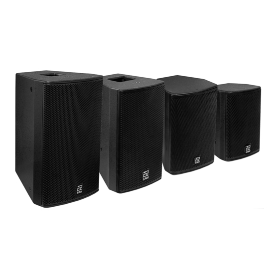
Page 7: Passive Point Source Products - Qx Series
Passive Point Source Application Guide Passive Point Source Products - QX Series QX544i QX594i 45° x 45° 90° x 45° ► ► QX564i QX596i ► 60° x 45° ► 90° x 60° QX566i 60° x 60° ► QX326 QX394 ►... - Page 8 For instance, if QX series is specified but cost is Below are some examples on how directivity of concern, MKD series is a viable solution with scales between each product line (1 octave, only a small sacrifice in performance.
-
Page 9: Pairing With Eaw Power Amplifiers
Passive Point Source Application Guide MKC120 Pairing with EAW Power Amplifiers Below are the recommended configurations when using UXA amps with point source products Tel 800 992 5013 / +1 508 234 6158 www.eaw.com... - Page 10 Passive Point Source Application Guide UXA4410 Front & Back Panel UXA4401 UXA4403 Tel 800 992 5013 / +1 508 234 6158 www.eaw.com...
-
Page 11: Input Connections
Input Connections - Neutrik NL4, 2-pin barrier strip INPUT SIGNAL 2-Way, Single-Amp (LF/HF) MKC50 & MKC60 INPUT SIGNAL 2-Way, Single-Amp (LF/HF) MK8100i*, MKD800*, MKC80 & MKC120 *Labeling may vary with these products Tel 800 992 5013 / +1 508 234 6158 www.eaw.com... - Page 12 Low Frequency / Mid Frequency / High Frequency User Supplied Power Amplifier –or– Integral Amplifier Passive LPFs, HPFs, and EQ integral to the loudspeaker EAW Focusing Digital Signal Processor capable of implementing EAW Tel 800 992 5013 / +1 508 234 6158 www.eaw.com...
- Page 13 Low Frequency / Mid Frequency / High Frequency User Supplied Power Amplifier –or– Integral Amplifier Passive LPFs, HPFs, and EQ integral to the loudspeaker EAW Focusing Digital Signal Processor capable of implementing EAW Tel 800 992 5013 / +1 508 234 6158 www.eaw.com...
- Page 14 Low Frequency / Mid Frequency / High Frequency User Supplied Power Amplifier –or– Integral Amplifier Passive LPFs, HPFs, and EQ integral to the loudspeaker EAW Focusing Digital Signal Processor capable of implementing EAW Tel 800 992 5013 / +1 508 234 6158 www.eaw.com...
-
Page 15: Using Uxa4410 Power Amplifier
2. Power Switch– Applies mains power to the device. If the device has entered Sleep mode, it may be woken up again either from the EAW Resolution software application, or by switching this switch off, then on again. 3. Menu Buttons– There are three buttons to determine which section of the device to view or edit. -
Page 16: Uxa4410 Amplifier Output Connections
9. Mute Buttons– DSP output mute status is indicated and controlled by an illuminated button for each channel. These flash when the entire unit is muted from the AUXA port or from EAW Resolution software Mute-All, or if this channel has been muted by the protection systems. - Page 17 More than one speaker can be connected to each channel provided the total impedance per channel is not less than 2 ohms. In bridged mode the minimum total impedance should not be less than 4 ohms. Tel 800 992 5013 / +1 508 234 6158 www.eaw.com...
-
Page 18: Uxa4410 Load Matching
DANTE networks with 2 or less multicast flows. Also important, is though these products may receive DANTE input signal, they do not support DANTE output (i.e. cannot be used as an on- ramp). When first opening Resolution, start by switching to Network Configuration View. Tel 800 992 5013 / +1 508 234 6158 www.eaw.com... - Page 19 To add a processor or amplifier to the system, click on the “+” symbol next to Processors & Amplifiers in the Project Explorer window. Upon being prompted, choose a name and a product from the devices available. Click “OK” once complete. Tel 800 992 5013 / +1 508 234 6158 www.eaw.com...
- Page 20 The selected device will now be loaded into the system. In this case, as offline. To connect the processor or amplifier to the system, start by clicking Network > Connect. Tel 800 992 5013 / +1 508 234 6158 www.eaw.com...
- Page 21 A prompt may appear if Resolution is not in sync with the device. Choose whether to push the Resolution settings to the device, or cancel to use the last known settings. Tel 800 992 5013 / +1 508 234 6158 www.eaw.com...
- Page 22 Resolution settings to the device, or cancel to use the last known settings. At this point, the device is online and ready to use in the system (as indicated by the green light). Tel 800 992 5013 / +1 508 234 6158 www.eaw.com...
-
Page 23: Uxa4410 Input Section
3. Signal Routing: Assign input sources to input channels, or combine input sources to a single input channel. Select an input source type between Analog, AES3, and Dante (See both pull- down menus below). Tel 800 992 5013 / +1 508 234 6158 www.eaw.com... -
Page 24: Uxa4410 Output Section
2. EQ/Filters Section: Manually adjust settings for all EQ/Filter bands. Use << >> buttons to navigate from one band to the next. There is an additional pull-down menu to choose type of filter. Once a Greybox is loaded, only the HPF may be modified. Tel 800 992 5013 / +1 508 234 6158 www.eaw.com... -
Page 25: Loading Greyboxes (Eaw Speaker Preset Files) Into Uxa4410
Passive Point Source Application Guide 3. Greybox: Load EAW Greyboxes and set Input source (See pull down menu below). 4. Output Section: Adjust gain, invert polarity, and set delay or delay distance. Unity Gain and Invert Polarity is disabled once a Greybox is loaded. - Page 26 Passive Point Source Application Guide Click any output channel, then click on Select/Configure Greybox. On the main Greybox Configuration window, click Add Greybox… Tel 800 992 5013 / +1 508 234 6158 www.eaw.com...
- Page 27 Leg, Amp Type, Amp Gain, and Listener Distance. Either choose an available Amp Type or create one new by clicking on <New…> under the pull- down menu. Tel 800 992 5013 / +1 508 234 6158 www.eaw.com...
- Page 28 Entry Method may either be by Voltage or Power. Back to the Greybox configuration window, the newly created amplifier will now be available on all channels under Amp Type. Click “OK” once complete. Tel 800 992 5013 / +1 508 234 6158 www.eaw.com...
-
Page 29: Unify Processor Interfaces For Uxa4410 Amplifiers
Dante card when Resolution is connected to the Ethernet port of a UX processor or UXA amplifier. The IP address of the Dante card is stored in the internal memory. This is only required once unless the internal Dante card is replaced. Tel 800 992 5013 / +1 508 234 6158 www.eaw.com... - Page 30 NOTE: Processor or Amplifier control will work fine without a unified Dante port. With the Unify Processors window open, select the processor and Dante interface that needs to connect. Click Unify to complete. Tel 800 992 5013 / +1 508 234 6158 www.eaw.com...
- Page 31 After the function is complete, the linked interface may be viewed in the bottom pane as illustrated below. Click Done to accept or Break to undo and reverse the action. Under Online Devices, Resolution now associates the Dante card with the processor or amplifier. Tel 800 992 5013 / +1 508 234 6158 www.eaw.com...
-
Page 32: Using Uxa4401 & Uxa4403 Power Amplifiers
Diagram 1c illustrates the use of connecting plates. Connection Plate + 4 x M3 x 6 countersunk Diagram 1c 2 x UXA4401with Connection Plate. 2 positions Tel 800 992 5013 / +1 508 234 6158 www.eaw.com... - Page 33 25mm along at least one side Mounting Plate + should be retained at all times. 2 x M3 x 6 countersunk Diagram 2b UXA4401 wall and under-desk mount. Tel 800 992 5013 / +1 508 234 6158 www.eaw.com...
-
Page 34: Installation Of Uxa4403
This is illustrated in Diagram 3a. Diagram 3a UXA4403 amplifier dimensions. (Shaded area defines ventilation space.) 440 mm 17.3 in 332 mm 13.1 in 88 mm 3.5 in Tel 800 992 5013 / +1 508 234 6158 www.eaw.com... -
Page 35: Configuring Uxa4401 & Uxa Amplifier
Access Point WiFi password is changed following initial amplifier has network connectivity. wireless connection. 3. The UXA Amplifier amplifier default LAN IP address 192.168.64.100. Configure the laptop or desktop computer for a fixed IP address in the Tel 800 992 5013 / +1 508 234 6158 www.eaw.com... - Page 36 Diagram 4a Configuration Dashboard display Note: When adjusting input gain, the input level display should remain green. If it displays red, the input gain Diagram 4b Input Tab display should be reduced. Tel 800 992 5013 / +1 508 234 6158 www.eaw.com...
- Page 37 The overall zone volume may need to be increased Diagram 4c Zone Tab display Diagram 4e Zone Tab display Tel 800 992 5013 / +1 508 234 6158 www.eaw.com...
- Page 38 • The Equalizer menu (Diagram 4h) enables subwoofer. parametric equalization to be applied to individual amplifier outputs. Equalizer settings configured for one amplifier output. Diagram 4f Diagram 4h Tel 800 992 5013 / +1 508 234 6158 www.eaw.com...
- Page 39 Note: FIR coefficient files in either .csv or .txt format can be imported. • The Driver Alignment preset menu enables delay to be applied to individual amplifier outputs. Diagram 4i Speaker Preset Parameters Tel 800 992 5013 / +1 508 234 6158 www.eaw.com...
- Page 40 FIR in the preset menu provides a way to load a • file with determined FIR filters and parameters (Diagram 4n). Diagram 4n Preset FIR Diagram 4l Preset Crossover & Gain Tel 800 992 5013 / +1 508 234 6158 www.eaw.com...
- Page 41 (Diagram 4q). Note: In automatic mode, the peak limiter parameters adjust automatically in response to Crossover & Gain high-pass filter settings. Diagram 4r Preset Limiter Tel 800 992 5013 / +1 508 234 6158 www.eaw.com...
- Page 42 Creat new library • The WiFi menu enables configuration and reset of Rename library Edit or delete library the wireless network options and parameters. Diagram 4t Speaker Library Creation and Management Tel 800 992 5013 / +1 508 234 6158 www.eaw.com...
- Page 43 The following paragraphs describe and illustrate the recommended procedure for configuring input, zone and output routing. A general signal flow schematic is also illustrated in Diagram 4u. Diagram 4u Signal Flow Schematic (four output amplifier) Tel 800 992 5013 / +1 508 234 6158 www.eaw.com...
- Page 44 • Specify an input for the zone by selecting from the drop-down menu. Selecting a stereo input for a mono zone will automatically sum the stereo channels to mono. Tel 800 992 5013 / +1 508 234 6158 www.eaw.com...
- Page 45 Standby or Mute depending on options selected in the GPIO Settings Menu Diagram 4w Potentiometer connections for re- mote volume control via GPIO. Note: Diagram 6c illustrates use of the GPIO connector. Tel 800 992 5013 / +1 508 234 6158 www.eaw.com...
- Page 46 Outputs 3 and 4. with the balanced inputs. Output mode options (Lo-Z or Hi-Z) can be Digital Inputs configured via the amplifier network interface. UXA amplifiers S/PDIF stereo digital audio input Tel 800 992 5013 / +1 508 234 6158 www.eaw.com...
-
Page 47: Rigging: Mounting/Suspension
Rigging Hardware and Accessories Rigging EAW loudspeakers will invariably require hardware not supplied by EAW. Various types of load-rated hardware are available from a variety of third-party sources. There are a number of companies specializing in manufacturing hardware for, designing, and installing rigging systems. -
Page 48: U-Brackets For Qx Series
Passive Point Source Application Guide U-Brackets for QX Series QX500 & QX300 Series have optional U-Brackets that may be used. These brackets my only be deployed horizontally, and MUST be used with adapter brackets that are not included with the U-Bracket kit. Without the adapter brackets, the U-brackets cannot physically attach to the cabinets. - Page 49 NOTE: Under NO circumstances is possible to suspend another loudspeaker under a QX when using available mounting points. Doing so risks both damage to the speaker and imposes a serious safety risk. The supported weight is for one QX series product only. Weather Protection for QX Series WP versions of all QX models are available.
-
Page 50: U-Brackets For Mkd Series
It is important to note the two center holes and two outer holes on U-Bracket (as indicated below) is meant for cable pass through and NOT for mounting (unless for a bolted structural "ceiling mount" suspension) Tel 800 992 5013 / +1 508 234 6158 www.eaw.com... - Page 51 NOTE: Under NO circumstances is possible to suspend another loudspeaker under a MKD when using available mounting points. Doing so risks both damage to the speaker and imposes a serious safety risk. The supported weight is for one MKD series product only. Tel 800 992 5013 / +1 508 234 6158 www.eaw.com...
-
Page 52: Splay Brackets (Mkd1000 Series Only)
Application Guide Splay Brackets (MKD1000 Series only) Required Tools & Supplies • 6mm Allen Wrench Inventory your kit Part # Part Name Quantity Reference Suspension Rigging Bracket Cabinet Rigging Bracket Tel 800 992 5013 / +1 508 234 6158 www.eaw.com... - Page 53 Figure 1 - Remove screws from MKD1000 cabinets 3. Line up holes on bottom speaker to rear cabinet rigging points, then select and secure the angle suggested from Resolution 2 using supplied hardware screws (See Figure 2) Tel 800 992 5013 / +1 508 234 6158 www.eaw.com...
- Page 54 Passive Point Source Application Guide Select Angle Figure 2 (above) & Figure 3 (below) - Secure to bottom MKD Cabinet and select angles Tel 800 992 5013 / +1 508 234 6158 www.eaw.com...
- Page 55 6. Using pick point designated by Resolution 2, attach shackle to two points. This may either be two points on the Suspension Bracket (Figure 5), or two points on the Cabinet Bracket (more information on Cabinet Bracket configuration later in this document) Tel 800 992 5013 / +1 508 234 6158 www.eaw.com...
- Page 56 Follow steps 1-3 as listed above for bottom MKD1000. • For top MKD1000, Do not connect Suspension Bracket, but secure rear and splay angle using holes in the Cabinet Bracket Tel 800 992 5013 / +1 508 234 6158 www.eaw.com...
- Page 57 Passive Point Source Application Guide Figure 6 - Secure bottom and top MKD1000 with Cabinet Bracket 8. To deploy, connect shackles to rear rigging points on Cabinet Bracket and suspend. Tel 800 992 5013 / +1 508 234 6158 www.eaw.com...
-
Page 58: U-Brackets For Mk Series
MK8100, MK2300i, & MK5300i Series products all have optional U-Brackets that may be used. These brackets my only be deployed horizontally. If one of these loudspeakers is to be deployed in a vertical orientation, a different method must be used. MK2300i/MK5300i U-Bracket Instructions Tel 800 992 5013 / +1 508 234 6158 www.eaw.com... - Page 59 Passive Point Source Application Guide Tel 800 992 5013 / +1 508 234 6158 www.eaw.com...
- Page 60 Passive Point Source Application Guide MK8100 U-Bracket Instructions Tel 800 992 5013 / +1 508 234 6158 www.eaw.com...
- Page 61 NOTE: Under NO circumstances is possible to suspend another loudspeaker under a MKD when using available mounting points. Doing so risks both damage to the speaker and imposes a serious safety risk. The supported weight is for one MKD series product only. Tel 800 992 5013 / +1 508 234 6158 www.eaw.com...
-
Page 62: Plastic Pan & Tilt Bracket For Mkc50/60
Plastic Pan & Tilt Bracket for MKC50/60 1. Inventory your kit Item Description Quantity EAW MKC Plastic Wall Mount Speaker Bracket EAW MKC Plastic Wall Mount Wall Bracket EAW MKC Plastic Wall Mount Link Bracket NUT LOCK M6 SCREW SS Alloy Steel M6 x 1.00 x 25mm Long Flanged... - Page 63 Any geometric or structural modifications to the MKC Series Pan & Tilt Bracket or hardware are not EAW-approved will void the warranty and may result in damage, injury, or death. e. WARNING: Take care when lifting MKC Series products to avoid harm or damage to product.
- Page 64 To connect bracket to the speaker, mounting hole on MKC50 or MKC60 remove hardware from rear of MKC50 or MKC60, place speaker bracket over mounting pattern, and secure with previously removed hardware. Tel 800 992 5013 / +1 508 234 6158 www.eaw.com...
- Page 65 Once desired angle is achieved, fully tighten the screw. Connecting the Pan & Tilt Wall and vi. Repeat the last two steps above to achieve Speaker Brackets using the Link Bracket second pan or tilt angle. Tel 800 992 5013 / +1 508 234 6158 www.eaw.com...
- Page 66 Speaker Bracket or Link Bracket. Carefully lower the loudspeaker to the ground. b. Remove the mounting hardware securing the Wall Bracket to the mounting surface. c. Discard all damaged components. Tel 800 992 5013 / +1 508 234 6158 www.eaw.com...
-
Page 67: Metal Pan & Tilt Bracket For All Mkc Models
Metal Pan & Tilt Bracket for all MKC Models 1. Inventory your kit Item Description Quantity EAW MKC Metal Wall Mount Speaker Bracket EAW MKC Metal Wall Mount Wall Bracket Button Head Hex Drive Screw 18-8 Stainless Steel Split Lock Washer... - Page 68 Any geometric or structural modifications to the MKC Metal Series Pan & Tilt Bracket or hardware are not EAW-approved will void the warranty and may result in damage, injury, or death. d. WARNING: Take care when lifting larger MKC Series products to avoid harm or damage to product.
- Page 69 To connect bracket to the or MKD526 speaker, remove hardware from rear of MKC Series or MKD526, place speaker bracket (B) over mounting pattern, and secure with previously removed hardware. Tel 800 992 5013 / +1 508 234 6158 www.eaw.com...
- Page 70 Loosen Button Head Hex Drive Screw (C) 10°,25° 10°,25° connecting wall and cabinet bracket using a 20°,15°,30° 20°,15°,30° 5°,20° 5°,20° 6mm allen wrench iv. Once desired pan or tilt angle is achieved, fully tighten the bolt. Tel 800 992 5013 / +1 508 234 6158 www.eaw.com...
- Page 71 Inspect hardware mounting the MKC Series loudspeaker to the brackets for corrosion or looseness. Tighten loose hardware. Replace and discard corroded hardware. g. Clean the MKC Series Metal Pan and Tilt Brackets and MKC Series or MKD526 Loudspeaker with a dry cloth. Tel 800 992 5013 / +1 508 234 6158 www.eaw.com...
-
Page 72: U-Brackets For Mkc Series & Mkd526
Inventory your kit Item Description Quantity Bracket Button Head Screw Flat Washer Split-lock Washer Rubber Washer Socket Head Screw Flat Washer Split-lock Washer **Tools Needed: 3mm & 6mm Allen wrench** Tel 800 992 5013 / +1 508 234 6158 www.eaw.com... - Page 73 Each bracket are designed to suspend only one loudspeaker per bracket. d. Any geometric or structural modifications to the bracket or hardware that is not EAW- approved will void the warranty and may result in damage, injury, or death.
- Page 74 1 or 2 orientation and before installing an MKC Series or MKD526 loudspeaker to the bracket. Any geometric or structural modifications to the brackets or hardware that are not EAW-approved will void the warranty and may result in damage, injury, or death.
- Page 75 Onto each of two button head screws (B), place a split-lock washer (C) and a flat washer (D). • Onto each of the socket head screw (F), place a split-lock washer (H) and a flat washer (G). Tel 800 992 5013 / +1 508 234 6158 www.eaw.com...
- Page 76 Confirm the loudspeaker is level or plumb depending on the configuration. b. Confirm the aim angle is as expected. c. Confirm all hardware is tight. d. For weather protected applications, confirm all sealants were applied properly. Tel 800 992 5013 / +1 508 234 6158 www.eaw.com...
- Page 77 Carefully lower the bracket to the ground. c. Discard all damaged components. EU Declaration of Conformity EAW North America Inc hereby declares that this device is in compliance with Directive 2006/42/EC A copy of this EU Declaration of Conformity is available at https://eaw.com/downloads/#142-...
- Page 78 Passive Point Source Application Guide APPENDIX A - MKD526 Bracketry U-Bracket Under Balcony Bracket (WP not Yoke Bracket available) Tel 800 992 5013 / +1 508 234 6158 www.eaw.com...
- Page 79 Passive Point Source Application Guide APPENDIX B - MKC Series Bracketry WP Brackets ONLY MKC50 MKC60 MKC80 MKC120 Tel 800 992 5013 / +1 508 234 6158 www.eaw.com...
-
Page 80: Mkc Series Small Ceiling Bracket
Passive Point Source Application Guide MKC Series Small Ceiling Bracket Inventory your kit **Tools Needed: 3mm & 6mm Allen wrench** Tel 800 992 5013 / +1 508 234 6158 www.eaw.com... - Page 81 Any geometric or structural modifications to the MKC Series Pan & Tilt Bracket or hardware are not EAW-approved will void the warranty and may result in damage, injury, or death. d. MKC Series Pan & Tilt Bracket is not intended to be used with direct exposure to elements, and is not approved in situations where weather protection is required.
- Page 82 Consider orientation of loudspeaker (horizontal or vertical) before securing speaker bracket. Ceiling Bracket Only iii. To connect bracket to the speaker, remove hardware from rear of MKC50 or MKC60, place speaker bracket over Tel 800 992 5013 / +1 508 234 6158 www.eaw.com...
- Page 83 Rotate or tilt MKC loudspeaker using the moulded grooves to lock angle in place. iv. Once desired angle is achieved, fully tighten the screw. Connecting the Pan & Tilt Wall and Speaker Brackets Tel 800 992 5013 / +1 508 234 6158 www.eaw.com...
- Page 84 Repeat the last two steps above to achieve Speaker Brackets using the Link Bracket second pan or tilt angle. Plastic Pan & Tilt Bracket Assembly Mounted to Ceiling Bracket Tel 800 992 5013 / +1 508 234 6158 www.eaw.com...
- Page 85 Speaker Bracket or Link Bracket. Carefully lower the loudspeaker to the ground. b. Remove the mounting hardware securing the Wall Bracket to the mounting surface. c. Discard all damaged components. Tel 800 992 5013 / +1 508 234 6158 www.eaw.com...
-
Page 86: Mkc Series Large Ceiling Bracket
Passive Point Source Application Guide MKC Series Large Ceiling Bracket Inventory your kit **Tools Needed: (2)13mm wrench, 2.5mm & 6mm Allen wrench** Tel 800 992 5013 / +1 508 234 6158 www.eaw.com... - Page 87 Any geometric or structural modifications to the MKC Large Ceiling Bracket or hardware are not EAW-approved will void the warranty and may result in damage, injury, or death. d. WARNING: Take care when lifting larger MKC Series products to avoid harm or damage to product.
- Page 88 To connect bracket to the speaker, remove hardware from rear of MKC Ceiling Bracket Only loudspeaker, place speaker bracket over mounting pattern, and secure with previously removed hardware. Tel 800 992 5013 / +1 508 234 6158 www.eaw.com...
- Page 89 NOTE: Not all angles will be achievable due to the physical restraints of loudspeakers used with bracket. NOTE: Depending on orientation of the wall bracket pan and tilt hardware configuration will vary Tel 800 992 5013 / +1 508 234 6158 www.eaw.com...
- Page 90 Inspect hardware mounting the MKC Series loudspeaker to the brackets for corrosion or looseness. Tighten loose hardware. Replace and discard corroded hardware. g. Clean the MKC Series Brackets and MKC Series loudspeakers with a dry cloth. Tel 800 992 5013 / +1 508 234 6158 www.eaw.com...
- Page 91 Passive Point Source Warranty Application Guide These EAW products were designed and engineered at our headquarters in Whitinsville, MA USA and go through multiple quality checks during manufacturing. We guarantee our loudspeakers against defects in workmanship, materials and against malfunctions for a period of 6 years from date of delivery.