
Related Manuals for BAFANG MM G333.250.C


Summary of Contents for BAFANG MM G333.250.C
-
Page 1: Table Of Contents
6 DEALER MANUAL FOR M410 (MM G333.250.C) CONTENT 6.1 Introduction 6.3.3 Cabling 6.2 Specifications 6.3.4 Cable connector and method of using BAFANG tool 6.2.1 Outline and geometric size 6.3.5 Bash Guard and Cover Installation 6.3.6 Chain Wheel Installation 6.2.2 Surface 6.3.7 Crank Installation 6.2.3 Storage Information... -
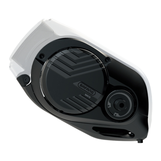
Page 2: Introduction
• Identification There are the unique identification of the product on the housing, as shown in figure: • Product Model MM G333.250.C Note: Contents in Label part are important • Scope of Application information of this product. Please keep them... -
Page 3: Specifications
6.2 SPECIFICATIONS ① Motor model: MM G333.250.C Rated power (W) Rated voltage (V) 36 / 43 / 48 Waterproof IP65 Certification CE / ROHS / EN14766 Outdoor Temperatures -20℃~45℃ 6.2.1 Outline and geometric size BF-DM-C-MM G333-EN November 2019... -
Page 4: Surface
Chain line(CL): 53.5 mm Shaft standard: BAFANG 6.2.2 Surface Shockproof black coating 6.2.3 Storage Information The pedelec should be stored in a ventilated humid and dry room. Avoid storing the pedelec near strong magnetic objects. BF-DM-C-MM G333-EN November 2019... -
Page 5: Drive Unit Installation
To fasten screws on the motor cover and cable cover T10 Torx screw driver To lock and loosen the lock nuts on the chain wheel BAFANG tool Socket spanner (BAFANG: diameter=17.7mm, To fasten nuts onto the frame interface and the drive... -
Page 6: Install Drive Unit To Connection Interface
6.3.2 Install Drive Unit to Connection Interface M8 bolt M8 flat washer M8 lock nut Tool-socket spanner Steps: 1) Align the Hole 1 on the frame interface with the mounting hole on the motor. 2) Rotate the motor anticlockwise around Hole 1, and align the Hole 2 and Hole 3. 3) Fasten 3 M8 bolts into Hole 1, 2, 3 from the right side to the left side. -
Page 7: Cabling
Steps: 1) Hold the cable connector with left hand. 2) Insert BAFANG tool into the bottom of the cable connector with right hand. 3) Insert BAFANG tool clockwise to make both fit together tightly. 4) Insert the unit into the corresponding position at the drive unit. -
Page 8: Bash Guard And Cover Installation
6.3.5 Bash Guard and Cover Installation Hexalobular socket pan head screw M3*8 Cover Use a T10 Torx screw driver to tighten 3 M3*8 screws through hole sites on the covering case to the frame interface, with tightening torque at 1 N.m. Hexagonal socket head cap screw M5*8 Bash guard... -
Page 9: Chain Wheel Installation
Lock ring BAFANG tool 1) Put the chain wheel onto the spline shaft of the drive unit. 2) Use BAFANG tool to fasten the lock ring onto the spline shaft, with tightening torque at 35 N.m. 6.3.7 Crank Installation Left crank... -
Page 10: External Speed Sensor Installation
1) After mounting the right crank on the right shaft. 2) Alternately fasten 2 M8*P1*15 screws with an internal hex wrench. (Note: Do not fasten them from one side at a time.) Torque is 1.5 N.m. 3) Install the left crank in the same way. (Note: Please make sure two cranks are parallel.) 6.3.8 External Speed Sensor Installation ①... - Page 11 ② Model: SR SD051.02 Rear flat fork Speed sensor 1) Place the sensor in the mounting area of the rear flat fork. 2) Tighten the M5*12 countersunk head plum screw clockwise, and install the plug. (Torque: 3N.m.) 3) Install the magnet on the disc brake, and use a screwdriver to tighten 2 M5*12 countersunk head plum screws.
-
Page 12: Maintenance
6.4 MAINTENANCE • Maintenance must be carried out by autho- rized personnel with the correct equipment. • Do not disassemble the motor. • Do not use thinners or other solvents to clean the components. Such substances can damage the surfaces. •...