
Related Manuals for BAFANG MM G532.250.C


Summary of Contents for BAFANG MM G532.250.C
-
Page 1: Table Of Contents
6 DEALER MANUAL FOR M820 (MM G532.250.C) CONTENT 6.1 Introduction 6.3.2 Cabling 6.2 Specifications 6.3.3 Motor Installation 6.2.1 Outline and Geometric Size 6.3.4 Drive Unit Cover Installation 6.3.5 Chain Wheel Installation 6.2.2 Surface 6.3.6 Crank Installation 6.2.3 Storage Information 6.3 Drive Unit Installation 6.3.7 External Speed Sensor Installation... -
Page 2: Introduction
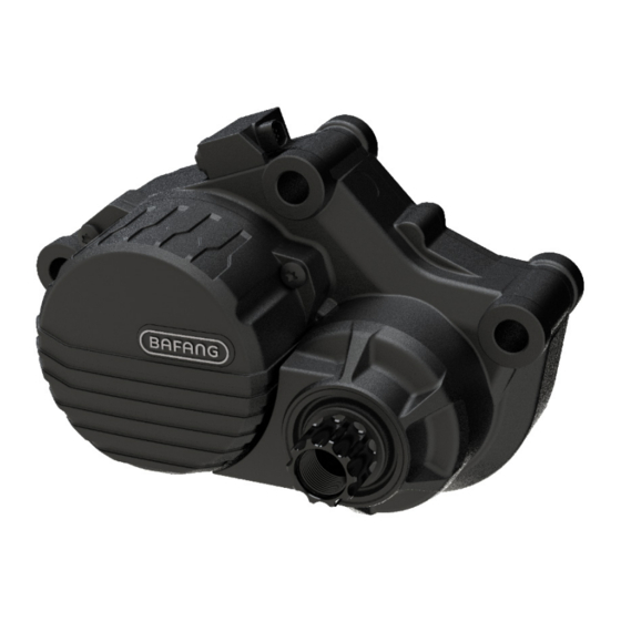
The following graphic, is the identification numbers of the product, which are shown on the housing: • Product Model MM G532.250.C Note: Content in the label is important informa- tion about this product. Please do not remove the information from the motor. -
Page 3: Specifications
6.2 SPECIFICATIONS Motor model: MM G532.250.C Rated power (W) Rated voltage (V) Waterproof IP65 Certification EMC / ISO13849 Outdoor Temperatures -20℃~45℃ 6.2.1 Outline and Geometric Size BF-DM-C-MM G532-EN November 2019... -
Page 4: Surface
6.2.2 Surface Shockproof black coating 6.2.3 Storage Information The pedelec should be stored in a ventilated dry room. Avoid storing the pedelec near strong magnetic objects. BF-DM-C-MM G532-EN November 2019... -
Page 5: Drive Unit Installation
Socket spanner drive unit To tighten/loosen M15 waterproof screws on the crank Internal hex wrench To tighten/loosen lock-nut on chain wheel BAFANG Tool Cross screwdriver To tighten/loosen screws on the speed sensor Star screwdriver 6.3.2 Cabling Female 8 pin connector at the drive unit... -
Page 6: Motor Installation
6.3.3 Motor Installation M8 bolts M8 Flat washer M8 Lock nuts Standard tool 1) Align the three mounting holes of the drive unit with the mounting holes in the bike frame. From the right of the bike frame insert three M8 bolts into the mounting holes in the bike frame and the drive unit. 2) From the left, use standard tool tighten the three M8 Lock nuts with flat washer on the bike frame. -
Page 7: Chain Wheel Installation
Lock ring BAFANG's tool Standard tool Put the chain wheel onto the spline shaft of the drive unit. Use BAFANG's tool to fasten the lock ring counterclockwise onto the spline shaft. Torque requirement: 35 N.m. 6.3.6 Crank Installation Left crank... -
Page 8: External Speed Sensor Installation
6.3.7 External Speed Sensor Installation Fasten the mounting screws through the speed sensor and with a cross screwdriver. Tightening the speed sensor onto the frame. Torque requirement: 1.5-2 N.m. (Note: Please make sure the gap between the speed sensor and the magnetic unit is between 10 and 20 mm.) Now place the magnet on the spoke of the wheel ensuring it is aligned to the middle of the speed sensor. -
Page 9: Maintenance
6.4 MAINTENANCE • Maintenance must be carried out by authorized personnel with the correct equipment. • Do not disassemble the motor. • Do not use thinners or other solvents to clean the components. Such substances can damage the surfaces. • Avoid water submerging, to keep the components protected. •...