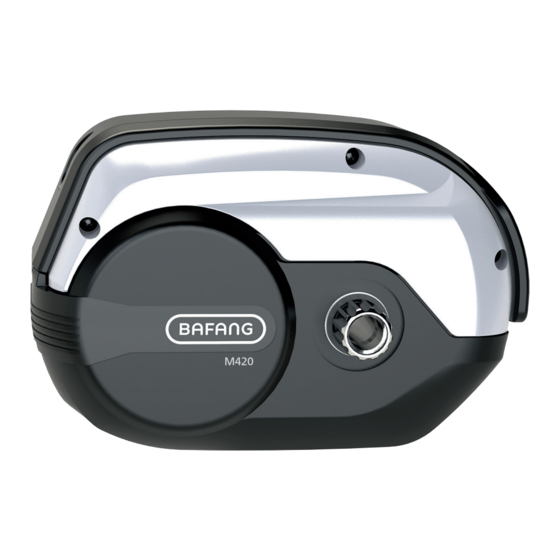
Summary of Contents for BAFANG M420
-
Page 1: Table Of Contents
6 DEALER MANUAL FOR M420 (MM G332.250/350.C/CCB) CONTENT 6.1 Introduction 6.3.2 Motor Installation 6.2 Specifications 6.3.3 Cabling 6.2.1 Outline and geometric size 6.3.4 Motor Cover Installation 6.3.5 Chain Wheel Installation 6.2.2 Surface 6.3.6 Crank Installation 6.2.3 Storage Information 6.3 Drive Unit Installation 6.3.7 External Speed Sensor Installation... -
Page 2: Introduction
MM G332.250.CCB MM G332.350.CCB • Scope Applies only to electrically powered pedelecs developed or licensed by Bafang. It is suitable for city and trekking bikes, which have been developed for road use. The engine is not suitable for sport competitions. -
Page 3: Specifications
6.2 SPECIFICATIONS ① Motor model: MM G332.250.C / MM G332.250.CCB Rated power (W) Rated voltage (V) 36 / 43 / 48 Waterproof IP65 Certification CE / ROHS / EN14766 Outdoor Temperatures -20℃~45℃ ② Motor model: MM G332.350.C / MM G332.350.CCB Rated power (W) Rated voltage (V) 36 / 43 / 48... -
Page 4: Surface
Chain line(CL): 45/48/49mm Shaft standard: BAFANG 6.2.2 Surface Shockproof black coating 6.2.3 Storage Information The pedelec should be stored in a ventilated dry room. Avoid storing the pedelec near strong magnetic objects. BF-DM-C-MM G332-EN October 2019... -
Page 5: Drive Unit Installation
6.3 DRIVE UNIT INSTALLATION 6.3.1 List of Tools to be used Do not use impact wrenches. Use of the Tools Tools To tighten/loosen the screw onto the frame adapter and the drive unit. Internal hex wrench To tighten/loosen screws on the crank. To tighten/loosen screws on the motor cover. -
Page 6: Cabling
The size of the standard tool for our company: outer diameter 17.7 and length 63. Tightening torque requirment: 35 N.m. Please pay attention to the direction of the cables coming out of the frame and from the motor. Please note that the cables should not be squashed when the motor is attached to the frame. - Page 7 6.3.3.3 Connection of the gear sensor to the motor The male connector from the motor The female connector from the gear sensor Please connect the connectors from the motor and the gear sensor together. 6.3.3.4 Connection of the speed sensor to the motor The female connector from the motor The male connector from the...
- Page 8 6.3.3.6 Connection of the headlight cable to the motor The male connector from the motor The female connector from the headlight cable Please connect the connectors from the motor and the headlight cable together. 6.3.3.7 Connection of the taillight cable to the motor The female connector from the motor The male connector from the...
-
Page 9: Motor Cover Installation
6.3.4 Motor Cover Installation M4*8 Cross countersunk head screws Motor cover As shown in the figure above, three M4*8 countersunk head screws are used to secure the motor cover on the motor. The covers purpose is to protect and hide the cables and connectors. Locking torque requirement :1.5N.m. -
Page 10: Crank Installation
6.3.6 Crank Installation Left crank Right crank Crank attachment screws Crank tightening screws M6*20 Mount the right crank on the right side of the axel, using a hex key tighten screw (C) onto the axel (torque requirement is 1.5N.m) , this ensures the crank stays attached.Now using a Hex key tighten two M6 * 20 (D) screws on the crank itself ensuring the crank is kept in place and cannot rotate around the axel (torque requirement is 15N.m). -
Page 11: External Speed Sensor Installation
6.3.7 External Speed Sensor Installation Speed sensor Magnet for the speed sensor Fasten the mounting screws through the speed sensor and with a cross screwdriver. Tightening the speed sensor onto the frame. Then place the rubber seal on the speed sensor hiding the screw. Torque requirement: 1.5-2 N.m. -
Page 12: Maintenance
6.4 MAINTENANCE • Maintenance must be carried out by autho- rized personnel with the correct equipment. • Do not disassemble the motor. • Do not use thinners or other solvents to clean the components. Such substances can damage the surfaces. •...


