Table of Contents
Advertisement
Quick Links
TI01503D/06/EN/02.21
71528716
2021-07-01
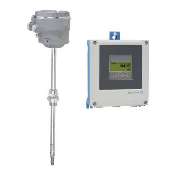
Insertion flowmeter with long-term stability as remote version with up to 4
I/Os
Application
• Measuring principle is characterized by a high operable flow
range and direct mass flow measurement
• Measurement of utility and process gases as well as gas
mixtures in circular piping or rectangular ducts
Device properties
• Insertion version for DN 80 to 1500 (3 to 60")
• Bidirectional measurement; high measuring performance
• Patented drift-free sensor with SIL 2
• Remote version with up to 4 I/Os
• Backlit display with touch control and WLAN access
• Standard cable between sensor and transmitter
Products
Technical Information
Proline t-mass I 500
Thermal mass flowmeter
Solutions
Your benefits
• Flexible, convenient programming based on 21 standard
gases or freely definable gas mixtures thereof
• High level of process control – premium measurement
accuracy and repeatability
• Reliable monitoring – detection of process disturbances and
reverse flow
• Flexible installation – suitable for large dimensional range
and circular pipes or rectangular ducts
• Full access to process and diagnostic information –
numerous, freely combinable I/Os and fieldbuses
• Reduced complexity and variety – freely configurable I/O
functionality
• Integrated verification – Heartbeat Technology
Services
Advertisement
Table of Contents

Related Manuals for Endress+Hauser Proline t-mass I 500


Summary of Contents for Endress+Hauser Proline t-mass I 500
- Page 1 Solutions Services TI01503D/06/EN/02.21 71528716 2021-07-01 Technical Information Proline t-mass I 500 Thermal mass flowmeter Insertion flowmeter with long-term stability as remote version with up to 4 I/Os Application Your benefits • Measuring principle is characterized by a high operable flow •...
-
Page 2: Table Of Contents
Proline t-mass I 500 Table of contents About this document ......Environment ......46 Symbols . - Page 3 Proline t-mass I 500 Accessories ....... 81 Device-specific accessories ..... .
-
Page 4: About This Document
Proline t-mass I 500 About this document Symbols Electrical symbols Symbol Meaning Direct current Alternating current Direct current and alternating current Ground connection A grounded terminal which, as far as the operator is concerned, is grounded via a grounding system. - Page 5 Proline t-mass I 500 Symbols in graphics Symbol Meaning 1, 2, 3, ... Item numbers , … Series of steps A, B, C, ... Views A-A, B-B, C-C, ... Sections Hazardous area Safe area (non-hazardous area) Flow direction Endress+Hauser...
-
Page 6: Function And System Design
Gas Engine The integrated Gas Engine functionality ensures maximum measuring performance for flow measurement. The Gas Engine developed by Endress+Hauser is a software-based database of typical standard gases and their specific properties. The Gas Engine calculates the properties of gas mixtures based on the percentage shares of up to 8 gas components. -
Page 7: Measuring System
Bidirectional measurement and reverse flow detection Conventional thermal mass flowmeters cannot distinguish between forward and reverse flows. They always record flow in both directions with the same algebraic sign. Endress+Hauser' s thermal flowmeter is available in this conventional unidirectional design, or as a bidirectional flowmeter. - Page 8 Proline t-mass I 500 Device versions and materials • Transmitter housing • Aluminum, coated: aluminum, AlSi10Mg, coated • Material: polycarbonate • Material of window in transmitter housing • Aluminum, coated: glass • Material: polycarbonate Configuration • External operation via 4-line, backlit, graphic local display with touch control and guided menus ("Make-it-run"...
-
Page 9: Equipment Architecture
Proline t-mass I 500 Equipment architecture A0027512 1 Possibilities for integrating measuring devices into a system Control system (e.g. PLC) Connecting cable (0/4 to 20 mA HART etc.) Fieldbus Coupler Non-hazardous area Hazardous area: Zone 2; Class I, Division 2 Hazardous area: Zone 1;... - Page 10 Proline t-mass I 500 Protecting access via hardware write protection Write access to the device parameters via the local display, Web browser or operating tool (e.g. FieldCare, DeviceCare) can be disabled via a write protection switch (DIP switch on the motherboard).
- Page 11 Proline t-mass I 500 The use of relevant industrial standards and guidelines that have been defined by national and international safety committees, such as IEC/ISA62443 or the IEEE, is recommended. This includes organizational security measures such as the assignment of access authorization as well as technical measures such as network segmentation.
-
Page 12: Input
Proline t-mass I 500 Input Measured variable Measured process variables • Mass flow • Temperature Calculated process variables • Corrected volume flow • Volume flow • FAD volume flow • Flow velocity • Calorific value • 2nd temperature heat difference •... - Page 13 Proline t-mass I 500 Full scale value [kg/h] Full scale value [Nm3/h] [mm] (Air, 20°C, 1.013 bar a) (Air, 0°C, 1.013 bar a) Minimum Maximum Minimum Maximum 1 000 3 260 326 000 2 521 252 105 1 500 7 335...
-
Page 14: Operable Flow Range
Proline t-mass I 500 • Order code for "Sensor version; sensor; insertion tube:", option SB "Bidirectional; stainless steel; stainless steel" • Order code for "Sensor version; sensor; insertion tube:", option SC "Reverse flow detection; stainless steel; stainless steel" Full scale value [lb/h]... - Page 15 Proline t-mass I 500 HART protocol The measured values are written from the automation system to the measuring device via the HART protocol. The pressure transmitter must support the following protocol-specific functions: • HART protocol • Burst mode Current input The measured values are written from the automation system to the measuring device via the current input →...
-
Page 16: Output And Input Variants
Proline t-mass I 500 Output Output and input variants Depending on the option selected for output/input 1, different options are available for the other outputs and inputs. Only one option can be selected for each output/input 1 to 4. The following tables must be read vertically (↓). - Page 17 Proline t-mass I 500 Output/input 1 and options for output/input 3 and 4 Options for output/input 2 → 16 Order code for "Output; input 1" (020) → Possible options Current output 4 to 20 mA HART Current output 4 to 20 mA HART Ex i passive ↓...
-
Page 18: Output Signal
Proline t-mass I 500 Output signal Current output 4 to 20 mA HART Order code "Output; input 1" (20): Option BA: current output 4 to 20 mA HART Signal mode Can be set to: • Active • Passive Current range Can be set to: •... - Page 19 Proline t-mass I 500 Damping Configurable: 0 to 999.9 s Assignable measured • Mass flow variables • Volume flow • Corrected volume flow • FAD volume flow • Flow velocity • Temperature • Energy flow • Pressure • Density • Heat flow •...
- Page 20 Proline t-mass I 500 Pulse/frequency/switch output Function Can be set to pulse, frequency or switch output Version Open collector Can be set to: • Active • Passive • Passive NAMUR Maximum input values DC 30 V, 250 mA (passive) Open-circuit voltage DC 28.8 V (active)
- Page 21 Proline t-mass I 500 Number of switching Unlimited cycles Assignable functions • Off • On • Diagnostic behavior • Limit value • Off • Mass flow • Volume flow • Corrected volume flow • FAD volume flow • Heat flow •...
-
Page 22: Signal On Alarm
Proline t-mass I 500 The technical values correspond to those of the inputs and outputs described in this section. Signal on alarm Depending on the interface, failure information is displayed as follows: HART current output Device diagnostics Device condition can be read out via HART Command 48... -
Page 23: Load
Proline t-mass I 500 Local display Plain text display With information on cause and remedial measures Backlight Red backlighting indicates a device error. Status signal as per NAMUR recommendation NE 107 Interface/protocol • Via digital communication: • HART protocol • Modbus RS485 •... -
Page 24: Low Flow Cut Off
Proline t-mass I 500 Order code Output type Safety-related values "Output; input 2"; Output; input 2 Output; input 3 Output; input 4 "Output; input 3" "Output; input 4" 24 (+) 25 (–) 22 (+) 23 (–) 20 (+) 21 (–) -
Page 25: Power Supply
Proline t-mass I 500 Data access Each device parameter can be accessed via Modbus RS485. For Modbus register information System integration Information on system integration: Operating Instructions . • Modbus RS485 information • Function codes • Register information • Response time •... -
Page 26: Pin Assignment, Device Plug
Proline t-mass I 500 Pin assignment, device plug Service interface Order code for "Accessories mounted", option NB: Adapter RJ45 M12 (service interface) Assignment Coding Plug/socket A0032047 Socket Recommended plug: • Binder, series 763, part no. 99 3729 810 04 •... -
Page 27: Electrical Connection
Proline t-mass I 500 Electrical connection Connection of connecting cable: Proline 500 – digital – 61 62 63 64 62 61 64 63 – A0028198 Cable entry for cable on transmitter housing Protective ground (PE) Connecting cable ISEM communication Grounding via ground connection; on device plug versions grounding is through the plug itself... - Page 28 Proline t-mass I 500 Connection examples Current output 4 to 20 mA HART 4...20 mA A0029055 2 Connection example for 4 to 20 mA HART current output (active) Automation system with current input (e.g. PLC) Cable shield provided at one end. The cable shield must be grounded at both ends to comply with EMC requirements;...
- Page 29 Proline t-mass I 500 HART input 4...20 mA A0028763 4 Connection example for HART input with a common negative (passive) Automation system with HART output (e.g. PLC) Active barrier for power supply (e.g. RN221N) Cable shield provided at one end. The cable shield must be grounded at both ends to comply with EMC requirements;...
- Page 30 Proline t-mass I 500 Current output 4-20 mA 4...20 mA A0028758 6 Connection example for 4-20 mA current output (active) Automation system with current input (e.g. PLC) Analog display unit: observe maximum load → 18 Transmitter 4...20 mA A0028759 ...
- Page 31 Proline t-mass I 500 Switch output A0028760 9 Connection example for switch output (passive) Automation system with switch input (e.g. PLC) Power supply Transmitter: Observe input values → 20 Relay output A0028760 10 Connection example for relay output (passive) Automation system with relay input (e.g.
-
Page 32: Terminals
Proline t-mass I 500 Status input A0028764 12 Connection example for status input Automation system with status output (e.g. PLC) Power supply Transmitter Terminals Spring-loaded terminals: Suitable for strands and strands with ferrules. Conductor cross-section 0.2 to 2.5 mm (24 to 12 AWG). - Page 33 Proline t-mass I 500 Current output 0/4 to 20 mA Standard installation cable is sufficient. Pulse/frequency/switch output Standard installation cable is sufficient. Relay output Standard installation cable is sufficient. Current input 0/4 to 20 mA Standard installation cable is sufficient.
- Page 34 Proline t-mass I 500 A: Connecting cable between sensor and transmitter: Proline 500 – digital Standard cable A standard cable with the following specifications can be used as the connecting cable. Design 4 cores (2 pairs); uninsulated stranded CU wires; pair-stranded with common...
- Page 35 Proline t-mass I 500 Cross-section Cable length [max.] Termination 2 x 2 x 0.50 mm 50 m (165 ft) 2 x 2 x 0.50 mm (AWG 20) (AWG 20) BN WT YE GN • +, – = 0.5 mm • A, B = 0.5 mm 3 x 2 x 0.50 mm...
-
Page 36: Performance Characteristics
Proline t-mass I 500 Performance characteristics Reference operating • Error limits based on ISO 11631 conditions • Dry air with +20 to +30 °C (+68 to +86 °F) at 0.8 to 1.5 bar (12 to 22 psi) • Specifications as per calibration protocol •... -
Page 37: Repeatability
Proline t-mass I 500 Accuracy of outputs The outputs have the following base accuracy specifications. Current output Accuracy ±5 µA Pulse/frequency output o.r. = of reading Accuracy Max. ±50 ppm o.r. (over the entire ambient temperature range) Repeatability ±0.25 % of the display value for velocities above 1.0 m/s (3.3 ft/s) Response time Typically <... -
Page 38: Installation
• For further information → ISO standard 14511. Insertion depth The minimum length of the insertion version can be determined using the Endress+Hauser Applicator program or with the calculation formula below. The calculated necessary insertion depth must be within the adjusting range of the selected insertion version. - Page 39 Insertion depth = (0.3⋅ A) + B + (C1 + C2) The insertion depth must be at least 100mm. Determining dimensions C1 and C2 If only Endress+Hauser mounting bosses are used Mounting boss 1" NPT C1 + C2 = 112 mm (4.409 in) Mounting boss G1"...
-
Page 40: Installation Conditions For Nipples
Proline t-mass I 500 Selecting the length of the insertion version Select the length of the insertion version using the calculated insertion depth and the following table. The insertion depth must be within the adjusting range of the insertion version. - Page 41 Proline t-mass I 500 • In the case of bidirectional sensors, also observe the recommended inlet run in the opposite direction. • If several flow disturbances are present, use flow conditioners. • Use flow conditioners if it is not possible to observe the required inlet runs.
- Page 42 Proline t-mass I 500 A0045846 21 The additional measured error to be expected without flow conditioners depending on the disturbance type and inlet run Additional measured error (%) Inlet run (DN) 2 × 90 ° elbow, 3-dimensional Expansion 2 × 90° elbow Reduction or 90°...
- Page 43 Proline t-mass I 500 5 × DN 5 × DN 10 × DN A0039424 22 Recommended inlet and outlet runs when using a flow conditioner Flow conditioner In the case of bidirectional sensors, also observe the inlet run in the opposite direction.
- Page 44 Proline t-mass I 500 Outlet runs with pressure measuring points Install the pressure measuring point downstream of the measuring system. This prevents the pressure transmitter from potentially affecting the flow in the measuring point. 2 ... 5 x DN A0039447 ...
-
Page 45: Mounting The Transmitter Housing
Proline t-mass I 500 Mounting the transmitter Proline 500 – digital transmitter housing Post mounting ø 20…70 TX 25 ø ( 0.79…2.75) SW 10 A0029051 25 Engineering unit mm (in) Wall mounting 17 (0.67) 5.8 (0.23) 5.8 (0.23) 149 (5.85) A0029054 ... -
Page 46: Environment
‣ If operating outdoors: Avoid direct sunlight, particularly in warm climatic regions. You can order a weather protection cover from Endress+Hauser→ 81. –50 to +80 °C (–58 to +176 °F), preferably at +20 °C (+68 °F) Storage temperature If a plastic transmitter housing is permanently exposed to certain steam and air mixtures, this can Atmosphere damage the housing. -
Page 47: Interior Cleaning
Proline t-mass I 500 Transmitter • 10 to 200 Hz, 0.01 g • 200 to 2 000 Hz, 0.003 g • Total: 2.70 g rms Shock half-sine, according to IEC 60068-2-27 • Sensor 6 ms 30 g • Transmitter 6 ms 50 g... -
Page 48: Process
Proline t-mass I 500 Process Medium temperature range Sensor –40 to +180 °C (–40 to +356 °F) Seals • Sealing rings: • EPDM –40 to +140 °C (–40 to +284 °F) • FKM –40 to +180 °C (–40 to +356 °F) •... -
Page 49: Pressure Loss
Proline t-mass I 500 The maximum flow depends on the gas type and the pipe nominal diameter used. The end of the measuring range is reached when the Mach number listed below is reached. Mach Order code number • Order code for "Sensor version; sensor; insertion tube:", option SB "Bidirectional; stainless steel;... -
Page 50: Cold Tap, Ambient Pressure
Proline t-mass I 500 NOTICE Danger of overheating when heating ‣ Ensure that the temperature at the lower end of the transmitter housing does not exceed 80 °C (176 °F). ‣ Ensure that sufficient convection takes place at the transmitter neck. - Page 51 Proline t-mass I 500 Mechanical construction Dimensions in SI units Housing of Proline 500 – digital transmitter Non-hazardous area or hazardous area: Zone 2; Class I, Division 2 A0033789 Order code for "Transmitter housing", option A "Aluminum, coated" and order code for "Integrated ISEM electronics", option A "Sensor"...
- Page 52 Proline t-mass I 500 Order code for "Sensor connection housing", option A "Aluminum, coated" [mm] [mm] [mm] [mm] Depending on the cable gland used: values up to + 30 mm Order code for "Sensor connection housing", option L "Cast, stainless"...
-
Page 53: Hot Tap, Process Pressure
Proline t-mass I 500 Cold tap, ambient pressure 40 (1.6) 30 (1.2) 38.1 (1.5) A0042224 30 Dimensions: mm (in) Order code for "Accessory enclosed", option "Welding socket" Order code for "Accessory enclosed": • Option PR "Cold tap G 1", ambient pressure"... - Page 54 Proline t-mass I 500 A0041359 31 Versions available for order Safety chain for low-pressure version Sensor connection Ball valve Retrofit adapter (for subsequent installation with existing welding socket (DK6MB)) Welding socket (DK6MB) only G1" / 1" NPT Process connection welding socket...
- Page 55 Proline t-mass I 500 Extractor assembly for medium-pressure version Order code for "Accessory enclosed": • Option PI "Hot tap G 1", medium pressure maximum 16 bar/230 psig" • Option PJ "Hot tap 1" NPT, medium pressure maximum 16 bar/230 psig"...
- Page 56 Proline t-mass I 500 Used in combination with flanges according to DIN EN 1092-1: PN 10 1.4404 (316, 316L) Can be ordered separately as an "Accessory": DK6004 Centering diameter / D2 [mm] [mm] [mm] 330.0 33.0 380.0 39.6 The flow conditioner is fitted at the outer diameter between the bolts.
- Page 57 Proline t-mass I 500 Used in combination with flanges according to DIN EN 1092-1: PN 40 1.4404 (316, 316L) Can be ordered separately as an "Accessory": DK6004 Centering diameter / D2 [mm] [mm] [mm] 355.0 33.0 420.0 39.6 The flow conditioner is fitted at the outer diameter between the bolts.
- Page 58 Proline t-mass I 500 Used in combination with flanges according to JIS B2220: 10K 1.4404 (316, 316L) Can be ordered separately as an "Accessory": DK6004 Centering diameter / D2 [mm] [mm] [mm] 330.0 33.0 380.0 39.6 The flow conditioner is fitted at the outer diameter between the bolts.
-
Page 59: Dimensions In Us Units
Proline t-mass I 500 Proline 500 – digital External WLAN antenna mounted on device A0033607 34 Engineering unit mm (in) External WLAN antenna mounted with cable The external WLAN antenna can be mounted separately from the transmitter if the transmission/ reception conditions at the transmitter mounting location are poor. - Page 60 Proline t-mass I 500 A0033789 Order code for "Transmitter housing", option A "Aluminum, coated" and order code for "Integrated ISEM electronics", option A "Sensor" [in] [in] [in] [in] [in] [in] 6.57 9.13 3.50 7.36 0.94 0.83 Order code for "Transmitter housing", option D "Polycarbonate" and order code for "Integrated ISEM electronics", option A "Sensor"...
- Page 61 Proline t-mass I 500 Order code for "Sensor connection housing", option L "Cast, stainless" [in] [in] [in] [in] 5.71 3.39 2.32 5.35 Depending on the cable gland used: values up to + 1.18 in Order code for "Sensor connection housing", option A "Aluminum, coated"...
- Page 62 Proline t-mass I 500 Cold tap, ambient pressure 40 (1.6) 30 (1.2) 38.1 (1.5) A0042224 36 Dimensions: mm (in) Order code for "Accessory enclosed", option "Welding socket" Order code for "Accessory enclosed": • Option PR "Cold tap G 1", ambient pressure"...
- Page 63 Proline t-mass I 500 A0041359 37 Versions available for order Safety chain for low-pressure version Sensor connection Ball valve Retrofit adapter (for subsequent installation with existing welding socket (DK6MB)) Welding socket (DK6MB) only G1" / 1" NPT Process connection welding socket...
- Page 64 Proline t-mass I 500 Extractor assembly for medium-pressure version Order code for "Accessory enclosed": • Option PI "Hot tap G 1", medium pressure maximum 16 bar/230 psig" • Option PJ "Hot tap 1" NPT, medium pressure maximum 16 bar/230 psig"...
- Page 65 Proline t-mass I 500 Used in combination with flanges according to ASME B16.5: Class 150 1.4404 (316, 316L) Can be ordered separately as an "Accessory": DK6004 Centering diameter / D2 [in] [in] [in] 13.40 1.30 15.90 1.56 The flow conditioner is fitted at the outer diameter between the bolts.
-
Page 66: Materials
Proline t-mass I 500 Proline 500 – digital External WLAN antenna mounted on device A0033607 40 Engineering unit mm (in) External WLAN antenna mounted with cable The external WLAN antenna can be mounted separately from the transmitter if the transmission/ reception conditions at the transmitter mounting location are poor. - Page 67 Proline t-mass I 500 Sensor connection housing Order code for "Sensor connection housing": • Option A "Aluminum coated": aluminum, AlSi10Mg, coated • Option L "Cast, stainless": 1.4409 (CF3M) similar to 316L Cable entries/cable glands A0020640 42 Possible cable entries/cable glands Female thread M20 ×...
-
Page 68: Weight
For aggressive media (e.g. chlorine or ozone), we recommend special materials (Alloy for sensing element, PVDF or 1.4404 for ferrules and FKM for flat seal). For any requests, please contact the Endress+Hauser sales organization responsible for your area. Sensor guard Stainless steel, 1.4404 (316/316L) -
Page 69: Process Connections
Proline t-mass I 500 Weight in US units Installed length [in] Weight [lbs] Process connections • G¾", ISO 228/1 compression fitting • G1", ISO 228/1, compression fitting • ¾" NPT, compression fitting • 1" NPT, compression fitting For information on the different materials used in the process connections → 67... -
Page 70: Remote Operation
Proline t-mass I 500 Display elements • 4-line, illuminated, graphic display • White background lighting; switches to red in event of device errors • Format for displaying measured variables and status variables can be individually configured • Permitted ambient temperature for the display: –20 to +60 °C (–4 to +140 °F) The readability of the display may be impaired at temperatures outside the temperature range. -
Page 71: Service Interface
Proline t-mass I 500 A0028746 44 Options for remote operation via HART protocol (passive) Control system (e.g. PLC) Transmitter power supply unit, e.g. RN221N (with communication resistor) Connection for Commubox FXA195 and Field Communicator 475 Field Communicator 475 Computer with Web browser (e.g. Internet Explorer) for access to the integrated device Web server or computer with an operating tool (e.g. -
Page 72: Supported Operating Tools
Proline t-mass I 500 Proline 500 – digital transmitter open press A0029163 46 Connection via service interface (CDI-RJ45) Computer with Web browser (e.g. Microsoft Internet Explorer, Microsoft Edge) for accessing the integrated device Web server or with "FieldCare", "DeviceCare" operating tool with COM DTM "CDI Communication TCP/IP"... - Page 73 Proline t-mass I 500 Supported operating Operating unit Interface Additional information tools Web browser Notebook, PC or tablet • CDI-RJ45 service Special Documentation for with Web browser interface device • WLAN interface DeviceCare SFE100 Notebook, PC or tablet • CDI-RJ45 service →...
-
Page 74: Historom Data Management
Proline t-mass I 500 HistoROM data management The measuring device features HistoROM data management. HistoROM data management comprises both the storage and import/export of key device and process data, making operation and servicing far more reliable, secure and efficient. When the device is delivered, the factory settings of the configuration data are stored as a backup in the device memory. - Page 75 Proline t-mass I 500 Data logging Manual If the Extended HistoROM application package (order option) is enabled: • Record up to 1 000 measured values via 1 to 4 channels • User configurable recording interval • Record up to 250 measured values via each of the 4 memory channels •...
-
Page 76: Certificates And Approvals
The device meets the legal requirements of the applicable EU Directives. These are listed in the corresponding EU Declaration of Conformity along with the standards applied. Endress+Hauser confirms successful testing of the device by affixing to it the CE mark. RCM-tick symbol The measuring system meets the EMC requirements of the "Australian Communications and Media... -
Page 77: Functional Safety
Proline t-mass I 500 IS (Ex nA, Ex i) Transmitter Sensor Class I Division 2 Groups A - D Class I, II, III Division 1 Groups A-G NI (Ex nA) Transmitter Sensor Class I Division 2 Groups A - D... -
Page 78: Other Standards And Guidelines
Requirements for field devices for standard applications Classification of process Endress+Hauser devices are designed in accordance with ANSI/ISA 12.27.01. allowing the user to sealing between electrical waive the use and save the cost of installing external secondary process seals in the conduit as required by the process sealing sections of ANSI/NFPA 70 (NEC) and CSA 22.1 (CEC). -
Page 79: Ordering Information
• Depending on the device: Direct input of measuring point-specific information such as measuring range or operating language • Automatic verification of exclusion criteria • Automatic creation of the order code and its breakdown in PDF or Excel output format • Ability to order directly in the Endress+Hauser Online Shop Endress+Hauser... -
Page 80: Application Packages
The application packages can be ordered with the device or subsequently from Endress+Hauser. Detailed information on the order code in question is available from your local Endress+Hauser sales center or on the product page of the Endress+Hauser website: www.endress.com. -
Page 81: Accessories
Proline t-mass I 500 Accessories Various accessories, which can be ordered with the device or subsequently from Endress+Hauser, are available for the device. Detailed information on the order code in question is available from your local Endress+Hauser sales center or on the product page of the Endress+Hauser website: www.endress.com. - Page 82 Proline t-mass I 500 Display guard Is used to protect the display against impact or scoring, for example from sand in Proline 500 – digital desert areas. Order number: 71228792 Installation Instructions EA01093D Connecting cable The connecting cable can be ordered directly with the measuring device (order code Proline 500 –...
-
Page 83: Communication-Specific Accessories
Proline t-mass I 500 Hot tap (medium Order code for "Accessory enclosed" pressure) • Option PI "Hot tap G1", medium pressure max. 16 bar/230 psig" • Option PJ "Hot tap 1" NPT, medium pressure max. 16 bar/230 psig" • Option PM "Hot tap G¾", medium pressure max. 16 bar/230 psig"... -
Page 84: Service-Specific Accessories
Accessories Description Applicator Software for selecting and sizing Endress+Hauser measuring devices: • Choice of measuring devices with industrial requirements • Calculation of all the necessary data for identifying the optimum flowmeter: e.g. nominal diameter, pressure loss, flow velocity and accuracy. -
Page 85: Supplementary Documentation
For an overview of the scope of the associated Technical Documentation, refer to the following: • W@M Device Viewer (www.endress.com/deviceviewer): Enter the serial number from the nameplate • Endress+Hauser Operations App: Enter the serial number from the nameplate or scan the 2D matrix code (QR code) on the nameplate Standard documentation... -
Page 86: Registered Trademarks
Proline t-mass I 500 Contents Documentation code INMETRO Ex ec XA01501D NEPSI Ex i XA01502D NEPSI Ex nA XA01503D Functional Safety Manual Contents Documentation code Proline t-mass 500 SD02484D Special documentation Contents Documentation code HART Modbus RS485 Functional Safety Manual SD02484D –... - Page 88 *71528716* 71528716 www.addresses.endress.com...