
Related Manuals for Endress+Hauser Cubemass DCI


Summary of Contents for Endress+Hauser Cubemass DCI
- Page 1 Operating Instructions Cubemass DCI MODBUS RS485 Coriolis mass flow measuring system BA141D/06/en/04.10 71112148 valid as of version V 3.06.00 (Device software)
-
Page 3: Table Of Contents
Cubemass DCI MODBUS RS485 Table of contents Table of contents Safety instructions ....5 Operation ..... . 26 Designated use . - Page 4 Cubemass DCI MODBUS RS485 Table of contents Maintenance ....65 External cleaning ......65 Accessories .
-
Page 5: Safety Instructions
• The device must be operated by persons authorized and trained by the facility's owner-operator. Strict compliance with the instructions in the Operating Instructions is mandatory. • Endress+Hauser will be happy to assist in clarifying the corrosion resistance properties of materials wetted by special fluids, including fluids used for cleaning. However, small changes of temperature, concentration or degree of contamination in the process can result in differences in corrosion resistance. -
Page 6: Return
Endress+Hauser: • Always enclose a duly completed "Declaration of Contamination" form. Only then can Endress+Hauser transport, examine and repair a returned device. • Enclose special handling instructions if necessary, for example a safety data sheet as per Regulation (EC) 1907/2006 REACH. -
Page 7: Identification
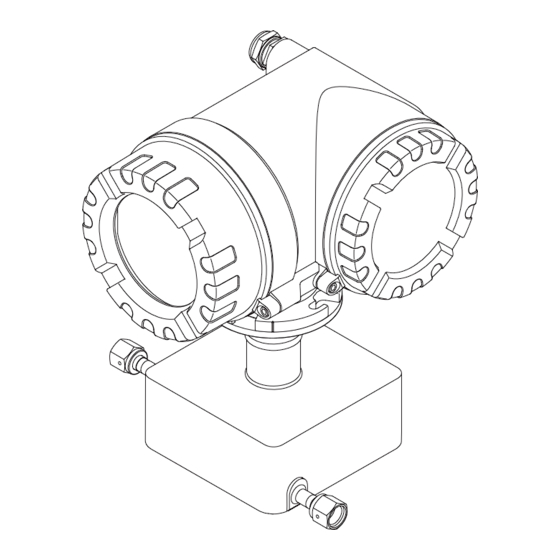
Cubemass DCI MODBUS RS485 Identification Identification Device designation The "Cubemass DCI" flow measuring system consists of the following components: • Transmitter • Sensor Two versions are available: • Compact version: transmitter and sensor form a single mechanical unit. • Remote version: transmitter and sensor are installed separately. -
Page 8: Nameplate Of The Sensor
Identification Cubemass DCI MODBUS RS485 2.1.2 Nameplate of the sensor IP67 / NEMA/Type4X Sensor C (Cubemass DCI) 8CN04-XXXXXXXXXXXX Order Code: 12345678901 Ser.No.: -20°C(-4°F)<Tamb<+60°C(140°F) 1234567890123 Ident No.: 1.0000 / 00 K-factor: DN04 / 1/8" Cajon 4-VCO-4 p max.: = 160bar / 2320psi 25bar / 362.5psi Container... -
Page 9: Nameplate For Connections
Cubemass DCI MODBUS RS485 Identification 2.1.3 Nameplate for connections active See operating manual passive Betriebsanleitung beachten normally open contact Observer manuel d'instruction normally closed contact XXXXXXXXXXX Ser.No.: L1/L+ Supply / Versorgung / N/L- Tension d'alimentation 26 = B (RxD/TxD-P) 27 = A (RxD/TxD-N) MODBUS RS485 3…30VDC, Ri = 3 kOhm... -
Page 10: Additional Sign - Position Of The Rupture Disk
EMC requirements of IEC/EN 61326. The measuring system described in these Operating Instructions thus complies with the statutory requirements of the EC Directives. Endress+Hauser confirms successful testing of the device by affixing to it the CE mark. -
Page 11: Installation
Cubemass DCI MODBUS RS485 Installation Installation Incoming acceptance, transport and storage 3.1.1 Incoming acceptance On receipt of the goods, check the following points: • Is the packaging or content damaged? • Is anything missing from the shipment and does the scope of supply match your order? 3.1.2... -
Page 12: Mounting Location
Installation Cubemass DCI MODBUS RS485 3.2.2 Mounting location The accumulation of air and the formation of gas bubbles in the measuring tube could result in an increase in measuring errors. For this reason, avoid the following mounting locations in the pipe: •... -
Page 13: Orientation
Cubemass DCI MODBUS RS485 Installation System pressure It is important to ensure that cavitation does not occur as it could influence the oscillation of the measuring tube. No special measures need to be taken for fluids which have properties similar to water under normal conditions. -
Page 14: Heating
Installation Cubemass DCI MODBUS RS485 3.2.4 Heating Some fluids require suitable measures to avoid loss of heat at the sensor. Heating can be electric, e.g. with heated elements, or by means of heating jackets or copper pipes conveying hot water or steam. -
Page 15: Installation Instructions
Cubemass DCI MODBUS RS485 Installation Installation instructions 3.3.1 Turning the transmitter housing Turning the aluminum field housing Warning! The turning mechanism in devices with EEx d/de or NEC/CEC Cl. I Div. 1 classification is not the same as that described here. The procedure for turning these housings is described in the Ex-specific documentation. -
Page 16: Installing The Wall-Mount Housing
Installation Cubemass DCI MODBUS RS485 3.3.2 Installing the wall-mount housing There are various ways of installing the wall-mount housing: • Mounted directly on the wall • Installation in control panel (separate mounting set, accessories) → ä 17 • Pipe mounting (separate mounting set, accessories) → ä 17 "... - Page 17 Cubemass DCI MODBUS RS485 Installation Installation in control panel Prepare the opening in the panel → å 10. Slide the housing into the opening in the panel from the front. Screw the fasteners onto the wall-mount housing. Screw the threaded rods into the holders and tighten them until the housing is secured on the panel wall.
-
Page 18: Turning The Local Display
Installation Cubemass DCI MODBUS RS485 3.3.3 Turning the local display Unscrew cover of the electronics compartment from the transmitter housing. Press the side latches on the display module and remove the module from the electronics compartment cover plate. Rotate the display to the desired position (max. 4 × 45 ° in both directions), and reset it onto the electronics compartment cover plate. -
Page 19: Wiring
Wiring Warning! When connecting Ex-certified devices, see the notes and diagrams in the Ex-specific supplement to these Operating Instructions. Please do not hesitate to contact your Endress+Hauser sales office if you have any questions. Note! The measuring device does not have an internal disconnecting device. Therefore, assign a switch or circuit breaker to the measuring device with which the voltage supply line can be disconnected from the power system. -
Page 20: Shielding And Grounding
Wiring Cubemass DCI MODBUS RS485 4.1.1 Shielding and grounding When planning the shielding and grounding for a fieldbus system, there are three important points to consider: • Electromagnetic compatibility (EMC) • Explosion protection • Employee safety To ensure the optimum electromagnetic compatibility of systems, it is important that the system components and above all the cables, which connect the components, are shielded and that no portion of the system is unshielded. -
Page 21: Connecting The Remote Version
Cubemass DCI MODBUS RS485 Wiring Connecting the remote version 4.2.1 Connecting the connecting cable for sensor/transmitter Warning! • Risk of electric shock. Switch off the power supply before opening the device. Do not install or wire the device while it is connected to the power supply. -
Page 22: Connecting The Measuring Unit
Wiring Cubemass DCI MODBUS RS485 Connecting the measuring unit 4.3.1 Transmitter connection Warning! • Risk of electric shock. Switch off the power supply before opening the device. Do not install or wire the device while it is connected to the power supply. - Page 23 Cubemass DCI MODBUS RS485 Wiring (L–) B (RxD/TxD-P) (L+) A (RxD/TxD-N) A (RxD/TxD-N) B (RxD/TxD-P) + – + – + – – 24 25 26 27 20 21 22 23 – – N (L-) L1 (L+) A0002591 Fig. 14: Connecting the transmitter, cable cross-section: max. 2.5 mm...
-
Page 24: Terminal Assignment
Wiring Cubemass DCI MODBUS RS485 4.3.2 Terminal assignment Electrical values for inputs → ä 83. Electrical values for outputs → ä 84. Terminal No. (inputs/outputs) Order version 20 (+) / 21 (-) 22 (+) / 23 (-) 24 (+) / 25 (-) 26 (+) / 27 (–) -
Page 25: Post-Connection Check
Cubemass DCI MODBUS RS485 Wiring Post-connection check Perform the following checks after completing electrical installation of the measuring device: Device condition and specifications Notes Are cables or the device damaged (visual inspection)? – Electrical connection Notes Does the supply voltage match the specifications on the nameplate? -
Page 26: Operation
Operation Cubemass DCI MODBUS RS485 Operation Display and operating elements The local display enables you to read all important parameters directly at the measuring point and configure the device using the "Quick Setup" or the function matrix. The display consists of four lines; this is where measured values and/or status variables (direction of flow, empty pipe, bar graph etc.) are displayed. -
Page 27: Readings Displayed (Operation Mode)
Cubemass DCI MODBUS RS485 Operation 5.1.1 Readings displayed (operation mode) The display area consists of three lines in all; this is where measured values are displayed, and/or status variables (direction of flow, bar graph etc.). You can change the assignment of display lines to different variables to suit your needs and preferences (È... -
Page 28: Icons
Operation Cubemass DCI MODBUS RS485 5.1.3 Icons The icons which appear in the field on the left make it easier to read and recognize measured variables, device status, and error messages. Icon Meaning Icon Meaning System error Process error Fault message... -
Page 29: Brief Guide To The Function Matrix
Cubemass DCI MODBUS RS485 Operation Brief guide to the function matrix Note! • See the general notes → ä 30 • Function descriptions → see the "Description of Device Parameters" manual HOME position → F → Entry into the function matrix Select a block (e.g. -
Page 30: General Notes
• If programming is disabled and the P operating elements are pressed in any function, a prompt for the code automatically appears on the display. • If "0" is entered as the customer's code, programming is always enabled! • Your Endress+Hauser representative can be of assistance if you mislay your personal code. " Caution! Changing certain parameters such as all sensor characteristics, for example, influences numerous functions of the entire measuring system, particularly measuring accuracy. -
Page 31: Error Messages
Cubemass DCI MODBUS RS485 Operation Error messages 5.3.1 Type of error Errors that occur during commissioning or measuring are displayed immediately. If two or more system or process errors occur, the error with the highest priority is the one shown on the display. -
Page 32: Confirming Error Messages
Operation Cubemass DCI MODBUS RS485 5.3.3 Confirming error messages For the sake of plant and process safety, the measuring device can be configured in such a way that fault messages displayed ($) always have to be rectified and acknowledged locally by pressing F. - Page 33 Cubemass DCI MODBUS RS485 Operation Master/slave communication A distinction is made between two methods of communication with regard to master/slave communication via MODBUS RS485: • Polling (request-response-transaction) The master sends a request telegram to one slave and waits for the slave's response telegram.
-
Page 34: Modbus Telegram
Operation Cubemass DCI MODBUS RS485 5.4.2 MODBUS telegram General The master-slave process is used for data exchange. Only the master can initiate data transmission. Following the prompt, the slave sends the master the necessary data as a response telegram or executes the command requested by the master. -
Page 35: Modbus Function Codes
Cubemass DCI MODBUS RS485 Operation 5.4.3 MODBUS function codes The function code determines which read, write and test operations should be executed by means of the MODBUS protocol. The measuring device supports the following function codes: Function Name in accordance... -
Page 36: Modbus Register Addresses
Operation Cubemass DCI MODBUS RS485 5.4.5 MODBUS register addresses Each device parameter has its own register address. The MODBUS master uses this register address to talk to the individual device parameters and access the device data. The register addresses of the individual device parameters can be found in the "Description of Device Parameters"... - Page 37 Cubemass DCI MODBUS RS485 Operation Data types The following data types are supported by the measuring device: • FLOAT (floating-point numbers IEEE 754) Data length = 4 bytes (2 registers) Byte 3 Byte 2 Byte 1 Byte 0 SEEEEEEE EMMMMMMM...
-
Page 38: Modbus Error Messages
Operation Cubemass DCI MODBUS RS485 INTEGER: Sequence Selection 1 – 0 – 3 – 2 * Byte 1 Byte 0 3 – 2 – 1 – 0 (MSB) (LSB) 0 – 1 – 2 – 3 Byte 0 Byte 1 2 –... -
Page 39: Modbus Auto-Scan Buffer
Cubemass DCI MODBUS RS485 Operation 5.4.7 MODBUS auto-scan buffer Function description The MODBUS master uses the request telegram to access the device parameters (data) of the measuring device. Depending on the function code, the master gains read or write access to a single device parameter or a group of consecutive device parameters. - Page 40 Operation Cubemass DCI MODBUS RS485 Scan list MODBUS configuration Configuration via Register address local operation / configuration program (BASIC FUNCTION → MODBUS RS485 →) (data type = Integer) 5012 SCAN LIST REG. 12 5013 SCAN LIST REG. 13 5014 SCAN LIST REG. 14 5015 SCAN LIST REG.
- Page 41 Cubemass DCI MODBUS RS485 Operation Response time The response time when accessing the data area (register addresses 5051 to 5081) is typically between 3 and 5 ms. Note! It may take longer for a command to be executed in the device. The data is not updated until the command has been executed.
- Page 42 Operation Cubemass DCI MODBUS RS485 2. Access to data via MODBUS By specifying the register start address 5051 and the number of registers, the MODBUS master can read out the measured values with just one request telegram. Data area Access via MODBUS...
-
Page 43: Operating Options
The Fieldcheck tester/simulator is used for testing flowmeters in the field. When used in conjunction with the FieldCare software package, test results can be imported into a database, printed out and used for official certification. Contact your Endress+Hauser representative for more information. -
Page 44: Switching Hardware Write Protection On/Off
Operation Cubemass DCI MODBUS RS485 Switching hardware write protection on/off A jumper on the I/O board provides the means of switching hardware write protection on or off. When the write protection is switched on, it is not possible to write to the device parameters via MODBUS RS485. -
Page 45: Commissioning
Cubemass DCI MODBUS RS485 Commissioning Commissioning Function check Make sure that all the final checks have been completed before commissioning the measuring point: • Checklist for "Post-installation check" → ä 18. • Checklist for "Post-connection check" → ä 25. Switching on the measuring device If the post-connection checks have been performed, the supply voltage can be switched on. -
Page 46: Quick Setup
Commissioning Cubemass DCI MODBUS RS485 Quick Setup In the case of measuring devices without a local display, the individual parameters and functions must be configured via the configuration program, e.g. FieldCare. If the measuring device is equipped with a local display, all the important device parameters for standard operation can be configured quickly and easily by means of the "Commissioning"... - Page 47 Cubemass DCI MODBUS RS485 Commissioning 1002 Quick XXX.XXX.XX Setup Commission 2000 Language HOME POSITION Pre-setting Selection pre-settings Deliver Settings Actual Settings Selection system units Density Temperature Mass flow Volume flow Corr. Vol. flow Quit 0400 0402 0404 0420 0422 Unit...
-
Page 48: Quick Setup "Pulsating Flow
Commissioning Cubemass DCI MODBUS RS485 6.3.2 Quick Setup "Pulsating Flow" Note! The "Pulsating Flow" Quick Setup is only available if the device has a current output or a pulse/ frequency output. Certain types of pump such as reciprocating, peristaltic and cam-type pumps, for example, create a flow characterized by severe periodic fluctuations. - Page 49 Cubemass DCI MODBUS RS485 Commissioning Performing the "Pulsating flow" Quick Setup This Quick Setup menu guides you systematically through the setup procedure for all the device functions that have to be parameterized and configured for measuring pulsating flows. Note that this has no effect on values configured beforehand, such as measuring range, current range or full scale value.
- Page 50 Commissioning Cubemass DCI MODBUS RS485 Note! • The display returns to the function QUICK SETUP PULSATING FLOW (1003) if you press the Q key combination. • You can call up the Setup menu either directly from the "COMMISSIONING" Quick Setup menu or manually by means of the function QUICK SETUP PULSATING FLOW (1003).
-
Page 51: Quick Setup "Gas Measurement
Cubemass DCI MODBUS RS485 Commissioning 6.3.3 Quick Setup "Gas measurement" The measuring device is primarily designed for measuring liquid flow. The measurement of gases is also possible. Note! • Before carrying out the Quick Setup "Gas measurement", the Quick Setup "Commissioning" has to be executed. -
Page 52: Quick Setup "Communication
Commissioning Cubemass DCI MODBUS RS485 6.3.4 Quick Setup "Communication" To establish serial data transfer, various arrangements between the MODBUS master and MODBUS slave are required which have to be taken into consideration when configuring various functions. These functions can be configured quickly and easily by means of the "Communication" Quick Setup. - Page 53 Cubemass DCI MODBUS RS485 Commissioning Quick Setup "Communication" 6304 PARITY Selection depends on the "Data transfer mode" function: NONE; EVEN; UNEVEN • Available in the ASCII transfer mode → even or uneven parity bit (EVEN, UNEVEN). • Available in the RTU transfer mode → no parity bit (NONE) or even or uneven parity bit (EVEN, UNEVEN).
-
Page 54: Data Back-Up/Transfer
Commissioning Cubemass DCI MODBUS RS485 6.3.5 Data back-up/transfer You can use the T-DAT SAVE/LOAD function to transfer data (device parameters and settings) between the T-DAT (removable memory) and the EEPROM (device memory). This is required for the following applications: • Creating a backup: current data are transmitted from an EEPROM to the T-DAT. -
Page 55: Configuration
Cubemass DCI MODBUS RS485 Commissioning Configuration Warning! In the case of explosion-protected equipment, observe a cooling or discharge time of 10 minutes before opening the device. 6.4.1 Configuring the device address The device address must always be configured for a MODBUS slave. The valid device addresses are in a range from 1 to 247. -
Page 56: Configuring The Terminating Resistors
Commissioning Cubemass DCI MODBUS RS485 6.4.2 Configuring the terminating resistors It is important to terminate the MODBUS RS485 line correctly at the start and end of the bus segment since impedance mismatch results in reflections on the line which can cause faulty communication transmission. -
Page 57: Current Output: Active/Passive
Cubemass DCI MODBUS RS485 Commissioning 6.4.3 Current output: active/passive The current output is configured as "active" or "passive" by means of various jumpers on the current submodule. Warning! Risk of electric shock. Exposed components carry dangerous voltages. Make sure that the power supply is switched off before you remove the cover of the electronics compartment. -
Page 58: Pulse/Frequency Output
Commissioning Cubemass DCI MODBUS RS485 6.4.4 Pulse/frequency output The configuration of the pulse/frequency output with line monitoring "On" or "Off" takes place by means of various jumpers on the pulse/frequency output submodule. Warning! Risk of electric shock. Exposed components carry dangerous voltages. -
Page 59: Relay Contacts: Normally Closed/Normally Open
Cubemass DCI MODBUS RS485 Commissioning 6.4.5 Relay contacts: Normally closed/Normally open The relay contact can be configured as normally open (NO or make) or normally closed (NC or break) contacts by means of two jumpers on the pluggable submodule. This configuration can be called up at any time with the ACTUAL STATUS RELAY (4740) function. -
Page 60: Adjustment
The zero point obtained in this way is printed on the nameplate. Calibration takes place under reference operating conditions → ä 86. Consequently zero point adjustment is generally not necessary for Cubemass DCI! Experience shows that the zero point adjustment is advisable only in special cases: •... -
Page 61: Density Adjustment
Cubemass DCI MODBUS RS485 Commissioning Performing a zero point adjustment Operate the system until operating conditions have settled. Stop the flow (v = 0 m/s). Check the shutoff valves for leaks. Check that operating pressure is correct. Using the local display, select the ZEROPOINT ADJUSTMENT function in the function matrix: BASIC FUNCTIONS →... - Page 62 6484 MEASURE FLUID 1 The message "DENSITY MEASUREMENT RUNNING" appears on the display for approximately 10 seconds. During this time Cubemass DCI measures the current density of the first fluid (actual density value). Æ For 2-point density adjustment only: Use P to enter the target density of the second fluid and press F to save...
-
Page 63: Rupture Element
Cubemass DCI MODBUS RS485 Commissioning Rupture element Sensor housings with an integrated rupture element are optionally available. Warning! • Make sure that the function of the rupture element is not impeded by the installation. The triggering pressure in the housing is indicated on the information notice. -
Page 64: Memory (Historom)
Cubemass DCI MODBUS RS485 Memory (HistoROM) At Endress+Hauser, the term HistoROM refers to various types of data storage modules on which process and measuring device data are stored. By unplugging and plugging such modules, device configurations can be duplicated onto other measuring devices, to cite just one example. -
Page 65: Maintenance
Cubemass DCI MODBUS RS485 Maintenance Maintenance No special maintenance work is required. External cleaning When cleaning the exterior of measuring devices, always use cleaning agents that do not attack the surface of the housing and the seals. Endress+Hauser... -
Page 66: Accessories
Accessories Cubemass DCI MODBUS RS485 Accessories Various accessories, which can be ordered separately from Endress+Hauser, are available for the transmitter and the sensor. Detailed information on the order code in question can be obtained from your Endress+Hauser representative. Measuring principle-specific accessories... -
Page 67: Troubleshooting
Cubemass DCI MODBUS RS485 Troubleshooting Troubleshooting Troubleshooting instructions Always start troubleshooting with the following checklist if faults occur after commissioning or during operation. The routine takes you directly to the cause of the problem and the appropriate remedial measures. Check the display 1. -
Page 68: System Error Messages
Caution! In the event of a serious fault, a flowmeter might have to be returned to the manufacturer for repair. Follow the important procedures before returning the flowmeter to Endress+Hauser → ä 6. Always enclose a duly completed "Declaration of Contamination" form. You will find a preprinted blank of this form at the back of this manual. - Page 69 Cubemass DCI MODBUS RS485 Troubleshooting MODBUS Device status Cause Remedy / spare part message (local display) Register: Register: 6859 6821 Data type: Data type: Integer String (18 byte) SENSOR 032 S: SENSOR SW DAT Sensor DAT: 1. Check whether the S-DAT is correctly plugged...
- Page 70 Troubleshooting Cubemass DCI MODBUS RS485 MODBUS Device status Cause Remedy / spare part message (local display) Register: Register: 6859 6821 Data type: Data type: Integer String (18 byte) POWER BRK.DWN 271 S: POWER BRK. Power supply interrupted. Confirm with the ENTER key or reset via the...
- Page 71 Cubemass DCI MODBUS RS485 Troubleshooting MODBUS Device status Cause Remedy / spare part message (local display) Register: Register: 6859 6821 Data type: Data type: Integer String (18 byte) 52 to 53 LOW FREQ. LIM. 379 S: LOW FREQ. LIM The measuring tube oscillation Contact your Endress+Hauser service organization.
- Page 72 Troubleshooting Cubemass DCI MODBUS RS485 MODBUS Device status Cause Remedy / spare part message (local display) Register: Register: 6859 6821 Data type: Data type: Integer String (18 byte) GAIN RED.IMPOS 588 S: GAIN RED.IMPOS Overdriving of the internal analog to Change or improve process conditions, e.g.
-
Page 73: Process Error Messages
Cubemass DCI MODBUS RS485 Troubleshooting Process error messages Note! • The listed error message types below correspond to the factory setting. • See also the information on → ä 31. MODBUS Device status message Cause Remedy / spare part (local display) -
Page 74: Process Errors Without Messages
– Nameplate specifications: order code and serial number → ä 7 Return the devices to Endress+Hauser Make sure you carry out the procedures listed before a flowmeter is returned to Endress+Hauser for repair or calibration → ä 6. Always enclose a duly completed "Declaration of Contamination" form with the flowmeter. You will find a master copy of the Dangerous Goods Sheet at the back of these Operating Instructions. -
Page 75: Response Of Outputs To Errors
Cubemass DCI MODBUS RS485 Troubleshooting Response of outputs to errors Note! The failsafe mode of totalizers, current, pulse and frequency outputs can be customized by means of various functions in the function matrix. Detailed information È "Description of Device Parameters" manual. -
Page 76: Spare Parts
→ å 38. Note! Spare parts can be ordered directly from your Endress+Hauser representative by providing the serial number printed on the transmitter's nameplate (→ ä 7). Spare parts are shipped as sets comprising the following parts: •... -
Page 77: Removing And Installing
Cubemass DCI MODBUS RS485 Troubleshooting 9.6.1 Removing and installing printed circuit boards Field housing Warning! • Risk of electric shock. Exposed components carry dangerous voltages. Make sure that the power supply is switched off before you remove the cover of the electronics compartment. - Page 78 Troubleshooting Cubemass DCI MODBUS RS485 A0006811 Fig. 39: Field housing: removing and installing printed circuit boards Local display Latch Ribbon cable (display module) Screws of electronics compartment cover Aperture for installing/removing boards Power unit board Amplifier board Signal cable (sensor)
- Page 79 Cubemass DCI MODBUS RS485 Troubleshooting Wall-mount housing Warning! • Risk of electric shock. Exposed components carry dangerous voltages. Make sure that the power supply is switched off before you remove the cover of the electronics compartment. • Risk of damaging electronic components (ESD protection).
- Page 80 Troubleshooting Cubemass DCI MODBUS RS485 A0006812 Fig. 40: Wall-mount housing: removing and installing printed circuit boards Housing cover Electronics module Ribbon cable (display module) Screws of electronics compartment cover Aperture for installing/removing boards Power unit board Amplifier board Signal cable (sensor)
-
Page 81: Replacing The Device Fuse
Cubemass DCI MODBUS RS485 Troubleshooting 9.6.2 Replacing the device fuse Warning! Risk of electric shock. Exposed components carry dangerous voltages. Make sure that the power supply is switched off before you remove the cover of the electronics compartment. The device fuse is on the power unit board.→ å 41. -
Page 82: Return
Troubleshooting Cubemass DCI MODBUS RS485 Return → ä 6 Disposal Observe the regulations applicable in your country. Software history Date Software version Changes to software Operating Instructions 11.2009 3.06.00 Original software 71112148/ 04.10 Endress+Hauser... -
Page 83: Technical Data
Cubemass DCI MODBUS RS485 Technical data Technical data 10.1 Technical data at a glance 10.1.1 Applications → ä 5 10.1.2 Function and system design Measuring principle Mass flow measurement by the Coriolis principle → ä 7 Measuring system 10.1.3 Input Measured variable •... -
Page 84: Output
Technical data Cubemass DCI MODBUS RS485 10.1.4 Output Output signal Current output Active/passive selectable, galvanically isolated, time constant selectable (0.05 to 100 s), full scale value selectable, temperature coefficient: typically 0.005% o.f.s. / °C, resolution: 0.5 μA < 700 Ω... -
Page 85: Power Supply
Cubemass DCI MODBUS RS485 Technical data 10.1.5 Power supply → ä 19 Electrical connections Supply voltage 85 to 260 V AC, 45 to 65 Hz 20 to 55 V AC, 45 to 65 Hz 16 to 62 V DC Cable entries Power supply and signal cables (inputs/outputs): •... -
Page 86: Performance Characteristics
Technical data Cubemass DCI MODBUS RS485 10.1.6 Performance characteristics Reference operating • Error limits following ISO/DIS 11631 conditions • Water, typically 20 to 30 °C (68 to 86 °F); 2 to 4 bar (30 to 60 psi) • Data as per the calibration report ±5 °C (±9 °F) and ±2 bar (±30 psi) •... - Page 87 Cubemass DCI MODBUS RS485 Technical data Example of maximum measured error kg/h lb/min A0011691 Fig. 42: Max. measured error in % o.r. (example: Cubemass DCI, DN 1) Flow values (examples) Basis for calculations → ä 88. Flow rate Maximum measured error [kg/h] [lb/min] [% o.r.]...
-
Page 88: Operating Conditions: Installation
Technical data Cubemass DCI MODBUS RS485 Influence of medium pressure The tables below shows the effect on accuracy of mass flow due to a difference between calibration pressure and process pressure. Medium pressure [mm] [inch] [% o.r./bar] [% o.r./psi] −0.001 −0.00007... -
Page 89: Operating Conditions: Environment
Cubemass DCI MODBUS RS485 Technical data 10.1.8 Operating conditions: Environment Ambient temperature range Sensor and transmitter: • Standard: –20 to +60 °C (–4 to +140 °F) • Optional: –40 to +60 °C (–40 to +140 °F) Note! • Install the device in a shady location. Avoid direct sunlight, particularly in warm climatic regions. -
Page 90: Operating Conditions: Process
Technical data Cubemass DCI MODBUS RS485 10.1.9 Operating conditions: Process Medium temperature range Sensor • –50 to +200 °C (–58 to +392 °F) Seals (only for mounting sets with threaded connections): • Viton: –15 to 200 °C (–5 to +392 °F) •... - Page 91 Pressure loss depends on the nominal diameter and the fluid properties. The "Applicator" PC software is available from Endress+Hauser and can be used to calculate the pressure loss in US units. The "Applicator" program contains all the important device data which allows the measuring system arrangement to be optimized.
-
Page 92: 10.1.10 Mechanical Construction
Technical data Cubemass DCI MODBUS RS485 10.1.10 Mechanical construction Design / dimensions The dimensions and lengths of the sensor and transmitter are provided in the separate "Technical Information" document on the measuring device in question. This can be downloaded as a PDF file from www.endress.com. -
Page 93: 10.1.11 Human Interface
CE mark The measuring system is in conformity with the statutory requirements of the EC Directives. Endress+Hauser confirms successful testing of the device by affixing to it the CE mark. C-tick mark The measuring system meets the EMC requirements of the Australian Communications and Media Authority (ACMA). -
Page 94: 10.1.13 Ordering Information
Technical data Cubemass DCI MODBUS RS485 10.1.13 Ordering information The Endress +Hauser service organization can provide detailed ordering information and information on the order code. 10.1.14 Accessories/spare parts → ä 66 10.1.15 Documentation ❑ Flow measurement (FA005D/06) ❑ Description of Device Parameters (GP004D/06) ❑... -
Page 95: Index
Cubemass DCI MODBUS RS485 Index Index Error limits See Performance characteristics Accessories ........66 Error messages Ambient temperature range . - Page 96 Cubemass DCI MODBUS RS485 Index Printed circuit boards (installation/removal) Field housing....... . 77 Maintenance .
- Page 97 Cubemass DCI MODBUS RS485 Index Transmitter Electrical connection ......22 Installing the wall-mount housing ....16 Turning the field housing (aluminum) .
- Page 98 Cubemass DCI MODBUS RS485 Index Endress+Hauser...
- Page 99 Erklärung zur Kontamination und Reinigung Please reference the Return Authorization Number (RA#), obtained from Endress+Hauser, on all paperwork and mark the RA# clearly on the outside of the box. If this procedure is not followed, it may result in the refusal of the package at our facility.
- Page 100 www.endress.com/worldwide BA141D/06/en/04.10 71112148 FM+SGML6.0 ProMoDo...