Table of Contents
Advertisement
Quick Links
TI01035D/06/EN/04.14
71254118
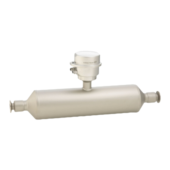
Combines in-line viscosity and flow measurement with an ultra-compact
transmitter
Application
• Measuring principle operates independently of physical fluid
properties such as viscosity or density
• Measuring liquids and gases in applications requiring low
pressure loss and gentle fluid treatment
Device properties
• Straight, easy cleanable single-tube system
• TMB
®
technology
• Measuring tube made of Titanium
• Robust, ultra-compact transmitter housing
• High ingress protection: IP69K
• Local display available
Products
Technical Information
Proline Promass I 100
Coriolis flowmeter
Solutions
Your benefits
• Energy-saving – minimum pressure loss thanks to full-bore
design
• Fewer process measuring points – multivariable
measurement (flow, density, temperature)
• Space-saving installation – no in/outlet run needs
• Space-saving transmitter – full functionality on smallest
footprint
• Time-saving local operation without additional software and
hardware – integrated web server
• Integrated verification – Heartbeat Technology™
Services
Advertisement
Table of Contents

Related Manuals for Endress+Hauser Proline Promass I 100


Summary of Contents for Endress+Hauser Proline Promass I 100
- Page 1 Products Solutions Services TI01035D/06/EN/04.14 71254118 Technical Information Proline Promass I 100 Coriolis flowmeter Combines in-line viscosity and flow measurement with an ultra-compact transmitter Application Your benefits • Measuring principle operates independently of physical fluid • Energy-saving – minimum pressure loss thanks to full-bore...
-
Page 2: Table Of Contents
Proline Promass I 100 Table of contents Document information ..... . . 4 Shock resistance ......44 Vibration resistance . - Page 3 Proline Promass I 100 Registered trademarks ..... . 84 Endress+Hauser...
-
Page 4: Document Information
Proline Promass I 100 Document information Symbols used Electrical symbols Symbol Meaning Direct current A terminal to which DC voltage is applied or through which direct current flows. Alternating current A terminal to which alternating voltage is applied or through which alternating current flows. -
Page 5: Function And System Design
Proline Promass I 100 Symbol Meaning Hazardous area Indicates a hazardous area. Safe area (non-hazardous area) Indicates the non-hazardous area. Function and system design Measuring principle The measuring principle is based on the controlled generation of Coriolis forces. These forces are always present in a system when both translational and rotational movements are superimposed. -
Page 6: Measuring System
Proline Promass I 100 Measuring system The device consists of a transmitter and a sensor. If a device with Modbus RS485 intrinsically safe is ordered, the Safety Barrier Promass 100 is part of the scope of supply and must be implemented to operate the device. -
Page 7: Device Architecture
Proline Promass I 100 Device architecture A0016779 Possibilities for integrating measuring devices into a system Control system (e.g. PLC) EtherNet/IP PROFIBUS DP Modbus RS485 4-20 mA HART, pulse/frequency/switch output Safety Barrier Promass 100 Modbus RS485 intrinsically safe Non-hazardous area Non-hazardous area and Zone 2/Div. 2 Intrinsically safe area and Zone 1/Div. -
Page 8: Measuring Range
Proline Promass I 100 Measuring range Measuring ranges for liquids Measuring range full scale values to min(F) max(F) [mm] [in] [kg/h] [lb/min] ³⁄₈ 0 to 2 000 0 to 73.50 ½ 0 to 6 500 0 to 238.9 15 FB ½... -
Page 9: Operable Flow Range
Proline Promass I 100 Maximum possible full scale value: = · ρ : x = 70 000 kg/h · 60.3 kg/m³ : 90 kg/m³ = 46 900 kg/h max(G) max(F) Recommended measuring range "Flow limit" section (→ 48) Operable flow range Over 1000 : 1. -
Page 10: Signal On Alarm
Proline Promass I 100 Assignable measured • Mass flow variables • Volume flow • Corrected volume flow • Density • Reference density • Temperature The range of options increases if the measuring device has one or more application packages. Switch output... - Page 11 Proline Promass I 100 Current output 4-20 mA Failure mode Selectable (as per NAMUR recommendation NE 43): • Minimum value: 3.6 mA • Maximum value: 22 mA • Defined value: 3.59 to 22.5 mA • Actual value • Last valid value...
- Page 12 Proline Promass I 100 Operating tool • Via digital communication: – HART protocol – PROFIBUS DP – Modbus RS485 – EtherNet/IP • Via service interface Plain text display With information on cause and remedial measures Additional information on remote operation (→ 74)
-
Page 13: Galvanic Isolation
Proline Promass I 100 Transmitter Intrinsically safe values Order code for Terminal numbers "Approvals" Supply voltage Signal transmission 20 (L-) 10 (L+) 62 (A) 72 (B) • Option BM: ATEX II2G + IECEx Z1 Ex ia, II2D Ex tb = 16.24 V •... - Page 14 Proline Promass I 100 Dynamic variables Read out the dynamic variables: HART command 3 The measured variables can be freely assigned to the dynamic variables. Measured variables for PV (primary dynamic variable) • Mass flow • Volume flow • Corrected volume flow •...
- Page 15 Proline Promass I 100 Output values Analog input 1 to 8 (from measuring device to • Mass flow automation system) • Volume flow • Corrected volume flow • Target mass flow • Carrier mass flow • Density • Reference density •...
- Page 16 Proline Promass I 100 Broadcast address range Function codes • 03: Read holding register • 04: Read input register • 06: Write single registers • 08: Diagnostics • 16: Write multiple registers • 23: Read/write multiple registers Broadcast messages Supported by the following function codes: •...
- Page 17 Proline Promass I 100 Fix Input 5 ms to 10 s (factory setting: 20 ms) Exclusive Owner Multicast Instance Size [byte] Instance configuration: 0x68 O → T configuration: 0x66 T → O configuration: 0x64 Exclusive Owner Multicast Instance Size [byte]...
- Page 18 Proline Promass I 100 Configurable Input Assembly • Current device diagnostics • Mass flow • Volume flow • Corrected volume flow • Density • Reference density • Temperature • Totalizer 1 • Totalizer 2 • Totalizer 3 The range of options increases if the measuring device has one or more application packages.
-
Page 19: Power Supply
Proline Promass I 100 Power supply Terminal assignment Overview: housing version 1.1 1.2 1.3 2.1 2.2 A0016770 Housing version: compact, aluminum coated Housing version: compact, hygienic, stainless Housing version: ultra compact, hygienic, stainless, M12 device plug Connection version: 4-20 mA HART, pulse/frequency/switch output 1.1 Signal transmission: pulse/frequency/switch output... - Page 20 Proline Promass I 100 Depending on the housing version, the transmitters can be ordered with terminals or device plugs. Connection methods available Order code for Possible options for order code Power "Housing" "Electrical connection" Outputs supply Options Terminals Terminals • Option A: coupling M20x1 A, B •...
- Page 21 Proline Promass I 100 PROFIBUS DP connection version For use in the non-hazardous area and Zone 2/Div. 2. Order code for "Output", option L Depending on the housing version, the transmitters can be ordered with terminals or device plugs. Connection methods available...
- Page 22 Proline Promass I 100 Modbus RS485 connection version For use in the non-hazardous area and Zone 2/Div. 2. Order code for "Output", option M Depending on the housing version, the transmitters can be ordered with terminals or device plugs. Connection methods available...
- Page 23 Proline Promass I 100 Modbus RS485 connection version For use in the intrinsically safe area. Connection via Safety Barrier Promass 100. Order code for "Output", option M Depending on the housing version, the transmitters can be ordered with terminals or device plugs.
- Page 24 Proline Promass I 100 EtherNet/IP connection version Order code for "Output", option N Depending on the housing version, the transmitters can be ordered with terminals or device plugs. Connection methods available Order code for Possible options for order code Power "Housing"...
-
Page 25: Pin Assignment, Device Plug
Proline Promass I 100 Safety Barrier Promass 100 Power Modbus supply RS485 Safe area Power Lift panel for bus termination Communication Safety Barrier Promass 100 Hazardous area Power Modbus supply RS485 A0016922 Safety Barrier Promass 100 with terminals Non-hazardous area and Zone 2/Div. 2... - Page 26 Proline Promass I 100 4-20 mA HART with pulse/frequency/switch output Device plug for signal transmission (device side) Assignment Coding Plug/socket 4-20 mA HART (active) Socket 4-20 mA HART (active) Pulse/frequency/switch output (passive) Pulse/frequency/switch output (passive) A0016810 Grounding/shielding • Recommended plug: Binder, series 763, part no. 79 3439 12 05 •...
-
Page 27: Power Consumption
Proline Promass I 100 Device plug for signal transmission (device side), MODBUS RS485 (not intrinsically safe) For use in the non-hazardous area and Zone 2/Div. 2. Assignment Coding Plug/socket Socket Modbus RS485 Modbus RS485 Grounding/shielding A0016811 • Recommended plug: Binder, series 763, part no. 79 4449 20 05 •... -
Page 28: Current Consumption
Proline Promass I 100 Safety Barrier Promass 100 Order code for Maximum "Output" Power consumption Option M: Modbus RS485, for use in intrinsically safe areas 4.8 W Current consumption Transmitter Order code for Maximum Maximum "Output" Current consumption switch-on current Option B: 4-20mA HART, pul./... - Page 29 Proline Promass I 100 Connection examples Current output 4-20 mA HART 4...20 mA – A0016800 Connection example for 4-20 mA HART current output (active) Automation system with current input (e.g. PLC) Cable shield, observe cable specifications (→ Connection for HART operating devices (→...
- Page 30 Proline Promass I 100 PROFIBUS DP A0021429 Connection example for PROFIBUS DP, non-hazardous area and Zone 2/Div. 2 Control system (e.g. PLC) Cable shield: the cable shield must be grounded at both ends to comply with EMC requirements; observe cable specifications (→...
- Page 31 Proline Promass I 100 L- L+ A0016804 Connection example for Modbus RS485 intrinsically safe Control system (e.g. PLC) Cable shield, observe cable specifications (→ Safety Barrier Promass 100 Observe cable specifications (→ Non-hazardous area Non-hazardous area and Zone 2/Div. 2...
-
Page 32: Potential Equalization
Proline Promass I 100 HART input 4...20 mA A0019828 Connection example for HART input (burst mode) via current output (active) Cable shield, observe cable specifications (→ Resistor for HART communication (≥ 250 Ω): observe maximum load (→ Connection for HART operating devices (→... -
Page 33: Cable Entries
Proline Promass I 100 Cable entries • Cable gland: M20 × 1.5 with cable 6 to 12 mm (0.24 to 0.47 in) • Thread for cable entry: – NPT ½" – G ½" – M20 Cable specification Permitted temperature range •... -
Page 34: Performance Characteristics
Proline Promass I 100 For more information on planning and installing EtherNet/IP networks, please refer to the "Media Planning and Installation Manual. EtherNet/IP" of the ODVA Organization. Connecting cable between Safety Barrier Promass 100 and measuring device Cable type Shielded twisted-pair cable with 2x2 wires. When grounding the cable shield, observe the grounding concept of the plant. - Page 35 Proline Promass I 100 Zero point stability Zero point stability [mm] [in] [kg/h] [lb/min] ³⁄₈ 0.150 0.0055 ½ 0.488 0.0179 15 FB ½ FB 1.350 0.0496 1.350 0.0496 25 FB 1 FB 3.375 0.124 1½ 3.375 0.124 40 FB 1 ½ FB 5.25...
-
Page 36: Repeatability
Proline Promass I 100 1:10 1:20 1:50 1:100 1:500 [inch] [lb/min] [lb/min] [lb/min] [lb/min] [lb/min] [lb/min] 2 573 257.3 128.7 51.46 25.73 5.146 2 FB 6 615 661.5 330.8 132.3 66.15 13.23 6 615 661.5 330.8 132.3 66.15 13.23 FB = Full bore Accuracy of outputs o.r. -
Page 37: Influence Of Medium Pressure
Proline Promass I 100 Wide-range density specification (special density calibration) If the process temperature is outside the valid range (→ 34) the measured error is ±0.0001 g/cm /°C (±0.00005 g/cm /°F) [kg/m ] [°C] [°F] -40 0 40 80 120 160 200 240 280 320 A0016614 Field density calibration, for example at +20 °C (+68 °F) -
Page 38: Installation
Proline Promass I 100 Calculation of the maximum measured error as a function of the flow rate Flow rate Maximum measured error in % o.r. ZeroPoint ⋅ ± BaseAccu ³ BaseAccu A0021339 A0021332 ZeroPoint ZeroPoint ⋅ ⋅ ± < MeasValue... - Page 39 Proline Promass I 100 A0023344 Installation in down pipes However, the following installation suggestion allows for installation in an open vertical pipeline. Pipe restrictions or the use of an orifice with a smaller cross-section than the nominal diameter prevent the sensor running empty while measurement is in progress.
-
Page 40: Orientation
Proline Promass I 100 Orientation The direction of the arrow on the sensor nameplate helps you to install the sensor according to the flow direction (direction of medium flow through the piping). Orientation Recommendation Vertical orientation A0015591 Horizontal orientation, transmitter... - Page 41 Proline Promass I 100 Securing with mounting clamp in the case of hygiene connections It is not necessary to provide additional support for the sensor for operational performance purposes. If, however, additional support is required for installation purposes, the following dimensions must be observed.
-
Page 42: Mounting Safety Barrier Promass 100
‣ If operating outdoors: Avoid direct sunlight, particularly in warm climatic regions. Weather protection covers can be ordered from Endress+Hauser: see "Accessories" section Temperature tables In the following tables, the following interdependencies between the maximum medium temperature for T1-T6 and the maximum ambient temperature T apply when operating the device in hazardous areas. - Page 43 Proline Promass I 100 Order code for "Housing" [°C] [85 °C] [100 °C] [135 °C] [200 °C] [300 °C] [450 °C] – – – The following applies for specified sensors with a maximum medium temperature T = 200 °C: T = 170 °C...
-
Page 44: Ambient Temperature Range
Proline Promass I 100 Explosion hazards arising from gas and dust Determining the temperature class and surface temperature with the temperature table • In the case of gas: Determine the temperature class as a function of the ambient temperature T and the medium temperature T •... -
Page 45: Electromagnetic Compatibility (Emc)
Proline Promass I 100 Electromagnetic • As per IEC/EN 61326 and NAMUR Recommendation 21 (NE 21) compatibility (EMC) • Complies with emission limits for industry as per EN 55011 (Class A) • Device version with PROFIBUS DP: Complies with emission limits for industry as per EN 50170 Volume 2, IEC 61784 The following applies for PROFIBUS DP: If baud rates >... - Page 46 Proline Promass I 100 Flange connection according to ASME B16.5 [psi] [bar] 1200 Class 600 1000 Class 300 Class 150 [°C] [°F] A0020923-EN With flange material 1.4301 (304); wetted parts: titanium Flange connection according to JIS B2220 [psi] [bar] 1000 [°C]...
- Page 47 Proline Promass I 100 Process connection to DIN 11851 [psi] [bar] DN 8…40 DN 50…80 [°C] [°F] A0021004-EN With titanium connection material DIN 11851 allows for applications up to +140 °C (+284 °F) if suitable sealing materials are used. Please take this into account when selecting seals and counterparts, as these components can limit the pressure and temperature range.
-
Page 48: Secondary Containment Pressure Rating
Proline Promass I 100 Threaded hygienic connection to ISO 2853 [psi] [bar] [°C] [°F] A0020919-EN With titanium connection material Tri-Clamp The clamp connections are suitable up to a maximum pressure of 16 bar (232 psi). Please observe the operating limits of the clamp and seal used as they could be under 16 bar (232 psi). The clamp and seal are not included in the scope of supply. -
Page 49: Pressure Loss
Proline Promass I 100 For an overview of the measuring range full scale values, see the "Measuring range" section (→ 8) • The minimum recommended full scale value is approx. 1/20 of the maximum full scale value • In most applications, 20 to 50 % of the maximum full scale value can be considered ideal •... -
Page 50: Heating
Some fluids require suitable measures to avoid loss of heat at the sensor. Heating options • Electrical heating, e.g. with electric band heaters • Via pipes carrying hot water or steam • Via heating jackets Heating jackets for the sensor can be ordered as accessories from Endress+Hauser (→ 81). Endress+Hauser... -
Page 51: Vibrations
Proline Promass I 100 Vibrations The high oscillation frequency of the measuring tubes ensures that the correct operation of the measuring system is not influenced by plant vibrations. Endress+Hauser... -
Page 52: Mechanical Construction
Proline Promass I 100 Mechanical construction Design, dimensions Compact version Order code for "Housing", option A "Compact coated alu" A0016456 Dimensions SI units 1) 2) 1) 2) [mm] [mm] [mm] [mm] [mm] [mm] [mm] [mm] [mm] 147.5 93.5 207.2 264.4 8.55... - Page 53 Proline Promass I 100 1) 2) [in] [in] [in] [in] [in] [in] [in] [in] [in] 5.35 5.81 3.68 2.13 10.1 13.42 1.40 5.35 5.81 3.68 2.13 10.1 14.42 2.16 5.35 5.81 3.68 2.13 10.1 14.42 2.16 FB = Full bore If using an extension neck for the extended temperature range, order code for "Sensor option", option CG:...
- Page 54 Proline Promass I 100 Dimensions US units 1) 2) [in] [in] [in] [in] [in] [in] [in] [in] [in] ³⁄₈ 5.26 5.39 3.07 2.31 7.96 10.41 0.34 ¹⁄ 5.26 5.39 3.07 2.31 7.96 10.41 0.45 ¹⁄ FB 5.26 5.39 3.07 2.31 7.96...
- Page 55 Proline Promass I 100 1) 2) [mm] [mm] [mm] [mm] [mm] [mm] [mm] [mm] [mm] 111.4 123.6 67.7 55.9 251.6 366.2 54.76 FB = Full bore If using an extension neck for the extended temperature range, order code for "Sensor option", option CG: values +70 mm If using a display, order code for "Display;...
- Page 56 Proline Promass I 100 Flange according to EN 1092-1 (DIN 2501 ), PN 40: 1.4301 (304), wetted parts: titanium (order code for "Process connection", option D2W) Surface roughness (flange): EN 1092-1 Form B1 (DIN 2526 Form C), Ra 3.2 to 12.5 µm...
- Page 57 Proline Promass I 100 Flange connections ASME B16.5 100 (4") 125 (5") ≤ ≥ +1.5 (+0.06) ±3.5 (±0.14) −2.0 (–0.08) A0015621 Engineering unit mm (in) Flange according to ASME B16.5, Cl 150: 1.4301 (304), wetted parts: titanium (order code for "Process connection", option AAW)
- Page 58 Proline Promass I 100 Flange according to ASME B16.5, Cl 300: 1.4301 (304), wetted parts: titanium (order code for "Process connection", option ABW) Surface roughness (flange): Ra 3.2 to 6.3 µm [mm] [mm] [mm] [mm] [mm] [mm] [mm] 127.0 8 × Ø19.1 52.60...
- Page 59 Proline Promass I 100 Flange JIS B2220, 10K: 1.4301 (304), wetted parts: titanium (order code for "Process connection", option NDW) Surface roughness (flange): Ra 3.2 to 6.3 µm [mm] [mm] [mm] [mm] [mm] [mm] [mm] 4 × Ø19 50 FB 4 ×...
- Page 60 Proline Promass I 100 Flange JIS B2220, 63K: 1.4301 (304), wetted parts: titanium (order code for "Process connection", option NHW) Surface roughness (flange): Ra 3.2 to 6.3 µm [mm] [mm] [mm] [mm] [mm] [mm] [mm] 4 × Ø19 12.00 4 × Ø19 12.80...
- Page 61 Proline Promass I 100 1", 1½", 2" -Tri-Clamp for pipe size: titanium (order code for "Process connection", option FTW) Clamp [mm] [in] [mm] [mm] [mm] 90.9 72.9 1 268 3A version available (order code for "Additional approval", option LP) in combination with Ra ≤ 0.8 µm, Ra ≤...
- Page 62 Proline Promass I 100 Eccentric Tri-Clamp: Titanium Order code for Clamp [mm] "Process connection", [in] [mm] [mm] [mm] Option 15 FB 50.5 22.1 50.5 22.1 25 FB 1½ 50.5 34.8 1½ 50.5 34.8 40 FB 47.5 47.5 50 FB 2 ½...
- Page 63 Proline Promass I 100 Threaded hygienic connection (sanitary connection) DIN 11851: titanium (order code for "Process connection", option KCW) [mm] [in] [mm] [mm] Rd 110 × 1/4 1 268 3A version available (order code for "Additional approval", option LP) in combination with Ra ≤ 0.8 µm (order code for "Measuring tube material", option CB)
- Page 64 Proline Promass I 100 Threaded hygienic connection DIN 11864-1 Form A: titanium (order code for "Process connection", option KEW) [mm] [in] [mm] [mm] Rd 110 × 1/4 1 268 3A version available (order code for "Additional approval", option LP) in combination with Ra ≤ 0.8 µm, Ra ≤...
- Page 65 Proline Promass I 100 ISO 2853 (threaded hygienic connection) +1,5 (+0.06) -2,0 (-0.08) A0015623 Engineering unit mm (in) Threaded hygienic connection ISO 2853: titanium (order code for "Process connection", option JSE) [mm] [mm] [mm] [mm] 37.13 22.6 37.13 22.6 15 FB 37.13...
- Page 66 Proline Promass I 100 Threaded hygienic connection SMS 1145: titanium (order code for "Process connection", option SCS) [mm] [in] [mm] [mm] Rd 40 × 1/6 22.5 Rd 40 × 1/6 22.5 Rd 40 × 1/6 22.5 25 FB Rd 40 × 1/6 22.5...
- Page 67 Proline Promass I 100 Flange according to ASME B16.5, Cl 150: 1.4301 (304), wetted parts: titanium (order code for "Process connection", option AAW) Surface roughness (flange): Ra 3.2 to 6.3 µm [in] [in] [in] [in] [in] [in] [in] 7.48 6.00 4 ×...
- Page 68 Proline Promass I 100 Tri-Clamp +1,5 (+0.06) -2,0 (-0.08) A0015625 Engineering unit mm (in) 1", 1½", 2" -Tri-Clamp for pipe size: titanium (order code for "Process connection", option FTW) Clamp [in] [in] [in] [in] [in] ³⁄₈ 1.98 0.87 16.81 ¹⁄...
- Page 69 Proline Promass I 100 ½" Tri-Clamp: titanium (order code for "Process connection", option FBW) Clamp [in] [in] [in] [in] [in] ³⁄₈ ½ 0.98 0.37 16.77 ¹⁄ ½ 0.98 0.37 18.19 3A version available (order code for "Additional approval", option LP) in combination with Ra ≤ 32 µin Ra ≤...
- Page 70 Proline Promass I 100 SMS 1145 (threaded hygienic connection) +1,5 (+0.06) -2,0 (-0.08) A0015628 Engineering unit mm (in) Threaded hygienic connection SMS 1145: titanium (order code for "Process connection", option SCS) [in] [in] [in] [in] ³⁄₈ Rd 40 × 1/6 0.89...
-
Page 71: Weight
Proline Promass I 100 [mm] [in] [mm] [in] [mm] [in] [mm] [in] 4.25 114.5 4.51 22.5 0.89 Accessories Purge connections / secondary containment monitoring Order code for "Sensor options", option CH A0003321 [mm] [in] [in] [mm] [in] [mm] [in] ³⁄₈... -
Page 72: Materials
Proline Promass I 100 Weight [kg] [mm] FB = Full bore Weight in US units All values (weight) refer to devices with EN/DIN PN 40 flanges. Weight information in [lbs]. Weight [lbs] [in] ½ ½ FB 1 FB 1½ 1½ FB... - Page 73 Proline Promass I 100 Order code for "Housing", option A "Compact, coated aluminum" The various cable entries are suitable for hazardous and non-hazardous areas. Cable entry/cable gland Material Cable gland M20 × 1.5 Nickel-plated brass Adapter for cable entry with internal thread G ½"...
-
Page 74: Process Connections
Proline Promass I 100 Process connections • Flanges: – EN 1092-1 (DIN 2501) – EN 1092-1 (DIN 2512N) – ASME B16.5 – JIS B2220 • Tri-Clamp (OD tubes) • Clamp (eccentric) : Tri-Clamp • Threaded hygienic connection: – DIN 11851 –... - Page 75 Proline Promass I 100 A0016948 Options for remote operation via HART protocol Control system (e.g. PLC) Field Communicator 475 Computer with operating tool (e.g. FieldCare, AMS Device Manager, SIMATIC PDM) Commubox FXA195 (USB) Field Xpert SFX350 or SFX370 VIATOR Bluetooth modem with connecting cable...
-
Page 76: Service Interface
Proline Promass I 100 A0020903 Automation system Computer with PROFIBUS network card PROFIBUS DP network Measuring device Service interface Service interface (CDI-RJ45) This communication interface is present in the following device version: • Order code for "Output", option B: 4-20 mA HART, pulse/frequency/switch output •... - Page 77 Proline Promass I 100 PROFIBUS DP A0021270 Connection for order code for "Output", option L: PROFIBUS DP Service interface (CDI -RJ45) of the measuring device with access to the integrated Web server Computer with Web browser (e.g. Internet Explorer) for accessing the integrated device Web server or with "FieldCare"...
-
Page 78: Certificates And Approvals
Directives. These are listed in the corresponding EC Declaration of Conformity along with the standards applied. Endress+Hauser confirms successful testing of the device by affixing to it the CE mark. C-Tick symbol The measuring system meets the EMC requirements of the "Australian Communications and Media Authority (ACMA)". -
Page 79: Hygienic Compatibility
For devices with nominal diameters less than or equal to DN 25 (1"), this is neither possible nor necessary. • With the PED/G1/x (x = category) marking on the sensor nameplate, Endress+Hauser confirms compliance with the "Essential Safety Requirements" specified in Annex I of the Pressure Equipment Directive 97/23/EC. -
Page 80: Ordering Information
The application packages can be ordered from Endress+Hauser either directly with the device or subsequently. Detailed information on the order code in question is available from your local Endress +Hauser sales center or on the product page of the Endress+Hauser website: www.endress.com. -
Page 81: Concentration
Accessories Various accessories, which can be ordered with the device or subsequently from Endress+Hauser, are available for the device. Detailed information on the order code in question is available from your local Endress+Hauser sales center or on the product page of the Endress+Hauser website: www.endress.com. -
Page 82: Service-Specific Accessories
The application already contains the data of your Endress+Hauser device. Endress +Hauser also takes care of maintaining and updating the data records. -
Page 83: System Components
• The W@M Device Viewer : Enter the serial number from the nameplate (www.endress.com/deviceviewer) • The Endress+Hauser Operations App: Enter the serial number from the nameplate or scan the 2-D matrix code (QR code) on the nameplate. Standard documentation... - Page 84 Registered trademark of the Microsoft Corporation, Redmond, Washington, USA TRI-CLAMP ® Registered trademark of Ladish & Co., Inc., Kenosha, USA Applicator , FieldCare , Field Xpert , HistoROM , TMB , Heartbeat Technology ® ® ® ® Registered or registration-pending trademarks of the Endress+Hauser Group www.addresses.endress.com...