Advertisement
Quick Links
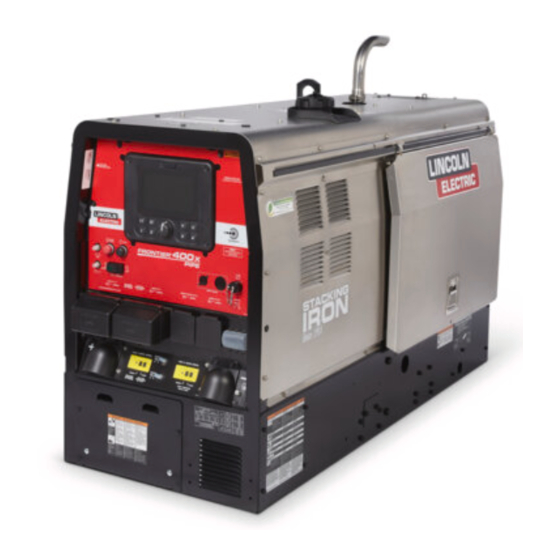
Operator's Manual
Frontier
Register your machine:
www.lincolnelectric.com/register
Authorized Service and Distributor Locator:
www.lincolnelectric.com/locator
Save for future reference
Date Purchased
Code: (ex: 10859)
Serial: (ex: U1060512345)
IM10605
| Issue Date Jul - 22
© Lincoln Global, Inc. All Rights Reserved.
400X /Frontier 400X Pipe
®
®
For use with machines having Code Numbers:
12716, 12717, 12781,
13202
Need Help? Call 1.888.935.3877
to talk to a Service Representative
Hours of Operation:
8:00 AM to 6:00 PM (ET) Mon. thru Fri.
After hours?
Use "Ask the Experts" at lincolnelectric.com
A Lincoln Service Representative will contact you
no later than the following business day.
For Service outside the USA:
Email: globalservice@lincolnelectric.com
Advertisement

Related Manuals for Lincoln Electric Frontier 400X


Summary of Contents for Lincoln Electric Frontier 400X
- Page 1 Operator’s Manual Frontier 400X /Frontier 400X Pipe ® ® For use with machines having Code Numbers: 12716, 12717, 12781, 13202 Need Help? Call 1.888.935.3877 Register your machine: to talk to a Service Representative www.lincolnelectric.com/register Authorized Service and Distributor Locator: Hours of Operation: www.lincolnelectric.com/locator...
- Page 2 THANK YOU FOR SELECTING KEEP YOUR HEAD OUT OF THE FUMES. A QUALITY PRODUCT BY DON’T get too close to the arc. LINCOLN ELEC TRIC. Use corrective lenses if necessary to stay a reasonable distance away from the arc. READ and obey the Safety Data PLEASE EXAMINE CARTON AND EQUIPMENT FOR Sheet (SDS) and the warning label DAMAGE IMMEDIATELY...
- Page 3 P.O. Box 351040, Miami, Florida 33135 or CSA Standard W117.2. A Free copy of “Arc Welding Safety” booklet E205 2.a. Electric current flowing through any conductor is available from the Lincoln Electric Company, 22801 causes localized Electric and Magnetic Fields (EMF). St. Clair Avenue, Cleveland, Ohio 44117-1199.
- Page 4 SAFETY ELECTRIC SHOCK ARC RAYS CAN BURN. CAN KILL. 3.a. The electrode and work (or ground) circuits are 4.a. Use a shield with the proper filter and cover plates to protect your electrically “hot” when the welder is on. Do eyes from sparks and the rays of the arc when welding or not touch these “hot”...
- Page 5 SAFETY WELDING AND CUTTING CYLINDER MAY EXPLODE IF SPARKS CAN CAUSE DAMAGED. FIRE OR EXPLOSION. 7.a. Use only compressed gas cylinders containing the correct shielding gas for the process used 6.a. Remove fire hazards from the welding area. If and properly operating regulators designed for this is not possible, cover them to prevent the welding sparks the gas and pressure used.
- Page 6 TABLE OF CONTENTS...
- Page 7 TABLE OF CONTENTS ACCESSORIES ..............................SECTION C MAINTENANCE .............................SECTION D TROUBLESHOOTING............................SECTION E WIRING, CONNECTION DIAGRAMS AND DIMENSION PRINT ................SECTION F PARTS LIST .......................PARTS.LINCOLNELECTRIC.COM...
- Page 8 FRONTIER 400X ® GRAPHIC SYMBOLS – DigFX™...
- Page 9 FRONTIER 400X ® GRAPHIC SYMBOLS The following graphics appear on the Frontier or in the manual. Stop Start Glow Plug Receptacle Electrode Type Diameter Material Thickness Productivity Metrics Arc Hours Auxiliary Hours Utilization Rate Standby Hours Fuel Savings...
- Page 10 Pipe (SMAW)** 30-400 Amps The machine has been equipped with Crosslinc® Technology **Only available on Frontier 400X Pipe model to provide weld cable communication for voltage control at the Open Circuit Voltage arc without the need for a control cable.
- Page 11 FRONTIER 400X INSTALLATION ® INSTALLATION SAFETY PRECAUTIONS WARNING Do not attempt to use this equipment until you have thoroughly read all operating and maintenance manuals supplied with your machine. They include important safety precautions, detailed engine starting, operating and maintenance instructions and parts lists. ELECTRIC SHOCK can kill.
- Page 12 INSTALLATION FRONTIER ® 400X STORING HIGH ALTITUDE OPERATION 1. Store the machine in a cool, dry place when it is not in use. At higher altitudes, output derating may be necessary. Protect it from dust and dirt. Keep it where it can’t be Perkins: For maximum rating, derate the welder output 2% for accidentally damaged from construction activities, moving every 1000 ft.
- Page 13 INSTALLATION FRONTIER ® 400X WARNING TOWING Use a recommended trailer for use with this equipment for road, • Stop engine and allow to cool before fueling. in-plant and yard towing by a vehicle . If the user adapts a non- •...
- Page 14 INSTALLATION FRONTIER ® 400X BATTERY CONNECTION SPARK ARRESTOR CAUTION Some federal, state or local laws may require that gasoline or diesel engines be equipped with exhaust spark arrestors when they are operated in certain locations where unarrested sparks Use caution as the electrolyte is a strong acid that can burn skin and damage eyes.
- Page 15 INSTALLATION FRONTIER ® 400X MACHINE GROUNDING The 120 VAC auxiliary power receptacles should only be used with three wire grounded type plugs or approved double insulated tools Because this portable engine driven welder creates its own power, with two wire plugs. The current rating of any plug used with the it is not necessary to connect its frame to an earth ground, unless system must be at least equal to the current capacity of the the machine is connected to premises wiring (home, shop, etc.).
- Page 16 FRONTIER 400X INSTALLATION ® STANDBY POWER CONNECTIONS 2. Take necessary steps to assure load is limited to the capacity ® of the Frontier 400X by installing a 50 amp, 240 VAC double ® The Frontier 400X is suitable for temporary, standby or pole circuit breaker.
- Page 17 INSTALLATION FRONTIER ® 400X CAUTION WELDING OUTPUT CABLES • Loose connections will cause the output terminals to With the engine off, connect to the terminals provided. These overheat. The terminals may eventually melt. connections should be checked periodically and tightened if •...
- Page 18 INSTALLATION FRONTIER ® 400X CABLE INDUCTANCE AND ITS EFFECTS ON CROSSLINC TECHNOLOGY WELDING This machine features CrossLinc technology, which allows for Excessive cable inductance will cause the welding performance remote control of the welding output via the weld cables rather to degrade.
- Page 19 INSTALLATION FRONTIER ® 400X For electrode negative, connect the electrode cable “-” terminal of the welder and work cable to the “+” terminal of ACCESSORY CONNECTION DIAGRAMS the welder. Installation diagrams for common setups are WARNING included on the following pages. Shut off welder before making or removing any electrical connections.
- Page 20 FRONTIER 400X INSTALLATION ® CROSSLINC REMOTE SETUP EXAMPLE FIGURE A.9 Description Product Number QTY Frontier ® 400X Welder/ K3484-1 Generator ® CrossLinc Remote K4345-1 EH-305D Electrode K909-7 Holder Electrode Cable - 2/0, 50 K2485-2 ft. (15.3 m), Black Electrode Cable - 2/0, 10 K2483-2 ft.
- Page 21 INSTALLATION FRONTIER ® 400X TIG SETUP WITH FOOT PEDAL EXAMPLE Description Product Number QTY FIGURE A.12 Frontier 400X Welder/ ® K3484-1 Generator PTA-26V TIG Torch - 25 ft. K1783-9 (7.6 m) Foot Pedal K870-2 Gas Regulator and Hose K586-1 Electrode Cable - 2/0, 50 K2485-2 ft.
- Page 22 Many variables beyond the control of The Lincoln Electric Company affect the results obtained in applying these programs. These variables include, but are not limited to, welding procedure, plate chemistry and temperature, weldment design, fabrication methods and service requirements.
- Page 23 FRONTIER 400X OPERATION ® STARTING THE ENGINE ADDING FUEL WARNING engine before starting if needed. Then, press and hold the START button until the machine turns over. • Stop engine while fueling. Release the engine START button immediately when the •...
- Page 24 FRONTIER 400X OPERATION ® TYPICAL FUEL CONSUMPTION (CONT) (Kubota D1503-M) Fuel Consumption RUN TIME (HRS.) GAL. / HR. L / HR. WITH FULL TANK* 0.43 1.63 46.39 Low Idle, no load 0.29 1.09 69.58 0.58 2.21 34.29 0.80 3.01 25.17 1.12 4.26 17.79...
- Page 25 FRONTIER 400X OPERATION ® CONTROLS AND SETTINGS All welder and engine controls are located on the case front panel. Refer to Figure B.1 and the explanations that follow. • When the electrode touches the work or power is drawn SYSTEM CONTROLS for lights or tools (approximately 100 watts minimum) the engine accelerates and operates at full speed.
- Page 26 FRONTIER 400X OPERATION ® SYSTEM CONTROLS CONT. 9. APEX® SYSTEM CONNECTORS - Optional connectors available via separate kit. Kit includes needed components to power an APEX® System. 10. 12-PIN CONNECTOR - Used for attaching optional remote control equipment. The K2909-1 (12-pin to 6-pin) adapter can be used for attaching to accessories requiring the 6-pin connector.
- Page 27 FRONTIER 400X OPERATION ® USER INTERFACE CONTROLS & NAGIVATION FIGURE B.2 1. KNOB AND PUSH BUTTON - Rotate the knob to 10. USB PORT - Conduct machine updates by inserting adjust values and move through the menus and push the a USB drive.
- Page 28 400X power source. The proper weld mode ® should be used based off desired application. Many variables beyond the control of The Lincoln Electric Company affect the results obtained in applying these programs. These variables include, but are not limited to, welding procedure, plate chemistry and temperature, weldment design, fabrication methods and service requirements.
- Page 29 ® FRONTIER 400X OPERATION Next to the engine indicators are weld setting and operation indicators. From top to bottom: After selecting the weld process, use the center knob to adjust the welding output (See Figure B.4). OFF. 6. WELDING MODE - Indicates the current welding mode of In constant current modes, the knob adjusts the welding the machine.
- Page 30 ® FRONTIER 400X OPERATION After striking an welding arc, the screen with change to the ACTIVE WELD SCREEN to show the real time amperage and amperage and voltage for approximately 5 seconds, and the UI will automatically return to the weld mode screen. This allows the operator to read the actual current and voltage just prior to when welding was ceased.
- Page 31 ® FRONTIER 400X OPERATION Within an active welding process, press the knob to view additional arc options. welding performance. The options available will depend on the weld mode selected. Welding settings are remembered between each weld mode. FIGURE B.6 Push knob to access the Weld Settings screen output range that can be controlled remotely.
- Page 32 FRONTIER 400X OPERATION ® WELD MODE SETTINGS CONT • Hot Start - Provides a temporary increase of the output current during the start of a weld. This helps ignite the arc quickly and reliably, preventing the electrode from sticking. The setting can be adjusted from 0 (Off) to +10.
- Page 33 FRONTIER 400X OPERATION ® NOTE: Touch Start mode avoids tungsten contamination WELD MODE SETTINGS CONT without the use of a high frequency unit. During the time the tungsten is touching the work, there is very little voltage or • Weld Terminal - Allows the operator to select if the current and, in general, this avoids tungsten contamination.
- Page 34 FRONTIER 400X OPERATION ® ENGINE STATUS SCREEN The Engine Status Screen provides information about the engine servicing and operation. In the MAIN MENU, use the knob to scroll and press to select the ENGINE SCREEN (See Figure B.11). If a yellow indicator is present, the machine has an active alert. B-13...
- Page 35 FRONTIER 400X OPERATION ® FIGURE B.14 ENGINE STATUS SCREEN CONT Within the screen, six engine parts are monitored for service: • Oil • Air Filter • Water Separator • Fuel FIlter • Engine Coolant • Alternator Belt FIGURE B.12 Also within the ENGINE STATUS SCREEN, the engine hours and RPMs can be found near the upper left-hand corner.
- Page 36 FRONTIER 400X OPERATION ® FIGURE B.18 The SETTINGS menu allows the operator to customize the machine to their preferences (See Figure B.17). FIGURE B.17 Inside the screen, the additional machine options listed below: • Display Units - Choose between Imperial and Metric units •...
- Page 37 FRONTIER 400X OPERATION ® MANAGING RESTRICTIONS number)! The PIN may only be reset by a Lincoln authorized service shop. The MANAGING RESTRICTIONS section of the settings menu may be used to restrict unauthorized access to the machine or operator access to the engine and settings menus. To enable restricti Operator PIN.
- Page 38 FRONTIER 400X OPERATION ® To restart the engine remotely, tap the stick electrode to the AUTO-STOP/START work piece: Stick Electrode fuel costs for users that do not weld continuously. When Auto- 1. Tap and hold a stick electrode to the work piece for 0.1 Stop/Start is enabled, the machine will automatically shut off to 1 second.
- Page 39 FRONTIER 400X OPERATION ® MEMORY MODE OPERATION PRODUCTIVITY METRICS FIGURE B.22 The machine features 4 global memories slots, which can be used to save and recall settings. The operator can use the MEMORY MODE under the WELD MODE settings or the four buttons labelled 1 –...
- Page 40 FRONTIER 400X OPERATION ® WELDER OPERATION TABLE B.2 CROSSLINC® TECHNOLOGY ELECTRODE CURRENT RANGE DIAMETER DCEP (+) This machine has been equipped with CrossLinc® Technology to 1/8" (3.2 mm) 30-60 Amps provide voltage and amperage control at the arc without the need 5/32"...
- Page 41 The current rating of any plug used with the system must be at **Only available on the Frontier 400X Pipe model** least equal to the current capacity of the associated receptacle. pipe welding applications to provide superior welding performance for cellulosic and low-hydrogen stick electrodes.
- Page 42 FRONTIER 400X OPERATION ® SIMULTANEOUS WELDING AND AUXILIARY POWER LOADS The auxiliary power capacity previously stated is maintained without any welding load. If a welding load is present, the available auxiliary power will decrease. The permissible currents shown assume that current is being drawn from either the 120 VAC or 240 VAC supply (not both at the same time).
- Page 43 FRONTIER 400X ACCESSORIES ® ACCESSORIES Full KVA Power Plug Kit CROSSLINC ACCESSORIES LN-25X Full KVA Adaptor power source, control cables are eliminated and voltage can be on engine-driven welders for portable power sources needing when using long welding power cables. Order: K4267-2 Activ8X APEX®...
- Page 44 FRONTIER 400X ACCESSORIES ® Arc Start Switch SERVICE KITS Engine Service Kits K3598-4 Perkins 403F-15T WIRE FEEDERS & GUNS K3599-5 Kubota D1503-M ® K126 Pro Innershield REMOTE CONTROLS ® Remote Output Control Connector Kit. Order: K126-12 connection to the welder. Order: CABLE ACCESSORIES ®...
- Page 45 FRONTIER 400X MAINTENANCE ® MAINTENANCE ROUTINE AND PERIODIC MAINTENANCE DAILY SAFETY PRECAUTIONS • Check the engine oil level. READ AND UNDERSTAND ENTIRE SECTION BEFORE OPERATING MACHINE. tank. • Open the water drain valve located on the bottom of the water WARNING separator element 1 or 2 turns and allow to drain into a container suitable for diesel fuel for 2 to 3 seconds.
- Page 46 FRONTIER 400X MAINTENANCE ® ENGINE MAINTENANCE Refer to the SERVICE PLAN section of the Engine Operator’s Manual for the recommended maintenance schedule of the following: a) Engine Oil and Filter b) Air Cleaner c) Fuel Filter and Delivery System d) Alternator Belt e) Battery f) Cooling System Refer to Table D.1 at the end of this section for various engine...
- Page 47 MAINTENANCE Service Instructions Service Instructions Single- and Two-Stage Engine Air Cleaners Single- and Two-Stage Engine Air Cleaners Inspect the New Filter for Damage Inspect the New Filter for Damage Remove the Filter Remove the Filter Inspect the new filter carefully, paying attention to Unfasten or unlatch the the inside of the open end, which is the service cover.
- Page 48 The coolant system is equipped with an internal expansion tank ------------------------------------------------------------------ located inside the top radiator tank. This allows for normal thermal ® The Frontier 400X expansion and contraction of the engine coolant. CHECKING AND REPLACING COOLANT / water separator and drain out any water daily. Close drain when WARNING diesel fuel starts to come out.
- Page 49 FRONTIER 400X MAINTENANCE ® BATTERY HANDLING ENGINE OIL CHANGE Drain the engine oil while the engine is warm to assure rapid and WARNING complete draining. It is recommended that each time the oil is GASES FROM BATTERY can explode. • Be sure the unit is off. Disconnect the negative battery cable to ensure safety.
- Page 50 FRONTIER 400X MAINTENANCE ® TIGHTENING THE FAN BELT If the fan belt is loose, the engine can overheat and the battery lose its charge. Check tightness by pressing on the belt midway between the pulleys. For tightness requirements, please refer to the Engine Owner's Manual.
- Page 51 FRONTIER 400X MAINTENANCE ® GFCI MODULE WARNING • An electric shock can result in serious injury or death. • Always perform the GFCI test before using the generator. If the GFCI system fails the test, the machine must be repaired by an authorized service center. •...
- Page 52 FRONTIER 400X TROUBLESHOOTING ® TROUBLESHOOTING HOW TO USE TROUBLESHOOTING GUIDE WARNING Service and Repair should only be performed by Lincoln Electric Factory Trained Personnel. Unauthorized repairs performed on this equipment may result in danger to the technician and machine operator and will invalidate your factory warranty.
- Page 53 FRONTIER 400X TROUBLESHOOTING ® Observe all Safety Guidelines detailed throughout this manual PROBLEMS POSSIBLE RECOMMENDED (SYMPTOMS) CAUSE COURSE OF ACTION ENGINE PROBLEMS Major Physical or Electrical Damage . Contact your Local Lincoln is Evident. Authorized Field Service Facility. Engine will not crank 1.
- Page 54 FRONTIER 400X TROUBLESHOOTING ® Observe all Safety Guidelines detailed throughout this manual PROBLEMS POSSIBLE RECOMMENDED (SYMPTOMS) CAUSE COURSE OF ACTION FUNCTION PROBLEMS Battery does not stay charged. 1. Faulty battery. 2. Faulty engine alternator. 3. Loose or broken lead in charging circuit.
- Page 55 FRONTIER 400X TROUBLESHOOTING ® Observe all Safety Guidelines detailed throughout this manual PROBLEMS POSSIBLE RECOMMENDED (SYMPTOMS) CAUSE COURSE OF ACTION FUNCTION PROBLEMS Engine goes to low idle but does 1. Faulty Idle Relay. not stay at low idle. 2. Intermittent Auxiliary load 3.
- Page 56 FRONTIER 400X WIRING DIAGRAMS ®...
- Page 57 FRONTIER 400X WIRING DIAGRAMS ®...
- Page 58 FRONTIER 400X DIMENSION PRINT ®...
- Page 62 Do not touch electrically live parts or Keep flammable materials away. Wear eye, ear and body protection. WARNING electrode with skin or wet clothing. Insulate yourself from work and ground. Spanish No toque las partes o los electrodos Mantenga el material combustible Protéjase los ojos, los oídos y el AVISO DE bajo carga con la piel o ropa moja-...
- Page 63 Keep your head out of fumes. Turn power off before servicing. Do not operate with panel open or Use ventilation or exhaust to guards off. WARNING remove fumes from breathing zone. Spanish Los humos fuera de la zona de res- Desconectar el cable de ali- No operar con panel abierto o AVISO DE...
- Page 64 Lincoln Electric is solely within the control of, and remains the sole responsibility of the customer. Many variables beyond the control of Lincoln Electric affect the results obtained in applying...