
Related Manuals for Lincoln Electric INVERTEC 400TPX


Summary of Contents for Lincoln Electric INVERTEC 400TPX
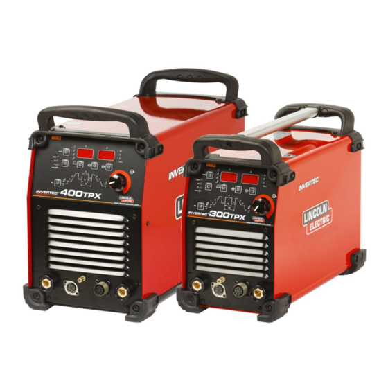
- Page 1 IM2041 09/2022 REV13 INVERTEC 300TPX & 400TPX OPERATOR’S MANUAL ENGLISH Lincoln Electric Bester Sp. z o.o. ul. Jana III Sobieskiego 19A, 58-260 Bielawa, Poland www.lincolnelectric.eu...
-
Page 2: Table Of Contents
12/05 THANKS! For having chosen the QUALITY of the Lincoln Electric products. Please Examine Package and Equipment for Damage. Claims for material damaged in shipment must be notified immediately to the dealer. For future reference record in the table below your equipment identification information. Model Name, Code & Serial Number can be found on the machine rating plate. -
Page 3: Technical Specifications
Technical Specifications NAME INDEX K12060-1 INVERTEC 300TPX CE K12060-2 INVERTEC 300TPX AUS K12060-6 INVERTEC 300TPX CCC K12043-1 INVERTEC 400TPX CE K12043-2 INVERTEC 400TPX AUS K12043-6 INVERTEC 400TPX CCC INPUT Input Voltage Input Power at Rated Output EMC Class Frequency 6.5kW @ 100% Duty Cycle (Stick) -
Page 4: Eco Design Information
ECO design information The equipment has been designed in order to be compliant with the Directive 2009/125/EC and the Regulation 2019/1784/EU. Efficiency and idle power consumption: Efficiency when max power consumption Index Name Equivalent model / Idle power consumption K12060-1 85,7% / 23W No equivalent model... - Page 5 Typical gas usage for MIG/MAG equipment: DC electrode positive Wire Wire Feeding Gas flow Material type diameter Shielding Gas Current Voltage [m/min] [l/min] [mm] Carbon, low 0,9 ÷ 1,1 95 ÷ 200 18 ÷ 22 3,5 – 6,5 Ar 75%, CO alloy steel Aluminium 0,8 ÷...
-
Page 6: Electromagnetic Compatibility (Emc)
If any electromagnetic disturbances are detected the operator must put in place corrective actions to eliminate these disturbances with, if necessary, assistance from Lincoln Electric. This equipment does not comply with IEC 61000-3-12. If it is connected to a public low-voltage system, it is responsibility of the installer or user of the equipment to ensure, by consultation with the distribution network operator if necessary, that the equipment may be connected. -
Page 7: Safety
Failure to follow the instructions in this manual could cause serious personal injury, loss of life, or damage to this equipment. Read and understand the following explanations of the warning symbols. Lincoln Electric is not responsible for damages caused by improper installation, improper care or abnormal operation. - Page 8 WELDING SPARKS CAN CAUSE FIRE OR EXPLOSION: Remove fire hazards from the welding area and have a fire extinguisher readily available. Welding sparks and hot materials from the welding process can easily go through small cracks and openings to adjacent areas. Do not weld on any tanks, drums, containers, or material until the proper steps have been taken to insure that no flammable or toxic vapors will be present.
-
Page 9: Installation And Operator Instructions
Installation and Operator Instructions Read this entire section before installation or operation of Output Connections the machine. A quick disconnect system using Twist-Mate cable plugs is used for the welding cable connections. Refer to Location and Environment the following sections for more information on connecting This machine will operate in harsh environments. - Page 10 TIG Welding (GTAW) Remote Control Connection This machine does not include a TIG torch necessary for Refer to the accessories section for a list of TIG welding, but one may be purchased separately. remote controls. If a remote control is used, Refer to the accessories section for more information.
- Page 11 Controls and Operational Features TIG mode: in Local and remote mode the output of the machine is OFF. A Trigger is necessary to enable Machine Start-Up: the output. When the machine is turned ON an auto-test is executed: during this test all the LEDs turn ON for a moment; at the same time the displays shown “333”...
- Page 12 Mode Pushbutton: Memory Pushbuttons: These pusbuttons allows to store (M) or recall (M) TIG welding programs. 9 memory records (P01 to P09) This pushbutton changes the welding modes of the are available for the user. machine: Stick (SMAW) To store [or recall] a record: ...
- Page 13 Output Current Knob: The right (A) Display can also shown the following set of characters: It is used to set the Output Current used during welding. 01, …..10 For program records 01, ..99 For error codes This knob is also a multi-purpose command: see the “Operating Instruction”...
- Page 14 To switch between Soft and Crisp: The HF arc start strength can be adjusted in the setup menu by changing the value of option 40. Six arc start strengths are available, ranging from 1 (smooth, suitable for thin electrodes) to 6 (strong, suitable for thick Action electrodes).
- Page 15 PREFLOW TIG Trigger Sequences In the TIG welding modes, this function controls the TIG welding can be done in either the 2-step or 4-step shielding gas Preflow time. In Stick welding mode, mode. The specific sequences of operation for the trigger this is not used.
- Page 16 Release the TIG torch trigger to stop welding. The Release the TIG torch trigger to start the downslope. machine will now decrease the output current at a During this time press and hold the TIG torch trigger controlled rate, or downslope time, until the Crater to restart welding.
- Page 17 As shown here, after the If the weld is completely finished, use the following torch trigger sequence instead of step 3 described above. quickly pressed 3A. Quickly press and release the TIG torch trigger. The released from step 3A, it machine will now decrease the output current at a is possible to press and controlled rate, or downslope time, until the Crater current...
- Page 18 Torch control functions UP/DOWN Setup menu The torch control functions are available if up/down The setup menu contains more parameters that are module on the torch is assembled on torch and “Option hidden from the main control panel functionality. 50” is enabled in the Setup Menu. There are two functions available: To enter the Setup menu: Option 50 “Cur”...
- Page 19 If the error remains, a Exit point maintenance is required. Please contact the nearest 2-step restart On/Off technical service center or Lincoln Electric and report the error code displayed on the meter of the Front Panel. 4-step restart On/Off Spot welding...
- Page 20 We respond to our customers based on the best information in our possession at that time. Lincoln Electric The frequency of the maintenance operations may vary in is not in a position to warrant or guarantee such advice, accordance with the working environment.
- Page 21 List of parameters and Factory stored programs List of parameters and Factory Configuration program: Displayed Displayed parameter Selectable Value Range value name Factory Configuration Parameter (P99) Current Preflow 0.1s 0 - 5s (step 0.1s) selected value Lift TIG 2-step: 22A Not adjustable Current selected value...
- Page 22 TIG SPOT WELDING (to previously enable with option 10 in Setup menu) Displayed Displayed parameter Selectable Value Range value name Parameter Features Trigger = 2-step No restart function enabled Current Preflow time = 0s 5 - 300A (300TPX) Voltage at Spot Current selected value Upslope time = 0s...
-
Page 23: Weee
12/05 Part List reading instructions Do not use this part list for a machine if its code number is not listed. Contact the Lincoln Electric Service Department for any code number not listed. Use the illustration of assembly page and the table below to determine where the part is located for your particular code machine. -
Page 24: Suggested Accessories
Suggested Accessories W6100316R 300TPX / 400TPX Trigger Connector (5 pins). W6100317R 300TPX / 400TPX Remote Connector (6 pins). W8800072R 300TPX / 400TPX Male Quick Connect Gas Fitting. K14147-1 300TPX / 400TPX Remote Control 15m K870 300TPX / 400TPX Foot Amptrol. KIT-250A-25-3M 300TPX Cable kit 250A, 25mm...