Table of Contents
Advertisement
RETURN TO MAIN INDEX
SVM103-A
December 1995
TM
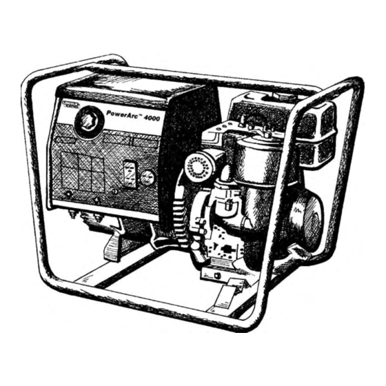
POWER-ARC 4000
For use with machine code number 10083
Safety Depends on You
Lincoln arc welding and cutting
equipment is designed and
built with safety in mind.
However, your overall safety
can be increased by proper
installation . . . and thoughtful
operation on your part. DO
NOT INSTALL, OPERATE OR
REPAIR THIS EQUIPMENT
WITHOUT READING THIS
MANUAL AND THE SAFETY
PRECAUTIONS CONTAINED
THROUGHOUT. And, most
importantly, think before you
act and be careful.
SERVICE MANUAL
World's Leader in Welding and Cutting Products
Premier Manufacturer of Industrial Motors
Sales and Service through subsidiaries and Distributors Worldwide
22801 St. Clair Ave. Cleveland, Ohio 44117-1199 U.S.A. Tel. (216) 481-8100
Advertisement
Chapters
Table of Contents
Troubleshooting

Related Manuals for Lincoln Electric POWER-ARC 4000 SVM103-A


Summary of Contents for Lincoln Electric POWER-ARC 4000 SVM103-A
- Page 1 RETURN TO MAIN INDEX SVM103-A December 1995 POWER-ARC 4000 For use with machine code number 10083 Safety Depends on You Lincoln arc welding and cutting equipment is designed and built with safety in mind. However, your overall safety can be increased by proper installation .
-
Page 2: Safety
351040, Miami, Florida 33135 or CSA Standard W117.2-1974. A Free copy of “Arc Welding Safety” booklet E205 is available from the Lincoln Electric Company, 22801 St. Clair Avenue, Cleveland, Ohio 44117-1199. BE SURE THAT ALL INSTALLATION, OPERATION, MAINTENANCE AND REPAIR PROCEDURES ARE FOR ENGINE powered equipment. - Page 3 ELECTRIC SHOCK can kill. 3.a. The electrode and work (or ground) circuits are electrically “hot” when the welder is on. Do not touch these “hot” parts with your bare skin or wet clothing. Wear dry, hole-free gloves to insulate hands. 3.b.
- Page 4 WELDING SPARKS can cause fire or explosion. 6.a. Remove fire hazards from the welding area. If this is not possible, cover them to prevent the welding sparks from starting a fire. Remember that welding sparks and hot materials from welding can easily go through small cracks and openings to adjacent areas.
- Page 5 PRÉCAUTIONS DE SÛRETÉ Pour votre propre protection lire et observer toutes les instruc- tions et les précautions de sûreté specifiques qui parraissent dans ce manuel aussi bien que les précautions de sûreté générales suivantes: Sûreté Pour Soudage A L’Arc Protegez-vous contre la secousse électrique: Les circuits à...
-
Page 6: Table Of Contents
MASTER TABLE OF CONTENTS FOR ALL SECTIONS Safety...i-iv Installation ...Section A Technical Specifications ...A-1 Safety Precautions...A-2 Location and Ventilation ...A-2 Pre-operation Engine Service ...A-3 Electrical Output Connections...A-4 Operation...Section B Safety Instructions ...B-1 General Description ...B-1 Recommended Applications ...B-2 Operational Features and Controls ...B-2 Design Features and Advantages ...B-2 Welding Capability...B-2 Limitations ...B-2... - Page 7 - INSTALLATION SECTION - Installation Technical Specifications ...A-1 Safety Precautions...A-2 Location and Ventilation ...A-2 Storing ...A-2 Stacking...A-3 Tilting ...A-3 Lifting ...A-3 Pre-operation Engine Service ...A-3 Oil ...A-3 Fuel ...A-3 Muffler Deflector...A-3 Spark Arrester ...A-3 Electrical Output Connections...A-4 Welding Cable Connections...A-4 Cable Size and Length ...A-4 Cable Installation ...A-5 Machine Grounding ...A-5...
-
Page 8: Installation
TECHNICAL SPECIFICATIONS - POWER-ARC 4000 Manufacturer Description Briggs & 1 cyl., Stratton Cool- 4 cycle Bore ® air-cooled gasoline 8 HP @ 3750 RPM Duty Cycle 30% Duty Cycle 60% Duty Cycle OUTPUT - WELDER AND GENERATOR Welding Ranges 70 - 125 Amps Height 20.9 in. -
Page 9: Safety Precautions
Read this entire installation section before you start installation. SAFETY PRECAUTIONS WARNING Do not attempt to use this equipment until you have thoroughly read all the operation and maintenance manuals supplied with your machine. They include important safety precautions; detailed engine starting, operating, and maintenance instructions;... -
Page 10: Pre-Operation Engine Service
STACKING POWER-ARC 4000 machines CANNOT be stacked. TILTING Place the machine on a secure, level surface whenev- er you use it or store it. Any surfaces you place it on other than the ground must be firm, non-skid, and structurally sound. The gasoline engine is designed to run in a level posi- tion for best performance. -
Page 11: Electrical Output Connections
FIGURE A.1 - POWER-ARC 4000 OUTPUT CONNECTIONS WARNING ELECTRODE SELECTION GUIDE 1. CURRENT CONTROL DIAL 2. WELD OUTPUT TERMINALS (2) 3. GROUND STUD ELECTRICAL OUTPUT CONNECTIONS See Figure A.1 for the location of the current control dial, weld output terminals, ground stud, circuit break- ers, 240 and 120 volt receptacles. -
Page 12: Cable Installation
• Do not cross the welding cables at the output termi- nal connection. Keep the cables isolated and sepa- rate from one another. Lincoln Electric offers a welding accessory kit with the properly specified welding cables. See the ACCES- SORIES section of this manual for more information. -
Page 13: Premises Wiring
The POWER-ARC 4000 (unlike other Lincoln Electric equipment) does not have a combined 120/240 volt twist-lock receptacle and cannot be connected to a premises as described in other Lincoln literature. - Page 14 ELECTRICAL DEVICE USE WITH THE POWER-ARC 4000. Type Resistive Capacitive Inductive Capacitive/Inductive The Lincoln Electric Company is not responsible for any damage to electrical components improperly connect- ed to the POWER-ARC 4000. POWER-ARC 4000 INSTALLATION CAUTION TABLE A.2 Common Electrical Devices...
-
Page 15: Recommended Applications
- OPERATION SECTION - Operation...Section B Safety Instructions ...B-1 General Description ...B-1 Recommended Applications ...B-2 Generator Welder Operational Features and Controls ...B-2 Design Features and Advantages ...B-2 Welding Capability...B-2 Limitations ...B-2 Controls and Settings ...B-3 Generator/Welder Controls ...B-3 Gasoline Engine Controls...B-4 Engine Operation ...B-5 Before Starting the Engine ...B-5 Starting the Engine ...B-5... -
Page 16: Operation
OPERATING INSTRUCTIONS Read and understand this entire section before oper- ating your POWER-ARC 4000. SAFETY INSTRUCTIONS WARNING Do not attempt to use this equipment until you have thoroughly read all the operation and maintenance manuals supplied with your machine. They include important safety precautions;... -
Page 17: Recommended Applications
The POWER-ARC 4000 warranty covers the machine for one year from the date of purchase. For non- engine warranty claims, contact your nearest Lincoln Authorized Field Service Facility. For engine warranty claims, contact your nearest Briggs & Stratton service center. NOTE: The POWER-ARC 4000 is not meant for rental or other commercial use. -
Page 18: Controls And Settings
CONTROLS AND SETTINGS All generator/welder controls are located on the Output Control Panel. Gasoline engine controls are mounted on the engine. See Figures B.1 and B.2 and the explanations that follow. FIGURE B.1 – OUTPUT PANEL CONTROLS ELECTRODE SELECTION GUIDE 1. -
Page 19: Gasoline Engine Controls
5. GROUND STUD: Provides a connection point for connecting the machine case to earth ground for the safest grounding procedure. 6. 20 AMP CIRCUIT BREAKERS (2): Provide sepa- rate overload current protection for the 120 volt and 240 volt receptacles. FIGURE B.2 –... -
Page 20: Engine Operation
7. AIR MIXTURE ADJUSTMENT SCREW: Adjusts the amount of air mixed with fuel to obtain the smoothest operation under load or at idle. The POWER-ARC 4000 is shipped with the proper adjustment already set. DO NOT ADJUST THE AIR MIXTURE SCREW WITHOUT FOLLOWING THE PROCEDURES OUTLINED BY BRIGGS &... -
Page 21: Stopping The Engine
4. Pull the cord rapidly. 5. If the engine does not start, open the choke slight- ly (move lever upward) and pull the starter cord rapidly again. When the engine starts, gradually open the choke to the highest, upward position. FOR A “HOT”... -
Page 22: Generator Operation
GENERATOR OPERATION CAUTION Be sure that any electrical equipment plugged into the generator’s AC power receptacles can withstand a ±10% voltage and a ±3% frequency variation. Some electronic devices cannot be powered by the POWER- ARC 4000. Refer to Table A.2, ELECTRICAL DEVICE USE WITH THE POWER-ARC 4000, in the INSTALLA- TION section of this manual. - Page 23 GENERATOR POWER APPLICATIONS Suggested Power Applications *Air Compressor - 3/4 HP *Airless Sprayer - 1/3 HP Chain Saw 1,200 Circular Saw Coffee Maker *Deep Freezer *Electric Motor - 1 HP Electric Range (1 element) Electric Skillet *Furnace Fan - 1/3 HP Portable Grinder (4 1/2”) Portable Grinder (7”) Halogen Work Light...
-
Page 24: Welding Operation
WELDING OPERATION GENERAL INFORMATION WARNING Do not touch electrically live parts or elec- trodes with your skin or wet clothing. Do not breathe welding fumes or gases. Use ventilation or exhaust to remove weld- ing fumes from the breathing area. Keep flammable material away. -
Page 25: Welding Guidelines
Many variables beyond the control of The Lincoln Electric Company affect the results obtained in applying this type of informa- tion. These variables include, but are not... - Page 26 B-11 FIGURE B.3 – WELDING CIRCUIT CONNECTIONS 1. POWER SOURCE 2. ELECTRODE CABLE 3. ELECTRODE HOLDER 4. ELECTRODE 5. OUTPUT TERMINALS 6. WORK 7. WORK CLAMP 8. WORK CABLE THE WELDING CIRCUIT When everything is connected properly, the current from the power source causes the electrode to melt and bond the metal being welded.
- Page 27 FIGURE B.4 – THE WELDING ARC 1. ELECTRODE 2. COATING 3. SHIELDING GAS 4. ARC 5. BASE METAL 6. WELD METAL 7. SOLIDIFIED SLAG Obviously, stick arc welding is a manual skill requir- ing a steady hand, good physical condition, and good eyesight.
- Page 28 4000 for stick welding. For more detailed information, order a copy of the book New Lessons in Arc Welding, available from the Book Division of Lincoln Electric. See the form located at the back of this manual for ordering information!
- Page 29 Accessories...Section C Options/Accessories...C-1 Lincoln Electric Accessories ...C-1 Briggs and Stratton Accessories ...C-1 Semiautomatic Mig Welding with a Lincoln/Weld-Pak 100 or Weld-Pak 125...C-1 TABLE OF CONTENTS - ACCESSORIES - Section C POWER-ARC 4000...
- Page 30 In addition to using the accessories/options listed above, the POWER-ARC 4000 generator can supply power to a Lincoln ELectric Weld-Pak 100 or Weld- Pak 125 wire feed welder. The Weld-Pak comes with all the supplies needed for Flux-Cored Arc Welding (FCAW).
-
Page 31: Routine And Periodic Maintenance
Maintenance ...Section D Routine and Periodic Maintenance ...D-1 Engine Maintenance...D-1 Generator/Welder Maintenance ...D-4 Major Component Locations ...D-5 TABLE OF CONTENTS -MAINTENANCE- Section D POWER-ARC 4000... -
Page 32: Safety Precautions
SAFETY PRECAUTIONS WARNING • Have qualified personnel do all maintenance and troubleshooting work. • Turn the engine off before working inside the machine. • Remove guards only when necessary to perform maintenance and replace them when the mainte- nance requiring their removal is complete. •... - Page 33 AIR CLEANER: Your air cleaner may have only the paper cartridge, or it may have the cartridge and a foam pre-clean- er. If it has the pre-cleaner, service the cartridge every 100 hours and the pre- cleaner every 25 hours or once a year, whichever comes first.
- Page 34 CLEAN OR REPLACE SPARK PLUG: Clean or replace the spark plug after every 100 hours of opera- tion or every season, whichever comes first. Do not blast the spark plug clean with an abrasive cleaning device. Clean the plug by scraping it or by using a wire brush.
-
Page 35: Generator/Welder Maintenance
TABLE D.2 – ENGINE MAINTENANCE PARTS Part OIL FILTER SPARK PLUG (STANDARD) SPARK PLUG (RESISTOR) FUEL FILTER AIR CLEANER CARTRIDGE AIR PRE-CLEANER (AS NEEDED) GENERATOR/WELDER MAINTENANCE STORAGE: Store the POWER-ARC 4000 in clean, dry, protected areas. CLEANING: Blow out the generator and controls periodically with low pressure air. -
Page 36: Major Component Locations
FIGURE D.6. - MAJOR COMPONENT LOCATIONS POWER-ARC 4000 MAINTENANCE 1 . CRADLE ASSEMBLY 2. ROTOR, BLOWER, AND BEARING ASSEMBLY 3. STATOR ASSEMBLY 4. BRUSH AND BRUSH HOLDER ASSEMBLY 5. CONTROL BOX WELDED ASSEMBLY 6. REACTOR ASSEMBLY 7. OUTPUT TERMINAL ASSEMBLY 8. - Page 37 -THEORY OF OPERATION SECTION- Theory of Operation ...Section E Power Supply Operation ...E-1 - E-3 Engine, Excitation, Rotor and Stator ...E-1 Rotor Field Feedback and Auxiliary Power...E-2 Weld Winding and Reactor ...E-3 Auxiliary Power Overcurrent Protection ...E-4 ENGINE MECHANICAL ROTATION RHEOSTAT FIGURE E.1 –...
-
Page 38: Theory Of Operation
FIGURE E.2 – ENGINE, ROTOR AND STATOR ENGINE MECHANICAL ROTATION RHEOSTAT ENGINE, EXCITATION, ROTOR AND STATOR A small DC voltage developed by the flywheel alterna- tor in the Briggs & Stratton engine is fed to the rotat- ing field coil in the rotor via a brush and slip ring con- figuration. -
Page 39: Theory Of Operation
THEORY OF OPERATION FIGURE E.3 – FIELD EXCITATION AND AUXILIARY POWER ENGINE MECHANICAL ROTATION RHEOSTAT ROTOR FIELD FEEDBACK AND AUXILIARY POWER The AC voltage developed in the field winding is fed to the full wave bridge. The DC output of the bridge is fil- tered by the field capacitor and controlled by the out- put rheostat. - Page 40 THEORY OF OPERATION FIGURE E.4 – WELDING OUTPUT SHADE ENGINE MECHANICAL ROTATION RHEOSTAT WELD WINDING AND REACTOR The AC voltage developed in the stator weld winding is delivered, through the reactor, to the machine out- put terminals. The PowerArc 4000 provides the user with 125 amps of constant current AC welding for stick electrodes.
- Page 41 TROUBLE SHOOTING & REPAIR SECTION Troubleshooting & Repair Section...Section F Safety Precautions...F-1 How to Use Troubleshooting Guide ...F-1 Troubleshooting Guide...F1 - F-9 Test Procedures Rotor Voltage Test ...F-10 Rotor Resistance Test...F-12 Engine Throttle Adjustment Test...F-15 Oscilloscope Waveforms Normal Open Circuit Weld Voltage Waveform ...F-18 Normal Open Circuit Weld Voltage Waveform (115 VAC Supply) ...F-19 Typical Weld Output Waveform - Machine Loaded ...F-20 Replacement Procedures...
-
Page 42: Troubleshooting And Repair
TROUBLESHOOTING & REPAIR HOW TO USE TROUBLESHOOTING GUIDE Service and repair should be performed by only Lincoln Electric Factory Trained Personnel. Unauthorized repairs performed on this equipment may result in danger to the technician and machine operator and will invalidate your factory warranty. For your safety and to avoid Electrical Shock, please observe all safety notes and precautions detailed throughout this manual. -
Page 43: Troubleshooting Guide
If for any reason you do not understand the test procedures or are unable to perform the test/repairs safely, con- tact the Lincoln Electric Service Department for electrical troubleshooting assistance before you proceed. Call 216-383-2531 or 1-800-833-9353. detailed in the beginning of this manual. - Page 44 - engine runs normally. If for any reason you do not understand the test procedures or are unable to perform the test/repairs safely, con- tact the Lincoln Electric Service Department for electrical troubleshooting assistance before you proceed. Call 216-383-2531 or 1-800-833-9353.
- Page 45 - engine runs normally. If for any reason you do not understand the test procedures or are unable to perform the test/repairs safely, con- tact the Lincoln Electric Service Department for electrical troubleshooting assistance before you proceed. Call 216-383-2531 or 1-800-833-9353.
- Page 46 - engine runs normally. If for any reason you do not understand the test procedures or are unable to perform the test/repairs safely, con- tact the Lincoln Electric Service Department for electrical troubleshooting assistance before you proceed. Call 216-383-2531 or 1-800-833-9353.
- Page 47 If for any reason you do not understand the test procedures or are unable to perform the test/repairs safely, con- tact the Lincoln Electric Service Department for electrical troubleshooting assistance before you proceed. Call 216-383-2531 or 1-800-833-9353. detailed in the beginning of this manual.
- Page 48 Engine will not start. If for any reason you do not understand the test procedures or are unable to perform the test/repairs safely, con- tact the Lincoln Electric Service Department for electrical troubleshooting assistance before you proceed. Call 216-383-2531 or 1-800-833-9353.
- Page 49 Engine sputters but will not start. If for any reason you do not understand the test procedures or are unable to perform the test/repairs safely, con- tact the Lincoln Electric Service Department for electrical troubleshooting assistance before you proceed. Call 216-383-2531 or 1-800-833-9353.
- Page 50 If for any reason you do not understand the test procedures or are unable to perform the test/repairs safely, con- tact the Lincoln Electric Service Department for electrical troubleshooting assistance before you proceed. Call 216-383-2531 or 1-800-833-9353. POWER-ARC 4000...
-
Page 51: Rotor Voltage Test
TROUBLESHOOTING & REPAIR ROTOR VOLTAGE TEST Service and repair should be performed by only Lincoln Electric factory trained personnel. Unauthorized repairs performed on this equipment may result in danger to the technician or machine operator and will invalidate your factory warranty. For your safety and to avoid elec-... - Page 52 F-11 TROUBLESHOOTING & REPAIR ROTOR VOLTAGE TEST (continued) FIGURE F.1 - LOCATION OF LEAD 200A FOR ROTOR VOLTAGE TEST LEAD 200A CONNECTION TEST PROCEDURE 1. With the 5/16” nut driver, remove the 4 sheet metal screws that hold the top cover to the control box.
-
Page 53: Rotor Resistance Test
TROUBLESHOOTING & REPAIR ROTOR RESISTANCE TEST Service and repair should be performed by only Lincoln Electric factory trained personnel. Unauthorized repairs performed on this equipment may result in danger to the technician or machine operator and will invalidate your factory warranty. For your safety and to avoid elec-... - Page 54 F-13 TROUBLESHOOTING & REPAIR ROTOR RESISTANCE TEST (continued) LOCATION OF ROTOR SLIP RINGS - BRUSH HOLDER ASSEMBLY REMOVED SLIP RINGS TEST PROCEDURE 1. Conduct the test with the gasoline engine OFF. 2. Remove the spark plug wire to prevent accidental engine kickback or starting. 3.
- Page 55 TROUBLESHOOTING & REPAIR ROTOR RESISTANCE TEST (continued) FIGURE F.3 - BRUSHES RETAINED WITH CABLE TIE CABLE BRUSHES 9. Reinstall the brush holder assembly after the test. Depress the spring-loaded brushes into the holder and slip a suitable non-metallic, fairly stiff retainer through the slots at the top and bottom of the holder.
-
Page 56: Engine Throttle Adjustment Test
TROUBLESHOOTING & REPAIR ENGINE THROTTLE ADJUSTMENT TEST Service and repair should be performed by only Lincoln Electric factory trained personnel. Unauthorized repairs performed on this equipment may result in danger to the technician or machine operator and will invalidate your factory warranty. For your safety and to avoid elec-... - Page 57 TROUBLESHOOTING & REPAIR ENGINE THROTTLE ADJUSTMENT TEST (continued) FIGURE F.4 - BLOWER PADDLE MARKED FOR STROBE-TACH METHOD MARK TEST PROCEDURE This test can be conducted by any of three methods. Strobe-tach Method: 1. Stop the engine and remove the spark plug wire to prevent accidental kickback or starting.
- Page 58 F-17 TROUBLESHOOTING & REPAIR ENGINE THROTTLE ADJUSTMENT TEST (continued) 2. Use the 7/16 wrench to turn in the spring-loaded adjustment nut. Increase the high idle speed to adjust the waveform period to 16.2 milliseconds. See Figure F.5 for location of the adjustment nut. FIGURE F.5 - LOCATION OF ENGINE THROTTLE ADJUSTMENT NUT POWER-ARC 4000 12/95...
-
Page 59: Normal Open Circuit Weld Voltage Waveform
TROUBLESHOOTING & REPAIR NORMAL OPEN CIRCUIT WELD VOLTAGE WAVEFORM HIGH IDLE – NO LOAD 50 volts This is the typical AC output voltage generated from a properly operating machine. Note that each vertical division represents 50 volts and that each horizontal division represents 5 milliseconds in time. - Page 60 F-19 TROUBLESHOOTING & REPAIR NORMAL OPEN CIRCUIT VOLTAGE WAVEFORM (115 VAC SUPPLY) 1 Period = 16.2 ms @ 3700 rpm POWER-ARC 4000 HIGH IDLE – NO LOAD 5 ms 20 volts This is the typical AC output voltage generated from a properly operating machine.
- Page 61 TROUBLESHOOTING & REPAIR TYPICAL WELD OUTPUT WAVEFORM MACHINE LOADED 20 volts MACHINE LOADED TO 125 AMPS AT 23 VAC This is the typical AC output voltage generated from a properly operating machine. Note that each vertical division represents 20 volts and that each horizontal division represents 5 milliseconds in time.
-
Page 62: Brush Removal And Replacement
TROUBLESHOOTING & REPAIR BRUSH REMOVAL AND REPLACEMENT Service and repair should be performed by only Lincoln Electric factory trained person- nel. Unauthorized repairs performed on this equipment may result in danger to the tech- nician or machine operator and will invalidate your factory warranty. For your safety and to avoid electrical shock, please observe all safety notes and precautions detailed throughout this manual. - Page 63 TROUBLESHOOTING & REPAIR BRUSH REMOVAL AND REPLACEMENT (continued) FIGURE F.6 - BRUSHES RETAINED WITH CABLE TIE CABLE BRUSHES PROCEDURE 1. Remove the spark plug wire. 2. Open the brush holder assembly cover. Squeeze the 2 tabs and depress the cover at the top with a screw driver or your fin- gernail.
- Page 64 F-23 TROUBLESHOOTING & REPAIR BRUSH REMOVAL AND REPLACEMENT (continued) (continued) PROCEDURE 8. To reinstall the brush holder assembly, depress the spring-loaded brushes into the holder and slip a suitable non-metal- lic, fairly stiff retainer through the slots at the top and bottom of the holder. A cable tie works well;...
-
Page 65: Rheostat Removal And Replacement
TROUBLESHOOTING & REPAIR RHEOSTAT REMOVAL AND REPLACEMENT Service and repair should be performed by only Lincoln Electric factory trained personnel. Unauthorized repairs performed on this equipment may result in danger to the technician or machine operator and will invalidate your factory warranty. For your safety and to avoid elec-... - Page 66 F-25 TROUBLESHOOTING & REPAIR RHEOSTAT REMOVAL AND REPLACEMENT FIGURE F.7 - RHEOSTAT REMOVAL See Figure F.7 for steps 3 - 9. PROCEDURE 1. Remove the spark plug wire. 2. With the 5/16” nut driver, remove the 4 sheet metal screws that hold the top cover to the control box.
-
Page 67: Capacitor And Diode Bridge Removal And Replacement
CAPACITOR AND/OR DIODE BRIDGE REMOVAL AND REPLACEMENT Service and repair should be performed by only Lincoln Electric factory trained personnel. Unauthorized repairs performed on this equipment may result in danger to the technician or machine operator and will invalidate your factory warranty. For your safety and to avoid elec-... - Page 68 F-27 TROUBLESHOOTING & REPAIR CAPACITOR AND/OR DIODE BRIDGE REMOVAL AND REPLACEMENT FIGURE F.8 - DIODE BRIDGE LOCATION AND DISCHARGING THE FIELD CAPACITOR DIODE BRIDGE CAPACITOR PROCEDURE - CAPACITOR REMOVAL AND REPLACEMENT 1. Remove the engine spark plug wire. 2. With the 5/16” nut driver, remove the 4 sheet metal screws that hold the top cover to the control box.
- Page 69 TROUBLESHOOTING & REPAIR CAPACITOR AND/OR DIODE BRIDGE REMOVAL AND REPLACEMENT PROCEDURE - DIODE BRIDGE REMOVAL AND REPLACEMENT 1. To remove the diode bridge, first you will have to remove the field capacitor. Follow Steps 1 - 5 on capacitor removal and replacement procedure.
-
Page 70: Stator/Rotor Removal And Replacement (Kit S20925
TROUBLESHOOTING & REPAIR STATOR/ROTOR REMOVAL AND REPLACEMENT Service and repair should be performed by only Lincoln Electric factory trained personnel. Unauthorized repairs performed on this equipment may result in danger to the technician or machine operator and will invalidate your factory warranty. For your safety and to avoid elec-... - Page 71 TROUBLESHOOTING & REPAIR STATOR/ROTOR REMOVAL AND REPLACEMENT (continued) STATOR REMOVAL PROCEDURE 1. Remove engine spark plug wire to prevent accidental kickback or starting. 2. With the 5/16” nut driver, remove the 4 sheet metal screws that hold the top cover to the control box.
- Page 72 F-31 TROUBLESHOOTING & REPAIR STATOR/ROTOR REMOVAL AND REPLACEMENT (continued) 12. Slide a short length of 2 X 4 under the engine to support it when the stator is removed. 13. With the 1/2” socket wrench, remove the 2 nuts that hold the stator end bracket support.
- Page 73 Pull out the thru- bolt. 3. Install the long thru-bolt supplied with Lincoln Electric Rotor Removal Kit S20925. The slot head must face out. Screw in the bolt with the slot head screw driver until the bolt bottoms out on the engine crankshaft, about 3/4”.
- Page 74 F-33 TROUBLESHOOTING & REPAIR STATOR/ROTOR REMOVAL AND REPLACEMENT (continued) 6. Install the bottom two end bracket thru- bolts. Note: The flat washer goes on the top right hand thru-bolt for the green ground wire. 7. Tap the end bracket with the mallet as necessary to position it.
-
Page 75: Retest After Repair
TROUBLESHOOTING & REPAIR Retest a machine: • If it is rejected under test for any reason that requires you to remove any mechanical part which could affect the machine’s electrical characteristics. • If you repair or replace any electrical components. Maximum Speed Minimum Speed Output Control... - Page 76 F-35 NOTES POWER-ARC 4000...
- Page 77 Section G TABLE OF CONTENTS - ELECTRICAL DIAGRAMS - Electrical Diagrams...Section G PowerArc 4000...G-1 POWER-ARC 4000...
- Page 78 - ELECTRICAL DIAGRAM - WIRING DIAGRAM – Code 10083 NOTE: This diagram is for reference only. It may not be accurate for all machines covered by this manual. The specific diagram for a particular code is pasted inside the machine on one of the enclosure panels. POWER-ARC 4000...
- Page 79 NOTES POWER-ARC 4000...
- Page 80 NOTES POWER-ARC 4000...