Table of Contents
Advertisement
Quick Links
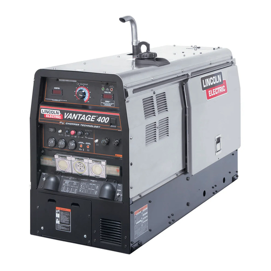
VANTAGE 400 (AU)
For use with machines having Code Numbers:
Safety Depends on You
Lincoln arc welding and cutting
equipment is designed and built
with safety in mind. However,
your overall safety can be
increased by proper installation ...
and thoughtful operation on your
part. DO NOT INSTALL, OPER-
ATE OR REPAIR THIS EQUIP-
MENT WITHOUT READING
THIS MANUAL AND THE SAFE-
TY PRECAUTIONS CONTAINED
THROUGHOUT. And, most
importantly, think before you act
and be careful.
Equipped with VRD (VOLTAGE REDUCTION DEVICE)
See Installation and Operation sections for an explanation.
• Sales and Service through Subsidiaries and Distributors Worldwide •
Cleveland, Ohio 44117-1199 U.S.A. TEL: 216.481.8100 FAX: 216.486.1751 WEB SITE: www.lincolnelectric.com
RETURN TO MAIN MENU
®
11687
OPERATOR'S MANUAL
• World's Leader in Welding and Cutting Products •
Copyright © Lincoln Global Inc.
IM10048
March, 2010
Advertisement
Table of Contents
Troubleshooting

Related Manuals for Lincoln Electric VANTAGE 400 (AU)


Summary of Contents for Lincoln Electric VANTAGE 400 (AU)
- Page 1 VANTAGE 400 (AU) For use with machines having Code Numbers: Safety Depends on You Lincoln arc welding and cutting equipment is designed and built with safety in mind. However, your overall safety can be increased by proper installation ... and thoughtful operation on your part.
-
Page 2: California Proposition 65 Warnings
351040, Miami, Florida 33135 or CSA Standard W117.2-1974. A Free copy of “Arc Welding Safety” booklet E205 is available from the Lincoln Electric Company, 22801 St. Clair Avenue, Cleveland, Ohio 44117-1199. BE SURE THAT ALL INSTALLATION, OPERATION, MAINTENANCE AND REPAIR PROCEDURES ARE PERFORMED ONLY BY QUALIFIED INDIVIDUALS. - Page 3 3.a. The electrode and work (or ground) circuits are electrically “hot” when the welder is on. Do not touch these “hot” parts with your bare skin or wet clothing. Wear dry, hole-free gloves to insulate hands. 3.b. Insulate yourself from work and ground using dry insulation.
- Page 4 6.a. Remove fire hazards from the welding area. If this is not possible, cover them to prevent the welding sparks from starting a fire. Remember that welding materials from welding can easily go through small cracks and openings to adjacent areas. Avoid welding near hydraulic lines.
- Page 5 PRÉCAUTIONS DE SÛRETÉ Pour votre propre protection lire et observer toutes les instructions et les précautions de sûreté specifiques qui parraissent dans ce manuel aussi bien que les précautions de sûreté générales suiv- antes: Sûreté Pour Soudage A L’Arc 1. Protegez-vous contre la secousse électrique: a.
- Page 6 (89/336/EEC). It was manufactured in conformity with a national standard that implements a harmonized standard: EN 60974-10 Electromagnetic Compatibility (EMC) Product Standard for Arc Welding Equipment. It is for use with other Lincoln Electric equipment. It is designed for industrial and professional use. Introduction All electrical equipment generates small amounts of electromagnetic emission.
- Page 7 SAFETY Electromagnetic Compatibility (EMC) The size of the surrounding area to be considered will depend on the structure of the building and other activities that are taking place. The surrounding area may extend beyond the boundaries of the premises. Methods of Reducing Emissions Mains Supply Welding equipment should be connected to the mains supply according to the manufacturer’s recommenda- tions.
-
Page 8: ________________________________________________________________________
Electric for advice or information about their use of our products. We respond to our customers based on the best information in our posses- sion at that time. Lincoln Electric is not in a position to warrant or guarantee such advice, and assumes no liability, with respect to such infor- mation or advice. -
Page 9: Table Of Contents
Machine Grounding ...A-6 Welding Terminals ...A-6 Welding Output Cables ...A-6 Cable Installation...A-6 Auxiliary Power Receptacles and Plugs ...A-7 Standby Power Connections ...A-7 Connection of Lincoln Electric Wire Feeders...A-7,A-8 ________________________________________________________________________________ Operation...Section B Safety Precautions ...B-1 General Description...B-1 For Auxiliary Power ...B-1 Engine Operation...B-1... - Page 10 Fuel ...D-4 Bleeding the Fuel System ...D-4 Fuel Filter ...D-5 Engine Adjustment ...D-5 Battery Maintenance ...D-5 Servicing Optional Spark Arrestor ...D-5 Welder / Generator Maintenance ...D-6 Storage ...D-6 Cleaning...D-6 Brush Removal and Replacement ...D-6 ________________________________________________________________________ Troubleshooting ...Section E How to Use Troubleshooting Guide...E-1 Troubleshooting Guide...E-2 thru E-6...
-
Page 11: Installation
1500 RPM Perkins 404D-22 naturally aspirated Full Load 1500 cold crank amps) water cooled Diesel Engine Low Idle 1200 RATED OUTPUT @ 104° F (40° C) - WELDER Welding Process Current/Voltage/Duty Cycle DC Constant Current DC Pipe Current Touch-Start™TIG DC Constant Voltage Arc Gouging RATED OUTPUT @ 40°... - Page 12 INSTALLATION MACHINE SPECIFICATIONS Receptacles 400V (3 Ph) x 1 230V (1 Ph) x 2 14 Pin Connector 6 Pin Connector Residual Current Device (RCD) 4-pole, 40Amp (30mA trip current) Circuit Breakers (Thermal/Magnetic) 3 Phase, 20 Amp x 1 1 phase, 15 Amp x 2 10A for Engine Battery Charging Circuit Other Circuit Breakers 10A for Wire Feeder Power...
-
Page 13: Safety Precautions
The welder should be located to provide an unrestrict- ed flow of clean, cool air to the cooling air inlets and to avoid restricting the cooling air outlets. Also, locate the welder so that the engine exhaust fumes are prop- erly vented to an outside area. STACKING VANTAGE®... -
Page 14: High Altitude Operation
HIGH TEMPERATURE OPERATION At temperatures above 104°F(40°C), Welder output derating is necessary. For maximum output ratings, derate the welder output 2 volts for every 18°F(10°C) above 104°F(40°C). Cold weather starting: With a fully charged battery and the proper oil, the engine should start satisfactorily down to -15°F(-... -
Page 15: Oil
The standard muffler included with this welder does not qualify as a spark arrester. When required by local regulations, a suitable spark arrester, such as the K903-1 must be installed and properly maintained. -
Page 16: Electrical Connections
WARNING • Be grounded to the frame of the welder using a grounded type plug or be double insulated. • Do not ground the machine to a pipe that carries explosive or combustible material. -
Page 17: Standby Power Connections
"+" terminal of the welder and work cable to the "-" terminal of the welder. For elec- trode Negative, connect the electrode cable to the "-" terminal of the welder and work cable to the "+" terminal of the welder. 3. Across The-Arc Model: •... - Page 18 2. For electrode Positive, connect the electrode cable from the LN-25 to the "+" terminal of the welder and work cable to the "-" terminal of the welder. For electrode Negative, connect the elec- trode cable from the LN-25 to the "-" terminal of the welder and work cable to the "+"...
-
Page 19: Operation
SAFETY PRECAUTIONS WARNING Do not attempt to use this equipment until you have thoroughly read the engine manufacturer’s manual supplied with your welder. It includes important safety precautions, detailed engine starting, operating and maintenance instructions, and parts lists. ------------------------------------------------------------------------ ELECTRIC SHOCK can kill. -
Page 20: Welding Controls
PUT CONTROL is used to set the maximum current range of the OUTPUT CONTROL of the REMOTE. Example: When the OUTPUT CONTROL on the welder is set to 200 amps the current range on the REMOTE CONTROL will be 40-200 amps rather than the full 40-300 amps. Any current range that is less than the full range provides finer current resolution for more fine tuning of the output. - Page 21 4. ARC CONTROL - The ARC CONTROL dial is active in the CV-WIRE, CC-STICK and DOWNHILL PIPE modes, and has different functions in these modes. This control is not active in the TIG and ARC GOUGING mode. CC-STICK mode: In this mode, the ARC CONTROL dial sets the short circuit current (arc-force) during stick welding to adjust for a soft or crisp arc.
-
Page 22: Engine Controls
ENGINE CONTROLS: 12. RUN/STOP SWITCH - RUN position energizes the engine prior to starting. STOP position stops the engine. The oil pressure interlock switch prevents bat- tery drain if the switch is left in the RUN position and the engine is not operating. 13. -
Page 23: Stopping The Engine
STOP position. NOTE: A fuel shut off valve is located on the fuel pre- filter. WELDER OPERATION DUTY CYCLE Duty Cycle is the percentage of time the load is being applied in a 10 minute period. For example a 60% duty cycle, represents 6 minutes of load and 4 minutes of no load in a 10 minute period. -
Page 24: Tig Welding
The OUTPUT CONTROL dial adjusts the full output range for pipe welding. The ARC CONTROL dial sets the short circuit current (arc-force) during stick welding to adjust for a soft or more forceful digging arc (crisp). Increasing the number from -10(soft) to +10(crisp) increases the short circuit current which results in a more forceful digging arc. -
Page 25: Wire Welding-Cv
This will keep the "Solid State" contactor open and provide a "cold" electrode until the Amptrol or Arc Start Switch is pressed. When using the TIG Module, the OUTPUT CONTROL on the VANTAGE® 400 (AU) is used to set the maximum range of the CURRENT CONTROL on the TIG Module or an Amptrol if con- nected to the TIG Module. -
Page 26: Accessories
K857 25 ft (7.6m) or K857-1 100 ft. (30.4m) REMOTE CONTROL Portable control provides same dial range as the output con- trol on the welder. Has a convenient 6 pin plug for easy con- nection to the welder. K1858-1 Service Indicator Kit- Provides a GO / NO-GO visual indication of air cleaner element useful service life. -
Page 27: Maintenance
SAFETY PRECAUTIONS WARNING • Have qualified personnel do all maintenance and troubleshooting work. • Turn the engine off before working inside the machine or servicing the engine. • Remove guards only when necessary to perform maintenance and replace them when the maintenance requiring their removal is complete. -
Page 28: Engine Oil Change
• Locate oil drain hose and valve in bottom of base and pull through the hole in the battery access panel on the welder. • Open oil drain valve by lifting up spring loaded lever and rotate 90 counterclockwise. - Page 29 Single- and Two-Stage Engine Air Cleaners Single- and Two-Stage Engine Air Cleaners Rotate the filter while pulling straight out. Wipe both sides of the outlet tube clean. Outer edge of the outlet tube If your air cleaner is equipped with a Vacuator Valve MAINTENANCE Inner edge of the outlet tube...
-
Page 30: Cooling System
COOLING SYSTEM WARNING HOT COOLANT • Do not remove cap if radiator is hot. ------------------------------------------------------------------------ Check the coolant level by observing the level in the radiator and recovery bottle. Add 50/50 antifreeze / water solution if the level is close to or below the "LOW"... -
Page 31: Fuel Filter
● CONNECTING A BATTERY CHARGER — remove battery from welder by disconnecting negative cable first, then positive cable and battery clamp. When reinstalling, connect negative cable last. Keep well ventilated. -
Page 32: Welder / Generator Maintenance
WARNING • Service and Repair should only be performed by Lincoln Electric Factory Trained Personnel. Unauthorized repairs performed on this equip- ment may result in danger to the technician and machine operator and will invalidate your factory warranty. -
Page 33: Troubleshooting
HOW TO USE TROUBLESHOOTING GUIDE Service and Repair should only be performed by Lincoln Electric Factory Trained Personnel. Unauthorized repairs performed on this equipment may result in danger to the technician and machine operator and will invalidate your factory warranty. For your safety and to avoid Electrical Shock, please observe all safety notes and precautions detailed throughout this manual. -
Page 34: Troubleshooting
Observe all Safety Guidelines detailed throughout this manual PROBLEMS (SYMPTOMS) Major Physical or Electrical Damage is Evident. Engine will not "crank". Engine will "crank" but not start. Engine shuts down shortly after starting. If for any reason you do not understand the test procedures or are unable to perform the tests/repairs safely, contact your Local Lincoln Authorized Field Service Facility for technical troubleshooting assistance before you proceed. - Page 35 3. Faulty engine alternator or charg- er module. Consult authorized Engine Service Shop. 1. Idler switch in High idle position. Set switch to Auto. 2. External load on welder or auxil- iary power. Remove all external loads. 3. Faulty PC board or idler sole- noid.
- Page 36 Observe all Safety Guidelines detailed throughout this manual PROBLEMS (SYMPTOMS) Engine will not go to high idle when using auxiliary power. Engine will not go to high idle under weld or auxiliary loading. Engine does not develop full power. Engine runs rough. Engine will not go to high idle when attempting to weld or using auxil- iary power.
- Page 37 2. "Weld Terminals" switch in wrong position. Place switch in "Weld Terminals On" position when welding without control cable. 3. Faulty PC board or welder alterna- tor. 1. Poor remote/control cable connec- tion to 6-pin or 14-pin connector. Check connections.
- Page 38 3. "Weld Terminals" switch in wrong position. Place switch in "Weld Terminals On" position when welding without control cable. 4. Faulty PC board or welder alterna- tor. 1. Ensure VRD ON/OFF switch is in the “ON” position. 2. If light is burned out, replace both VRD lights.
- Page 39 DIAGRAMS VANTAGE® 400 (AU)
- Page 40 DIAGRAMS VANTAGE® 400 (AU)
- Page 41 DIAGRAMS VANTAGE® 400 (AU)
- Page 42 DIAGRAMS VANTAGE® 400 (AU)
- Page 43 WIRING DIAGRAM VANTAGE® 400 (AU)
- Page 44 DIMENSION PRINT VANTAGE® 400 (AU)
- Page 45 NOTES VANTAGE® 400 (AU)
- Page 46 NOTES VANTAGE® 400 (AU)
- Page 47 ● WARNING ● Spanish ● AVISO DE PRECAUCION ● French ● ATTENTION ● ● German WARNUNG ● Portuguese ● ATENÇÃO ● Japanese Chinese Korean Arabic ● ● ● ● ● ● ● ● ● ●...
- Page 48 ● ● ● ● ● ● ● ● ● ● ● ● ● ● ● ● ● ● Spanish ● PRECAUCION French ● ● German Portuguese ● ● Japanese Chinese Korean Arabic WARNING AVISO DE ATTENTION WARNUNG ATENÇÃO...
- Page 49 • World's Leader in Welding and Cutting Products • • Sales and Service through Subsidiaries and Distributors Worldwide • Cleveland, Ohio 44117-1199 U.S.A. TEL: 216.481.8100 FAX: 216.486.1751 WEB SITE: www.lincolnelectric.com...