Table of Contents
Troubleshooting

Related Manuals for Endress+Hauser J22


Summary of Contents for Endress+Hauser J22
- Page 1 BA02152C/66/EN/03.22 70198456 Products Solutions Services Valid since version: V 01.04 (device firmware) Operating Instructions J22 TDLAS Gas Analyzer ATEX/IECEx/UKEX: Zone 1 cCSAus: Class I, Division 1/Zone 1...
- Page 2 Operating Instructions J22 TDLAS Gas Analyzer Endress+Hauser...
-
Page 3: Table Of Contents
7.2 Configuring the measuring device ...... 60 Product description ......11 7.3 Defining the tag name .......... 61 3.1 J22 TDLAS Gas Analyzer model types ....11 7.4 Setting the analyte type ........61 3.2 Sample conditioning system components ..13 7.5 Selecting the measurement calibration .... - Page 4 Operating Instructions J22 TDLAS Gas Analyzer 9.3 Diagnostic information in the web browser ..92 11.3 J22 TDLAS Gas Analyzer on panel ....115 9.4 Diagnostic information through the 11.4 J22 TDLAS Gas Analyzer with enclosure ..116 communication interface ........93 11.5 Controller spare parts details......
-
Page 5: Introduction
Operating Instructions Introduction Document function This operating instruction contains information required to install and operate the J22 TDLAS Gas Analyzer. It is important to closely review the sections of this manual to ensure the analyzer performs as specified. Symbols used 1.2.1... -
Page 6: Standard Documentation
The document contains all the technical data on the analyzer. For additional instruction manuals, please refer to the following: • For custom orders, go to the Endress+Hauser website for the list of local sales channels who can provide the requested order-specific documentation: https://endress.com/contact https://addresses.endress.com/... -
Page 7: Safety
Laser safety The J22 TDLAS Gas Analyzer is a Class 1 laser product, which poses no threat to equipment operators. The laser internal to the analyzer controller is classified Class 3R and could cause eye damage if the beam is viewed directly. -
Page 8: Product Safety
J22 TDLAS Gas Analyzer Product safety The J22 TDLAS Gas Analyzer is designed in accordance with good engineering practice to meet state-of-the-art safety requirements, has been tested, and left the factory in a condition in which it is safe to operate. -
Page 9: Device-Specific It Security
The web server is enabled when the device is delivered. The web server can be disabled if necessary (e.g., after commissioning) from the web server functionality parameter. The J22 TDLAS Gas Analyzer and status information can be hidden on the login page. This prevents unauthorized access to the information. - Page 10 Operating Instructions J22 TDLAS Gas Analyzer 2.4.5 Access through service interface The device can be accessed from the service interface (CDI-RJ45). Device specific functions guarantee the secure operation of the device in a network. Connection to the service interface (CDI-RJ45) shall only be permitted by trained personnel on a temporary basis for the purpose of test, repair or overhaul of the equipment, and only if the area where the equipment is to be installed is known to be non-hazardous.
-
Page 11: Product Description
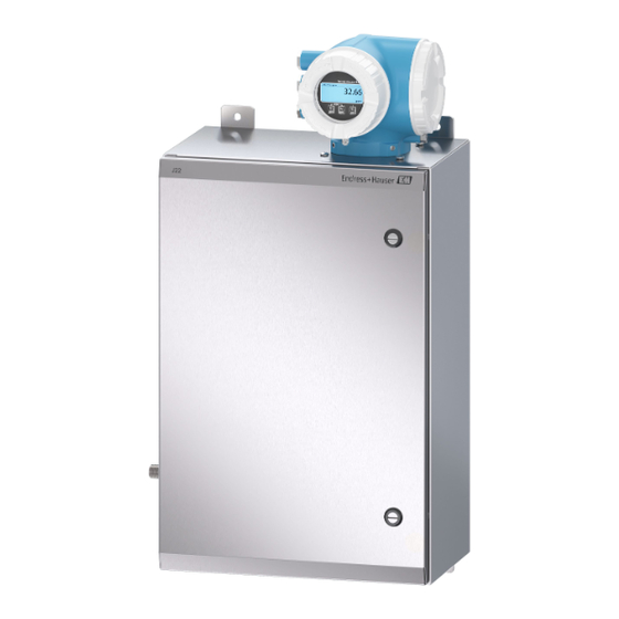
Operating Instructions Product description J22 TDLAS Gas Analyzer model types The J22 TDLAS Gas Analyzer is available in several configurations, including the stand-alone analyzer or an analyzer with sample system panel mount or enclosure. Fig 1. J22 TDLAS Gas Analyzer configuration... - Page 12 Operating Instructions J22 TDLAS Gas Analyzer Fig 3. J22 TDLAS Gas Analyzer on panel with flow meter options (2) Controller Optical head enclosure assembly Measurement cell assembly Flow meters (bypass and analyzer, optional) Flow sensor wire (optional) Armored flow meters (optional) Fig 4.
-
Page 13: Sample Conditioning System Components
Sample conditioning system components A sample conditioning system (SCS) is optional with the J22. The SCS has been specifically designed to deliver a sample stream that is representative of the process systems stream at the time of sampling. J22 analyzers are designed for use with extractive natural gas sampling stations. -
Page 14: Equipment Labels
Operating Instructions J22 TDLAS Gas Analyzer Equipment labels 3.4.1 Nameplate Fig 6. J22 analyzer nameplate Manufacturing name and location Document number of safety-related supplementary Product name documentation Order code Space for approvals and certificates: e.g., CE mark Serial number (SN) -
Page 15: Symbols On The Equipment
J22 TDLAS Gas Analyzer Operating Instructions Symbols on the equipment 3.5.1 Electrical symbols Symbol Description Protective Earth (PE) A terminal which is bonded to conductive parts of equipment for safety purposes and is intended to be connected to an external protective earthing system. -
Page 16: Installation
Installing the heat trace boot The heat trace boot for J22 TDLAS Gas Analyzer with an enclosure is an available option. For ease of shipping, the heat trace boot may have been removed at the factory. To reinstall the heat trace boot, follow the instructions below. - Page 17 A sunshade or canopy installed over the analyzer for outdoor installations is recommended in those instances. Hardware used for mounting the J22 TDLAS Gas Analyzer must be able to support four times the weight of the device, approximately 19 kg (40 lbs) to 43 kg (95 lbs) depending on configuration.
- Page 18 4.3.3 Plate mounting The plate mounting option is designed for users who will install the J22 analyzer within their own enclosure. The J22 should be installed vertically with the analyzer controller exposed to the exterior of the enclosure. When mounting the analyzer, position the instrument so that it is not difficult to operate adjacent devices.
- Page 19 When mounting the analyzer, position the instrument so that it is not difficult to operate adjacent devices. Hardware used mounting the J22 TDLAS Gas Analyzer must be able to support four times the weight of the device, approximately 19 kg (40 lbs) to 43 kg (95 lbs) depending on configuration.
- Page 20 Place clamps on post based on the system configuration. System Type Distance (mm) Distance (in.) J22 TDLAS Gas Analyzer with SCS on Panel 13.3 J22 TDLAS Gas Analyzer with Enclosed SCS 25.2 Repeat steps 1 through 6 for second support rail.
-
Page 21: Turning The Display Module
J22 TDLAS Gas Analyzer Operating Instructions Fig 14. Support rail installation Insert washers and M8 nuts on the back side of the support rail. Torque bolts to 20.75 Nm (183.7 lb-in.). Turning the display module The display module can be turned to optimize readability and operability. -
Page 22: Electrical Connections
Use copper conductors only. For models of the J22 TDLAS Gas Analyzer with the SCS mounted within an enclosure, the inner sheath of the supply cable for the heater circuit shall be sheathed with thermoplastic, thermosetting, or elastometric material. - Page 23 Terminals 26 and 27 are used for Modbus RTU (RS485) only. Terminals 26 and 27 are replaced by an RJ45 connector for Modbus TCP. N.C. is used for “No connection.” Connector J7 on the optical head is for Endress+Hauser factory connection only. Do not use for installation or customer connection.
- Page 24 Push the cable through the cable entry. To ensure tight sealing, do not remove the sealing ring from the cable entry. ° ° The temperature of the J22 TDLAS Gas Analyzer can reach 67 C in 60 C ambient at the cable entry and branching point. This must be considered when selecting field wiring and cable entry devices.
- Page 25 J22 TDLAS Gas Analyzer Operating Instructions Step 5 is not used for CSA-certified products. Under CEC and NEC requirements, conduit is used in place of cable glands. A0033984 Fig 22. Connecting the cables and tightening glands Close the terminal cover.
- Page 26 Screw on the connection compartment cover. Secure the securing clamp of the connection compartment cover. 4.6.4 Connecting the supply voltage and additional inputs/outputs The temperature of the J22 TDLAS Gas Analyzer can reach 67 ° C in 60 ° C ambient at the cable entry and branching point.
- Page 27 Screw on the connection compartment cover. Secure the securing clamp of the connection compartment cover. Conduit is required for the power connection for the CSA certified J22 TDLAS Gas Analyzer. The ATEX-certified model requires armored cable steel wire or braided wire.
- Page 28 Ground wire is not installed for CSA thermostat. Only applies to ATEX version. G/Y Green/yellow wire For models of the J22 TDLAS Gas Analyzer with the SCS mounted within an enclosure, the inner sheath of the supply cable for the heater circuit shall be sheathed with thermoplastic, thermosetting, or elastometric material.
- Page 29 Conduit seals and glands specific to the application should be used where appropriate in compliance with local regulations. For models of the J22 TDLAS Gas Analyzer with enclosed SCS featuring a heater with optional imperial connections, a suitable equipment seal shall be installed within 5 cm. (2 in.) of the outer enclosure wall of the heating circuit.
- Page 30 4.6.9 Connecting the flow switch The J22 TDLAS Gas Analyzer can be offered with a variable flow meter equipped with an optional mechanical display and reed contact to measure the volume flow of flammable and non-flammable gases. Installation shall be in accordance with the National Electric Code NFPA 70, Article 500 to 505, ANSI/ISA-RP ...
-
Page 31: Gas Connections
Threaded entries Gas connections Once you have verified that the J22 TDLAS Gas Analyzer is functional and that the analyzer circuit is de-energized, you are ready to connect the sample supply, sample purge, pressure relief vent (if applicable), validation source (if applicable) and purge supply (if applicable) gas lines. -
Page 32: Metric Conversion Kit
A metric conversion kit for the sample system converts the Imperial (inch) analyzer system fittings to metric (mm) fittings. This kit can be provided with the J22 TDLAS Gas Analyzer at the time of product ordering. The kit includes the following parts:... -
Page 33: Hardware Settings
Refer to Swagelok’s manufacturer instructions. Hardware settings Refer to the following figure during the hardware start-up operation. Fig 34. J22 TDLAS Gas Analyzer flow diagram for fully loaded (A) and minimum (B) sample systems Sample supply valve (2- or 3-way) 7 Validation inlet... - Page 34 In normal operation, the alarm has a 60 second delay. 4.9.2 Setting the J22 TDLAS Gas Analyzer address Depending on the fieldbus, the hardware addressing works differently; Modbus RS485 uses a device address, or Modbus TCP, uses an IP address.
- Page 35 A0029632 Fig 37. Off/on DIP switch selection for enabling the terminating resistor Hardware addressing for Modbus TCP The IP address for the J22 can be configured from DIP switches. Addressing data The IP address and configuration options are listed below:...
- Page 36 Operating Instructions J22 TDLAS Gas Analyzer Setting the IP address Risk of electric shock when opening the controller housing. Disconnect from power supply before opening the controller housing. The default IP address may not be activated. A0029635 Fig 38. DIP switches for setting the IP address Loosen the securing clamp of the connection compartment cover.
-
Page 37: Ensuring Ip66 Degree Of Protection
J22 TDLAS Gas Analyzer Operating Instructions 4.10 Ensuring IP66 degree of protection The measuring device fulfills all the requirements for the IP66 degree of protection, Type 4X enclosure. To guarantee IP66 degree of protection, Type 4X enclosure, carry out the following steps after the electrical connection: Check that the housing seals are clean and fitted correctly. -
Page 38: Operation Options
Operating Instructions J22 TDLAS Gas Analyzer Operation options Overview of operation options Fig 41. Operation options Local operation through the display module Computer with web browser (e.g., Internet Explorer) Cell device (or tablet) used on the network to access the web server or Modbus Control system (e.g., PLC) -
Page 39: Structure And Function Of The Operating Menu
J22 TDLAS Gas Analyzer Operating Instructions Structure and function of the operating menu A0018237_SSI Fig 42. Schematic structure of the operating menu 5.2.1 Operating roles The individual parts of the operating menu are assigned to certain user roles (operator, maintenance, etc.). Each user role contains typical tasks within the device lifecycle. - Page 40 Operating Instructions J22 TDLAS Gas Analyzer Functional role/Menu User Role and Tasks Content/Meaning • Defining the operating language Task Role Operator, Maintenance Display • Defining the web server operating language Oriented Language Tasks during operation: • Configuring the • Configuring the operational display (e.g.,...
-
Page 41: Local Operation
J22 TDLAS Gas Analyzer Operating Instructions Local operation A0026785 Fig 43. Operation with touch control Display elements • 4-line, illuminated, graphic display • White background lighting; switches to red in event of device errors • Format for displaying measured variables and status variables can be individually configured •... - Page 42 Operating Instructions J22 TDLAS Gas Analyzer Status area The following symbols appear in the status area of the operational display at the top right: • Status signals→ • F. Failure • C. Function check • S. Out of specification •...
- Page 43 J22 TDLAS Gas Analyzer Operating Instructions 5.4.2 Navigation view In the Submenu In the Wizard Fig 45. Navigation view Navigation view Navigation path to current position Status area Display area for navigation Operating elements → Navigation path The navigation path, displayed at the top left in the navigation view, consists of the following elements: •...
- Page 44 Operating Instructions J22 TDLAS Gas Analyzer Symbol Meaning Setup • In the menu next to the Setup selection • At the left in the navigation path in the Setup menu Diagnostics • In the menu next to the Diagnostics selection •...
- Page 45 J22 TDLAS Gas Analyzer Operating Instructions 5.4.3 Editing view In the Submenu In the Wizard A0013941 A001399 Fig 46. Editing view in the submenu and in the wizard Editing view Display area of the entered values Input mask Operating elements → ...
-
Page 46: Operating Elements
Operating Instructions J22 TDLAS Gas Analyzer Symbol Meaning Selection of special characters. Confirms selection. Switches to the selection of the correction tools. Exits the input without applying the changes. Clears all entered characters. Correction symbols under Symbol Meaning Clears all entered characters. - Page 47 J22 TDLAS Gas Analyzer Operating Instructions Symbol Meaning Escape key combination (press keys simultaneously) In a menu, submenu • Pressing the key briefly: • Exits the current menu level and takes you to the next higher level. • If help text is open, closes the help text of the parameter.
- Page 48 Operating Instructions J22 TDLAS Gas Analyzer Example: Setting the number of displayed measured values to 2 values A0029562-EN Fig 48. Setting the number of displayed measured values to 2 values 5.5.3 Calling up help text Help text is available for some parameters and can be called up from the navigation view. The help text provides a brief explanation of the parameter function and thereby supports swift and safe commissioning.
- Page 49 J22 TDLAS Gas Analyzer Operating Instructions Example: Changing the tag name in the Tag description parameter from 001-FT-101 to 001-FT-102 A0029563-EN Fig 50. Changing the tag name in “Tag description” parameter A message is displayed if the value entered is outside the permitted value range.
- Page 50 Operating Instructions J22 TDLAS Gas Analyzer Access authorization to parameters: Maintenance user role Access Code Status Read Access Write Access An access code has not yet been defined (Factory setting). After an access code has been defined. ...
-
Page 51: Access To The Operating Menu From The Web Browser
J22 TDLAS Gas Analyzer Operating Instructions Access to the operating menu from the web browser Thanks to the integrated web server, the device can be operated and configured through a web browser through a service interface (CDI-RJ45) and connected for Modbus TCP signal transmission. The structure of the operating menu is the same as for the local display. - Page 52 Operating Instructions J22 TDLAS Gas Analyzer Measuring device Interface Settings CDI-RJ45 Measuring device The measuring device has an RJ45 interface. Web server Web server must be enabled; Factory setting: ON. For information on enabling the web server → . IP address If the IP address of the device is not known: •...
- Page 53 J22 TDLAS Gas Analyzer Operating Instructions Turn on the measuring device. Connect to the computer using a cable → . If a second network card is not used, close all the applications on the notebook. Applications requiring Internet or a network, such as email, SAP applications, Internet or Windows Explorer.
- Page 54 Operating Instructions J22 TDLAS Gas Analyzer If a login page does not appear, or if the page is incomplete → . 5.6.4 Logging on Select the preferred operating language for the web browser. Enter the user-specific access code. Access code 0000 (Factory setting);...
- Page 55 J22 TDLAS Gas Analyzer Operating Instructions Functions Meaning Logout End the operation and call up the login page. Navigation area If a function is selected in the function bar, the submenus of the function open in the navigation area. The user can now navigate through the menu structure.
-
Page 56: Remote Operation Using Modbus
Operating Instructions J22 TDLAS Gas Analyzer Remote operation using Modbus 5.7.1 Connecting the analyzer through Modbus RS485 protocol This communication interface is available through Modbus RTU over RS485. A0029437 Fig 55. Connecing through Modbus RTU over RS485 protocol Computer with web browser (e.g., Internet Explorer) for temporarily accessing the device web server (for settings and diagnostics) Automation / control system (e.g., PLC) -
Page 57: Modbus Communication
J22 TDLAS Gas Analyzer Operating Instructions Modbus communication Overview of device description files Current version data for the device. • On the title page of the Operating instructions Firmware version 01.04 • Diagnostics → Device information → Firmware version Release date of firmware version 11.2022... -
Page 58: Modbus Data Map
Operating Instructions J22 TDLAS Gas Analyzer Modbus data map Function of the Modbus data map The device offers a special memory area, the Modbus data map (for a maximum of 16 device parameters), to allow users to call up multiple device parameters through Modbus RS485 or Modbus TCP and not only individual device parameters or a group of consecutive device parameters. -
Page 59: Modbus Registers
J22 TDLAS Gas Analyzer Operating Instructions Data area Modbus RS485 or Modbus Device parameter value Data type Access TCP register Value of scan list register 0 5051 Integer/float Read/write Value of scan list register 1 5053 Integer/float Read/write Value of scan list register . . . -
Page 60: Commissioning
Operating Instructions J22 TDLAS Gas Analyzer Commissioning Language Factory setting: English Configuring the measuring device The Setup menu with its guided wizards contains all the parameters needed for standard operation. Navigation to the Setup menu A0029700-EN Fig 57. Local display example Depending on the device version, not all submenus and parameters are available in every device. -
Page 61: Defining The Tag Name
J22 TDLAS Gas Analyzer Operating Instructions Setup Relay output 1 to n → Display → Advanced setup → Defining the tag name To enable fast identification of the measuring point within the system, you can enter a unique designation using the Device tag parameter and thus change the Factory setting. -
Page 62: Setting System Units
Operating Instructions J22 TDLAS Gas Analyzer Setting system units In the System units submenu, the units of all the measured values can be set. Depending on the device version, not all submenus and parameters are available in every device. The selection can vary depending on the order code. -
Page 63: Setting Peak Tracking
J22 TDLAS Gas Analyzer Operating Instructions Parameter overview with brief description Parameter Prerequisite Description User entry Factory setting • Off Dew point Sets the method used to calculate — ASTM2 • ASTM method 1 dew point temperature. • ASTM • ISO •... -
Page 64: Configuring The Communication Interface
Operating Instructions J22 TDLAS Gas Analyzer User Factory Parameter Prerequisite Description entry setting • Reset Peak track average Sets number of measurements before Positive Used if peak tracking is set above. number making a peak tracking adjustment. integer Configuring the communication interface The Communication submenu guides you systematically through all the parameters that have to be configured for selecting and setting the communication interface. -
Page 65: Configuring The Current Input
J22 TDLAS Gas Analyzer Operating Instructions Factory Parameter Prerequisite Description User entry setting Parity Modbus RS485 device Select parity bits. Picklist ASCII Even option: • 0 = Even option • 1 = Odd option Picklist RTU option: • 0 = Even option •... -
Page 66: Configuring The Current Output
Operating Instructions J22 TDLAS Gas Analyzer Parameter overview with brief description Parameter Prerequisite Description User entry Factory setting • 4...20 mA Select current range for Current span — Approval-specific: • 4...20 mA NE process value output and • 4...20 mA NE •... - Page 67 J22 TDLAS Gas Analyzer Operating Instructions Parameter overview with brief description Parameter Prerequisite Description User entry Factory setting • Off Select process variable for Pro.var. outp — Concentration • Concentration current output. • Dew point 1 • Dew point 2 •...
-
Page 68: Configuring The Switch Output
Operating Instructions J22 TDLAS Gas Analyzer 7.12 Configuring the switch output The switch output wizard guides you systematically through all the parameters that can be set for configuring the selected output type. Navigation Setup menu → switch output ▸ Switch output 1 to n Operating mode →... -
Page 69: Configuring The Relay Output
J22 TDLAS Gas Analyzer Operating Instructions Parameter Prerequisite Description User entry Factory setting • Dew point 2 • Off The Status option is selected Assign status Select the device status for switch • Validation in the Switch output function output. -
Page 70: Configuring The Local Display
Operating Instructions J22 TDLAS Gas Analyzer Parameter Prerequisite Description User entry Factory setting • Not used Terminal — Shows the terminal numbers — • 24-25 (I/O 2) number used by the relay output • 22-23 (I/O 3) module. • Off... - Page 71 J22 TDLAS Gas Analyzer Operating Instructions Value 4 display → Parameter overview with brief description Parameter Prerequisite Description User entry Factory setting • 1 value, max. size Format display A local display is Select how measured 1 value, max. size •...
-
Page 72: Advanced Settings
Operating Instructions J22 TDLAS Gas Analyzer 7.15 Advanced settings The Advanced setup submenu together with its submenus contains parameters for specific settings. Navigation to the Advanced setup submenu A0029564-EN-SSI Fig 59. Navigtion to advanced setup menu The number of submenus can vary depending on the device version. Some submenus are not dealt with in the Operating Instructions. - Page 73 J22 TDLAS Gas Analyzer Operating Instructions 7.15.1 Stream submenu In the stream submenu, you can set parameters related to the stream that needs to be measured. Navigation Setup menu → Advanced setup → Stream ▸ Stream Analyte type → ...
- Page 74 Operating Instructions J22 TDLAS Gas Analyzer 7.15.2.1 Calibration 1 to n submenu Up to four calibrations are available. Only the active calibration will be displayed at any one time. Navigation Setup menu → Advanced setup → Sensor adjustment → Calibration ▸...
- Page 75 J22 TDLAS Gas Analyzer Operating Instructions ▸ Calibration 1 to n Hydrogen sulfide H2S → Hydrogen H2 → Parameter overview with brief description The term “mol” in the table below is an abbreviation for mole fraction. Factory Parameter...
- Page 76 Operating Instructions J22 TDLAS Gas Analyzer Decimal places 3 → ▸ Display Value 4 display → Decimal places 4 → Display language → Display interval → Display damping → Header → Header text →...
- Page 77 J22 TDLAS Gas Analyzer Operating Instructions Factory Parameter Prerequisite Description User entry setting A selection was made in the Enter 0% value for bar graph Signed floating-point 700 mbar a bargraph Value 3 display parameter. display. number value 3 100%...
- Page 78 Operating Instructions J22 TDLAS Gas Analyzer ▸ Configuration backup Operating time → Last backup → Configuration management → Backup state → Comparison result → Parameter overview with brief description Parameter Description User interface/User entry Factory setting...
-
Page 79: Operation
J22 TDLAS Gas Analyzer Operating Instructions Operation Reading measured values With the Measured values submenu, it is possible to read all the measured values. Navigation Diagnostics menu → Measured values ▸ Measured values ▸ Measured variables → ▸ Input values →... - Page 80 Operating Instructions J22 TDLAS Gas Analyzer 8.1.2.1 Current Input 1 to n submenu The Current Input 1 to n submenu contains all the parameters needed to display the current measured values for every current input. Navigation Diagnostics menu → Measured values → Input values → Current input 1 to n ▸...
-
Page 81: Showing Data Logging
J22 TDLAS Gas Analyzer Operating Instructions Parameter overview with brief description Parameter Prerequisite Description User interface/User entry Factory setting The Switch option is Displays the current Switch status 1 to n Open — selected in the Operating ’switch’ output Closed mode parameter. - Page 82 Operating Instructions J22 TDLAS Gas Analyzer Navigation Diagnostics menu → Data logging ▸ Data logging Assign channel 1 to n → Logging interval → Clear logging data → Data logging → Logging delay → Data logging control →...
-
Page 83: Adapting The Measuring Device To The Process Conditions
J22 TDLAS Gas Analyzer Operating Instructions User interface/User Factory Parameter Prerequisite Description entry setting Entire In the Data logging parameter, Displays the total logging Positive floating point logging the Not overwriting option is duration. number duration selected. Adapting the measuring device to the process conditions The following are available for this purpose: •... - Page 84 Operating Instructions J22 TDLAS Gas Analyzer Parameter overview with brief description Parameter Description User entry Factory setting • Not used I/O module 1 to n terminal Shows the terminal numbers • 26-27 (I/O 1) numbers used by the I/O module.
-
Page 85: Simulation
J22 TDLAS Gas Analyzer Operating Instructions Parameter overview with brief description Parameter Description User entry Restrict write-access to parameters to protect the Max. 16-digit character string comprising Define access code configuration of the device against unintentional numbers, letters and special characters changes. -
Page 86: Protecting Settings From Unauthorized Access
(depends on the simulation category selected) Protecting settings from unauthorized access The following write protection options exist in order to protect the J22 TDLAS Gas Analyzer software configuration from unintentional modification: • Protect access to parameters with access code •... - Page 87 J22 TDLAS Gas Analyzer Operating Instructions Enter the access code again in the Confirm access code parameter → to confirm the code. The -symbol appears in front of all write-protected parameters. The device automatically locks the write-protected parameters again if a key is not pressed for 10 minutes in the navigation and editing view.
- Page 88 Operating Instructions J22 TDLAS Gas Analyzer Write protection switch prevents editing of parameter values through the following: • Local display • Modbus RS485 protocol • Modbus TCP protocol Set the write protection (WP) switch No. 1 on the main electronics module to the ON position to enable hardware write protection.
-
Page 89: Verification, Diagnostics And Troubleshooting
J22 TDLAS Gas Analyzer Operating Instructions Verification, diagnostics and troubleshooting Diagnostic information from light emitting diodes 9.1.1 Controller Different LEDs in the controller provide information on the device status. A0029629 Fig 63. LED diagnotics indicators Supply voltage Device status Not used... -
Page 90: Diagnostic Information On Local Display
Operating Instructions J22 TDLAS Gas Analyzer Diagnostic information on local display 9.2.1 Diagnostic message Faults detected by the self-monitoring system of the measuring device are displayed as a diagnostic message in alternation with the operational display. A0029426-EN Fig 64. Diagnotic message... - Page 91 J22 TDLAS Gas Analyzer Operating Instructions 9.2.1.3 Diagnostic information The fault can be identified using the diagnostic information. The Short text helps you by providing information about the fault. In addition, the corresponding symbol for the Diagnostic behavior is displayed in front of the diagnostic information on the local display.
-
Page 92: Diagnostic Information In The Web Browser
Operating Instructions J22 TDLAS Gas Analyzer The user is in the diagnostic message. Press ( symbol) The Diagnostic list submenu opens. Select the desired diagnostic event with or and press . The message for the remedial measures for the selected diagnostic event opens. -
Page 93: Diagnostic Information Through The Communication Interface
J22 TDLAS Gas Analyzer Operating Instructions Symbol Meaning Out of specification. The device is operated outside its technical specification limits (e.g., outside the process temperature range). Maintenance required. Maintenance is required. The measured value is still valid. 9.3.2 Calling up remedy information Remedy information is provided for every diagnostic event to ensure that problems can be rectified quickly. -
Page 94: Overview Of Diagnostic Information
Operating Instructions J22 TDLAS Gas Analyzer Overview of diagnostic information The amount of diagnostic information and the number of measured variables affected increase if the measuring device has one or more application packages. In the case of some items of diagnostic information, the Diagnostic behavior can be changed. - Page 95 J22 TDLAS Gas Analyzer Operating Instructions Diagnostic Diagnostic Status signal Short text Remedy instructions behavior number (from factory) (from factory) Sensor electronic Alarm 1. Check or replace connection cable between sensor electronic module (ISEM) and main connection faulty electronics. 2. Check or replace ISEM or main electronics.
- Page 96 Operating Instructions J22 TDLAS Gas Analyzer Diagnostic Diagnostic Status signal Short text Remedy instructions behavior number (from factory) (from factory) 3. Replace T-DAT. HistoROM data faulty Contact service organization. Alarm Diagnostic of configuration/service Data transfer Alarm 1. Check connection. 2. Retry data transfer.
-
Page 97: Pending Diagnostic Events
J22 TDLAS Gas Analyzer Operating Instructions Diagnostic Diagnostic Status signal Short text Remedy instructions behavior number (from factory) (from factory) Spectrum clipped Warning 1. Check process. 2. Check spectrum. Validation active Warning 1. Switch stream from validation to process. 2. Disable validation. -
Page 98: Event Logbook
Operating Instructions J22 TDLAS Gas Analyzer 9.7.1 Diagnostic list Up to 5 currently pending diagnostic events can be displayed in the Diagnostic list submenu along with the associated diagnostic information. If more than 5 diagnostic events are pending, the events with the highest priority are shown on the display. -
Page 99: Resetting The Measuring Device
J22 TDLAS Gas Analyzer Operating Instructions Filter categories • • Failure (F) • Function check (C) • Out of specification (S) • Maintenance required (M) • Information (I) 9.8.3 Overview of information events Unlike a diagnostic event, an information event is displayed in the event logbook only and not in the diagnostic list. -
Page 100: Device Information
Operating Instructions J22 TDLAS Gas Analyzer Options Description Restart device The restart resets every parameter whose data are in the volatile memory (RAM) to the Factory setting (e.g., measured value data). The device configuration remains unchanged. 9.10 Device information The Device information submenu contains all parameters that display different information for device identification. - Page 101 J22 TDLAS Gas Analyzer Operating Instructions 9.11.1 Modbus RS485 and Modbus TCP Failure Mode Choose from: • NaN value instead of current value • Last valid value 9.11.2 Current output 0/4 to 20mA 4 to 20 mA Failure Mode Choose from: •...
-
Page 102: Protocol-Specific Data
Operating Instructions J22 TDLAS Gas Analyzer 9.11.7 Light emitting diodes (LED) Status information Status indicated by various light emitting diodes. The following information is displayed depending on the device version: • Supply voltage active • Data transmission active • Device alarm/error has occurred Diagnostic information from light emitting diodes. -
Page 103: General Troubleshooting
J22 TDLAS Gas Analyzer Operating Instructions • ASCII Data transfer mode • RTU • TCP Data access Each device parameter can be accessed through Modbus RS485 and Modbus TCP. 9.13 General troubleshooting For local display Error Possible Causes Solution Local display dark and no... - Page 104 IP address IP address is not known configured (last octet). 2. Check the IP address of the J22 with the network manager. 3. If the IP address is unknown, set DIP switch no. 01 to ON, restart the device and enter the factory IP address 192.168.1.212.
- Page 105 J22 TDLAS Gas Analyzer Operating Instructions Error Possible Causes Solution • JavaScript not enabled Incomplete or no 1. Enable JavaScript. • JavaScript cannot be enabled display of contents in 2. Enter http://XXX.XXX.X.XXX/ basic.html as the web browser the IP address.
-
Page 106: Maintenance/Service
Never use vinyl acetate, acetone or other organic solvents to clean the analyzer housing or labels. 10.2 Spare parts All parts required for operation of the J22 TDLAS Gas Analyzer must be supplied by Endress+Hauser or an authorized agent →... - Page 107 J22 TDLAS Gas Analyzer Operating Instructions Clean any liquids or contaminants from the base of the membrane separator. Replace the filter and the O-ring. Place the cap onto the membrane separator and tighten. Check upstream of the membrane for liquid contamination and clean and dry out before re-opening the sample supply valve.
- Page 108 Operating Instructions J22 TDLAS Gas Analyzer Fig 71. Centering gasket on bonnet seal surface Gasket Bonnet seal surface Thread the bonnet onto the body until the body threads are no longer visible. If the bonnet does not fully thread onto the body, the gasket is not centered on the bonnet seal surface Stabilize the body with a wrench and tighten the bonnet to 62.2 Nm (550 in.-lb).
- Page 109 J22 TDLAS Gas Analyzer Operating Instructions On the underside of the SCS enclosure, remove the plate covering the measurement cell located inside the enclosure and set aside. Retain screws. Fig 72. Measurement cell plate location 1 Measurement cell plate on underside of SCS enclosure Gently remove the mirror assembly from the cell using a 3 mm hex driver to remove the socket-head cap screws and set on a clean, stable and flat surface.
-
Page 110: Intermittent Operation
10.3.4 Enclosure purge (optional) The optional enclosure purge is performed when the sample gas contains high concentrations of H When maintenance of the J22 TDLAS Gas Analyzer is required, follow one of the two methods described below prior to opening the enclosure door. -
Page 111: Packing, Shipping, And Storage
10.5 Packing, shipping, and storage The J22 TDLAS Gas Analyzer Systems and auxiliary equipment are shipped from the factory in appropriate packaging. Depending on the size and weight, the packaging may consist of a cardboard-skinned container or a wooden palletized crate. All inlets and vents are capped and protected when packaged for shipment. The system should be packed in the original packaging when shipped or stored for any length of time. -
Page 112: Disclaimers
Warranty For a period of 18 months from date of shipment or 12 months in operation, whichever comes first, Endress+Hauser warrants that all products sold by it shall be free from defects in material and workmanship under normal use and service when correctly installed and maintained. -
Page 113: Spare Parts
J22 TDLAS Gas Analyzer Operating Instructions Spare parts 11.1 Controller 8, 9 Fig 73. Controller spare parts E+H material SpectraSensors Description number part number 70188831 1100002245 Kit, Protective Cover 70188832 1100002246 Kit, Display Module 70188828 1100002242 Kit, Cover with Glass, Aluminum... -
Page 114: J22 Tdlas Gas Analyzer
Operating Instructions J22 TDLAS Gas Analyzer 11.2 J22 TDLAS Gas Analyzer Fig 74. J22 analyzer spare parts E+H Material SpectraSensors Description Number Part Number 70188820 1100002234 Kit, Cover, Optical Head Enclosure 70188825 1100002239 Kit, Pressure Sensor, Digital 70188822 1100002236 Kit, Mirror, Flat... -
Page 115: J22 Tdlas Gas Analyzer On Panel
Operating Instructions 11.3 J22 TDLAS Gas Analyzer on panel Sample Conditioning System (SCS) components and layout are similar for both the panel and enclosed model configurations. Fig 75. J22 on a panel spare parts E+H Material SpectraSensors Description Number... -
Page 116: J22 Tdlas Gas Analyzer With Enclosure
Operating Instructions J22 TDLAS Gas Analyzer 11.4 J22 TDLAS Gas Analyzer with enclosure Fig 76. J22 with enclosure spare parts E+H Material SpectraSensors Description Number Part Number 1100002281 Kit, Flow Meter, Krohne, Armored, with Flow Switch (ATEX) 1100002282 Kit, Flow Meter, Krohne, Armored, with Flow Switch (CSA) -
Page 117: Controller Spare Parts Details
J22 TDLAS Gas Analyzer Operating Instructions 11.5 Controller spare parts details 11.5.1 Sensor electronics E+H material number 70188818 (SS P/N 1100002232) Materials • ISEM electronics assembly 11.5.2 Controller-sensor cable, E+H material number 70188819 (SS P/N 1100002233) Materials • Cable, P3 to ISEM MCU digital board 11.5.3 Optical head enclosure cover, E+H material number 70188820 (SS P/N 1100002234) - Page 118 Operating Instructions J22 TDLAS Gas Analyzer 11.5.4 0.8m cell tube and mirror, E+H material number 70188821 (SS P/N 1100002235) Materials Cell tube assembly, 0.8 m Socket head screw, M4-0.7 x 16 (4) Lock washer (4) O-ring, Viton Tapered vinyl plug Vinyl cap ...
- Page 119 J22 TDLAS Gas Analyzer Operating Instructions Materials Optical head assembly O-ring, Viton Tapered vinyl plug The O-ring (item 2) is installed in the O-ring groove within the optical head enclosure. Lightly grease the O-ring before installing. Grease the O-ring (item 2) with Syntheso Glep 1, or equivalent, before installation.
- Page 120 Operating Instructions J22 TDLAS Gas Analyzer 11.5.9 Service tools, E+H material number 70188827 (SS P/N 1100002241) Materials TIO Torx, 3" overall ¼ in. Hex shank, 3 mm hex size Flex driver, 156 in-lb MAX 11.5.10 Cover with glass, E+H material number 70188828 (SS P/N 1100002242)
- Page 121 J22 TDLAS Gas Analyzer Operating Instructions 11.5.12 Protective cover, E+H material number 70188831 (SS P/N 1100002245) Materials Cover, display holder Cover terminal compartment Screw, Torx M4 x 10 mm Labels 11.5.13 Display module, E+H material number 70188832 (SS P/N 1100002246)
- Page 122 Operating Instructions J22 TDLAS Gas Analyzer 11.5.15 Connection terminal, E+H material number 70188834 (SS P/N 1100002248) Materials Power terminal connector, 2 pol I/O2 and 3 terminal connector, 4 pol I/O1 terminal connector, 2 pol Use connectors 1, 2, and 3 for RS485 option.
- Page 123 J22 TDLAS Gas Analyzer Operating Instructions 11.5.18 Power supply, 100-230 VAC, E+H material number 70188837 (SS P/N 1100002251) Materials PCBA, Power supply 100-230 VAC 11.5.19 Power supply, 24 VDC, E+H material number 70188838 (SS P/N 1100002252) Materials PCBA, Power supply 24 VDC 11.5.20 Configurable I/O module, E+H material number 70188839 (SS P/N 1100002253)
- Page 124 Operating Instructions J22 TDLAS Gas Analyzer 11.5.21 Relay output I/O module, E+H material number 70188840 (SS P/N 1100002254) Materials PCBA, I/O board. relay output 11.5.22 RS485 Slot 1 I/O module, E+H material number 70188841 (SS P/N 1100002255) Materials PCBA, CPU/modem, Slot 1 RS485 11.5.23 RJ45 Slot 1 I/O module, 1100002290...
-
Page 125: Sample Conditioning System Spare Parts Details
J22 TDLAS Gas Analyzer Operating Instructions 11.6 Sample conditioning system spare parts details 11.6.1 Analyzer gas fittings, E+H material number 1100002256 (SS P/N 1100002256) A, A-1 Detail of area A B, B-1 Detail of area B C, C-1 Detail of area C... - Page 126 Operating Instructions J22 TDLAS Gas Analyzer 11.6.3 ¼ in. I/O connector without purge, E+H material number 70188844 (SS P/N 1100002258) Materials Tube, union bulkhead ¼ TF (5) Torque nut on ¼ in. swaged bulkhead to 12.0 Nm (106 lb-in.).
- Page 127 J22 TDLAS Gas Analyzer Operating Instructions 11.6.5 Membrane element kit, E+H material number 70188846 (SS P/N 1100002260) Materials Membrane kit, type 7 O-ring, Viton, Genie 120 Grease the O-ring (item 2) with Syntheso Glep 1, or equivalent, before installation.
- Page 128 Operating Instructions J22 TDLAS Gas Analyzer 11.6.8 Relief valve, E+H material number 70188849 (SS P/N 1100002263) Materials Relief valve NACE and MTR reports available upon request. Relief valve must be set for 350 kPa (50 PSIG). Verify prior to installation.
- Page 129 J22 TDLAS Gas Analyzer Operating Instructions 11.6.10 Neon pressure regulator, E+H material number 70188852 (SS P/N 1100002266) Materials Pressure regulator Flat washer (4) Lock washer (4) Socket head screw, M4-0.7 x 14 (4) Male elbow (2) Bracket, pressure regulator Pressure gauge Phillips flat head screw, #10-32 x 0.500 (2)
- Page 130 Operating Instructions J22 TDLAS Gas Analyzer 11.6.12 ATEX/IECEx heater, E+H material number 70188857 (SS P/N 1100002271) WIRING ASSEMBLY: (REF WIRING SCHEMATIC BELOW) GROUND SCREW Wiring diagram Materials Socket head screw, M5-0.8 x 50 (3) Lock washer (3) Flat washer (3)
- Page 131 J22 TDLAS Gas Analyzer Operating Instructions Materials Wiring diagram Socket head screw, M5-0.8 x 50 (3) Lock washer (3) Flat washer (3) Heater Terminal block label Ground cable Locking terminal fork (6) Thermostat Thermal compound grease Terminal block label Terminal block A 100 to 240 VAC ±...
- Page 132 Operating Instructions J22 TDLAS Gas Analyzer 11.6.15 Krohne glass flow meter, SS P/N 1100002277 Hardware for flow meter to bracket Hardware for bracket to panel Materials Flow meter, Krohne, glass Flat washer (2) Lock washer (2) Socket head screw, M4-0.7 x 10 (2) Flat head screw, M4-0.7 x 10 (2)
- Page 133 J22 TDLAS Gas Analyzer Operating Instructions 11.6.17 Krohne armored flow meter, SS P/N 1100002279 Hardware for bracket to panel Materials Flow meter, armored Flat washer (2) Lock washer (2) Socket head screw, M4-0.7 x 10 (2) Torque screws (item 4) to 2.6 Nm (23 lb-in).
- Page 134 Operating Instructions J22 TDLAS Gas Analyzer 11.6.19 CSA Krohne armored flow meter kit, SS P/N 1100002282 Both the blue and white wires will have 2 in. of heat-shrink (item 7) installed over the ends. Hardware for bracket to panel. Brown wire to pin 2 on rectangular connector.
- Page 135 J22 TDLAS Gas Analyzer Operating Instructions 11.6.21 Flow meter gas fittings with bypass, SS P/N 1100002284 Materials Male elbow Connector fitting Branch tee Tape, third seal TFE Select this connector kit if the sample conditioning system has two flow meters (with bypass).
- Page 136 Operating Instructions J22 TDLAS Gas Analyzer 11.6.23 Krohne glass flow meter bracket, SS P/N 1100002286 Materials Bracket, flow meter, Krohne model Flat washer (2) Lock washer (2) Socket flat head screw, M4-0.7 x 10 (2) Flat head screw, M4-0.7 x 10 (2) ...
- Page 137 J22 TDLAS Gas Analyzer Operating Instructions 11.6.25 King armored flow meter bracket, SS P/N 1100002288 Materials Bracket, flow meter, King armored Socket head screw, #10-32 x 0.375 (2) Lock washer (2) Flat washer, 10-32 (2) Flat washer, M4 (2) Lock washer (2) Socket head screw, M4-0.7 x 10 (2)
-
Page 138: Technical Data
Operating Instructions J22 TDLAS Gas Analyzer Technical data 12.1 Electrical and communications Item Description Input Voltages ± 100 to 240 VAC tolerance 10% 50/60 Hz, 10W ± 24 VDC tolerance 20%, 10W = 250 VAC Heater ± 100 to 240 VAC tolerance... -
Page 139: Physical Specificiations
12.3 Physical specificiations Item Description Weight J22 TDLAS Gas Analyzer: 16 kg (36 lbs) J22 TDLAS Gas Analyzer with SCS on Panel: 24 kg (53 lbs) J22 TDLAS Gas Analyzer with Enclosed SCS : 43 kg (95 lbs) J22 TDLAS Gas Analyzer with Enclosed SCS... -
Page 140: Supported Operating Tools
KTL: Ex db ia ib op is h IIC T4 Gb INMETRO: Ex db ia [ia Ga] ib op is IIC T4 Gb Tambient = -20 °C to 60 °C J22 TDLAS Gas Analyzer with cCSAus: Ex db ia op is IIC T4 Gb enclosed SCS... -
Page 141: Historom Data Management
J22 TDLAS Gas Analyzer Operating Instructions Data exchange between the operating unit (such as a notebook for example) and the measuring device supports the following fuctions: • Uploading the configuration from the measuring device (XML format, configuration backup) • Save the configuration to the measuring device (XML format, restore configuration) •... -
Page 142: Manual Data Transfer
Operating Instructions J22 TDLAS Gas Analyzer 12.9 Manual data transfer Using the export function from the web server, you can transfer of a device configuration to another device to duplicate the configuration or to store in an archive (e.g., for backup purposes). - Page 143 3. 3-way valve for switching process gas to validation gas* C. Gas outlet to sample conditioning system * Hardware supplied by others When using auto-validation, the J22 controls the external solenoid valve automatically through IO2 or IO3. A relay or switch output assigned to either IO2 or IO3 must be configured for this purpose.
-
Page 144: Drawings
Operating Instructions J22 TDLAS Gas Analyzer Drawings Fig 78. System Connections Sample purge, 140 to 310 kPa (20 to 45 psi) Heater Sample supply, 140 to 310 kPa (20 to 45 psi) 100 to 240 VAC ± 10% 50/60 Hz power supply... - Page 145 J22 TDLAS Gas Analyzer Operating Instructions Fig 79. Mounting dimensions, J22 TDLAS Gas Analyzer with SCS on panel Dimension 28.6 19.5 18.0 5 (CSA) 5 (ATEX) 13.2 10.5 13.0 14.8 Endress+Hauser...
- Page 146 Operating Instructions J22 TDLAS Gas Analyzer Fig 80. Mounting dimensions, bracket, and hardware for plate-mounted J22 TDLAS Gas Analyzer Plate mounting bracket and hardware Side Cutout Front Dimension 0.39 2 (8 holes total) 0.28 8.66 7.87 3.94 0.39 0.87 7.09 3.54...
- Page 147 J22 TDLAS Gas Analyzer Operating Instructions Fig 81. Mounting dimensions, J22 TDLAS Gas Analyzer with enclosed SCS A Power in D Gas out B Communication out E Heater power C Gas in F M6 ground stud Dimension 16.0 24.0 25.3 12.0...
-
Page 148: Dew Point Conversion
Operating Instructions J22 TDLAS Gas Analyzer Dew point conversion 14.1 Introduction In the context of TDLAS gas analyzers, water content refers to the concentration of water vapor in the gaseous phase. Water content is typically stated as mole, mass or volume fraction, which are independent of a reference state, or as mass of water per volume of gas, which is dependent on a reference state. -
Page 149: Mdp Calculation
J22 TDLAS Gas Analyzer Operating Instructions 14.2 MDP calculation Three methods are described below for calculating moisture dew point given moisture concentration and process pressure. The methods described are industry-accepted publications which are available from the respective organizations. 14.2.1 Methods for MDP calculation ASTM D1142 This method has two equations. - Page 150 www.addresses.endress.com...