Endress+Hauser Proline Promag 10 Operating Instructions Manual
Electromagnetic flow measuring system
Hide thumbs
Also See for Proline Promag 10:
- Brief operating instructions (48 pages) ,
- Operating instructions manual (124 pages)

Related Manuals for Endress+Hauser Proline Promag 10


Summary of Contents for Endress+Hauser Proline Promag 10
-
Page 1: Operating Instructions
Operating Instructions Proline Promag 10 Electromagnetic Flow Measuring System BA082D/24/ae/09.05 Valid as of software version V 1.02.00 (electronics board) - Page 2 Brief operating instructions Proline Promag 10 Brief operating instructions The brief operating instructions are aimed at helping you commission your measuring device quickly and easily: Safety instructions Page 5 ff. First familiarise yourself with the safety instructions to be able to carry out the following work steps quickly and easily.
- Page 3 Proline Promag 10 Table of contents Table of contents Safety instructions ....5 Operation ..... . 45 Designated use .
- Page 4 Proline Promag 10 Table of contents Technical data ....72 10.1 Technical data at a glance ....72 10.1.1 Application .
-
Page 5: Safety Instructions
Strict compliance with the instructions in these Operating Instructions is mandatory. • In the case of special fluids (incl. fluids for cleaning), Endress+Hauser will be happy to assist in clarifying the material resistance properties of wetted parts. However, the user is responsible for the choice of wetted materials as regards their in-process resistance to corrosion. -
Page 6: Return
Endress+Hauser: • Always enclose a fully completed “Declaration of Contamination” form with the device. Only then can Endress+Hauser transport, examine and repair a returned device. Note! A copy of the “Declaration of Contamination” can be found at the end of these Operating Instructions. -
Page 7: Identification
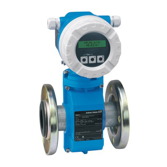
Proline Promag 10 Identification Identification Device designation The flowmeter system consists of the following components: • Promag 10 transmitter • Promag W, Promag P or Promag H sensor In the compact version, the transmitter and sensor form a mechanical unit; in the remote version they are mounted separate from one another. -
Page 8: Nameplate Of The Sensor
Identification Proline Promag 10 2.1.2 Nameplate of the sensor PROMAG P XXP1H-XXXXXXXXXXXX Order Code: 12345678901 Ser.No.: ABCDEFGHJKLMNPQRST TAG No.: 0.5328/ 5 - 0,5% CAL K-factor: DN100 DIN EN PN16 –40 °C ...+130°C/–40 ...+265°F °F PTFE Materials: 1.4435/316L EPD/MSÜ, R/B Electrodes: -20°C (-4°F)<Tamb<+60°C (+140°F) -
Page 9: Certificates And Approvals
Laboratory Procedures” and with the EMC requirements of EN 61326/A1 (IEC 1326). The measuring system described in these Operating Instructions thus complies with the statutory requirements of the EC Directives. Endress+Hauser confirms successful testing of the device by affixing to it the CE mark. -
Page 10: Proline Promag
Installation Proline Promag 10 Installation Incoming acceptance, transport, storage 3.1.1 Incoming acceptance On receipt of the goods, check the following points: • Check the packaging and the contents for damage. • Check the shipment, make sure nothing is missing and that the scope of supply matches your order. -
Page 11: Storage
Proline Promag 10 Installation Transporting flanged devices (DN > 300) Use only the metal eyes on the flanges for transporting the device, lifting it and positioning the sensor in the piping. " Caution! Do not attempt to lift the sensor with the tines of a fork-lift truck beneath the metal casing. -
Page 12: Installation Conditions
Installation Proline Promag 10 Installation conditions 3.2.1 Dimensions The dimensions and lengths of the sensor and transmitter can be found in the “Technical Information” document for the device in question. This can be downloaded as a PDF file from www.endress.com. A list of the “Technical Information” documents available is provided in Section “Documentation”... - Page 13 Proline Promag 10 Installation Partially filled pipes Partially filled pipes with gradients necessitate a drain-type configuration. The empty pipe detection function (EPD → Page 58) provides additional security in detecting empty or partially filled pipes. " Caution! Risk of solids accumulating! Do not install the sensor at the lowest point in the drain. It is advisable to install a cleaning valve.
-
Page 14: Orientation
Installation Proline Promag 10 3.2.3 Orientation An optimum orientation helps avoid gas and air accumulations and deposits in the measuring tube. However, Promag also offers the additional function of empty pipe detection for detecting partially filled measuring tubes or if outgassing fluids or fluctuating operating pressures are present. -
Page 15: Vibrations
Proline Promag 10 Installation Inlet and outlet run If possible, install the sensor well clear of assemblies such as valves, T-pieces, elbows, etc. Note the following inlet and outlet runs to comply with measuring accuracy specifications: • Inlet run: ≥ 5 x DN •... -
Page 16: Foundations, Supports
Installation Proline Promag 10 3.2.5 Foundations, supports For nominal diameters DN ≥ 350, mount the sensor on a foundation of adequate load-bearing strength. " Caution! Risk of damage! Do not support the weight of the sensor at the metal casing. The casing would buckle and damage the internal magnetic coils. -
Page 17: Nominal Diameter And Flow Rate
Proline Promag 10 Installation 3.2.7 Nominal diameter and flow rate The diameter of the pipe and the flow rate determine the nominal diameter of the sensor. The optimum flow velocity is between 2 and 3 m/s. The velocity of flow (v), moreover, has to be matched to the physical properties of the fluid: •... - Page 18 Installation Proline Promag 10 US units Recommended flow rate Diameter Promag W Promag P Promag H Min./max. full scale value Min./max. full scale value Min./max. full scale value (v ≈ 0.3 or 10 m/s) (v ≈ 0.3 or 10 m/s) (v ≈...
-
Page 19: Length Of Connecting Cable
Proline Promag 10 Installation 3.2.8 Length of connecting cable When mounting the remote version, please note the following to achieve correct measuring results: • Fix cable run or lay in armoured conduit. Cable movements can falsify the measuring signal especially in the case of low fluid conductivities. -
Page 20: Installation
Installation Proline Promag 10 Installation 3.3.1 Installing Promag W sensor Note! Bolts, nuts, seals, etc. are not included in the scope of supply and must be supplied by the customer. The sensor is designed for installation between the pipe flanges: •... - Page 21 Ground disks must also be mounted between the sensor and the pipe flange for potential equalisation under certain application conditions, e.g. in the case of lined or ungrounded piping (→ Page 40). Ground disks can be ordered as separate accessories from Endress+Hauser (→ Page 60).
- Page 22 Installation Proline Promag 10 Tightening torques for Promag W for EN (DIN) Diameter EN (DIN) Max. tightening torque [Nm] [mm] Pressure rating Screws Hard rubber Polyurethane [bar] PN 40 4 x M 12 PN 40 4 x M 16 PN 40...
- Page 23 Proline Promag 10 Installation Diameter EN (DIN) Max. tightening torque [Nm] [mm] Pressure rating Screws Hard rubber Polyurethane [bar] 1200 PN 16 32 x M 45 1400 PN 6 36 x M 33 1400 PN 10 36 x M 39...
- Page 24 Installation Proline Promag 10 Diameter Max. tightening torque [Nm] [mm] Pressure rating Screws Hard rubber Polyurethane 8 x M 16 8 x M 16 8 x M 20 8 x M 16 8 x M 20 8 x M 20...
-
Page 25: Installing Promag P Sensor
Proline Promag 10 Installation Tightening torques for Promag W for AS 4087 Diameter AS 4087 Max. tightening torque [Nm] [mm] Pressure rating Screws Hard rubber Cl.14 4 x M 16 100 * Cl.14 8 x M 16 Cl.14 8 x M 20 Cl.14... - Page 26 Ground disks must also be mounted between the sensor and the pipe flange for potential equalisation under certain application conditions, e.g. in the case of lined or ungrounded piping (→ Page 40). Ground disks can be ordered as separate accessories from Endress+Hauser (→ Page 60).
- Page 27 Proline Promag 10 Installation Tightening torques for Promag P for EN (DIN) Diameter EN (DIN) Max. tightening torque [Nm] [mm] Nominal Screws PTFE pressure [bar] PN 40 4 x M 12 PN 40 4 x M 16 PN 40 4 x M 16...
- Page 28 Installation Proline Promag 10 Tightening torques for Promag P for ANSI ANSI Screws Max. tightening torque [Nm] Diameter Pressure rating [mm] [inch] [lbs] PTFE 1" Class 150 4 x 1/2" 1" Class 300 4 x 5/8" 1 1/2" Class 150 4 x 1/2"...
-
Page 29: Installing Promag H Sensor
Depending on the application and piping length, the sensor may have to be supported or additionally secured. The measured value sensor has to be secured if using plastic process connections. An appropriate wall mounting kit can be ordered separately as an accessory from Endress+Hauser (→ Page 60). -
Page 30: Rotating The Transmitter Housing
Installation Proline Promag 10 Welding the transmitter into the piping (weld sockets) " Caution! Danger of destroying the meter electronics! Make sure that the welding system is not grounded through the sensor or transmitter. Secure the sensor in the piping with a few weld points. A suitable welding aid can be ordered separately as an accessory →... -
Page 31: Rotating The Local Display
Proline Promag 10 Installation 3.3.6 Rotating the local display Unscrew cover of the electronics compartment from the transmitter housing. Remove the display module from the transmitter retainer rails. Turn the display to the desired position (max. 4 x 45° in each direction). -
Page 32: Post-Installation Check
Installation Proline Promag 10 Post-installation check Perform the following checks after installing the measuring device in the pipe: Device condition and specifications Notes Is the device damaged (visual inspection)? → Page 76 ff. Does the device correspond to specifications at the measuring point, including process temperature and pressure, ambient temperature, min. -
Page 33: Wiring
Proline Promag 10 Wiring Wiring Warning! When using remote versions, only sensors and transmitters with the same serial number can be connected up. Measuring errors can occur if the devices are not connected in this way. Connecting the remote version 4.1.1... - Page 34 Wiring Proline Promag 10 Electrode circuit Pipe Meas.signal Coil circuit 4 37 36 42 41 n.c. n.c. n.c. 4 37 42 41 A0003193-en Fig. 25: Connecting the remote version Promag W/P Wall-mount housing connection compartment Sensor connection housing cover Signal cable Coil current cable n.c.
- Page 35 Proline Promag 10 Wiring Cable termination for remote version Promag W / Promag P Terminate the signal and coil current cables as shown in the illustrations below (Detail A). Provide the fine-wire cores with wire end ferrules (Detail B: m = red wire end ferrules, ∅ 1.0 mm; n = white wire end ferrules, ∅ 0.5 mm).
- Page 36 Wiring Proline Promag 10 Cable termination for remote version Promag H Terminate the signal and coil current cables as shown in the illustrations below (Detail A). Provide the fine-wire cores with wire end ferrules (Detail B: m = red wire end ferrules, ∅ 1.0 mm; n = white wire end ferrules, ∅ 0.5 mm).
-
Page 37: Cable Specifications
Proline Promag 10 Wiring 4.1.2 Cable specifications Coil cable PVC cable with common, braided copper shield (∅ ∼ 7 mm) • 2 x 0.75 mm • Conductor resistance: ≤ 37 Ω/km • Capacitance core/core, shield grounded: ≤ 120 pF/m • Operating temperature: –20...+80 °C •... -
Page 38: Connecting The Measuring Unit
Wiring Proline Promag 10 Connecting the measuring unit 4.2.1 Transmitter Warning! • Risk of electric shock! Switch off the power supply before opening the device. Do not install or wire the device while it is connected to the power supply. Failure to comply with this precaution can result in irreparable damage to the electronics. -
Page 39: Terminal Assignment
Proline Promag 10 Wiring 4.2.2 Terminal assignment Terminal No. (wiring diagram → Page 38) 24 (+) 25 (–) 26 (+) 27 (–) 1 (L1/L+) 2 (N/L–) Pulse output HART current output Power supply • Galvanically isolated • Galvanically isolated • 85...250 V AC / 45...65 Hz •... -
Page 40: Potential Equalisation
Wiring Proline Promag 10 Potential equalisation Warning! The measuring system must be included in the potential equalisation. 4.3.1 Standard Perfect measurement can only be guaranteed if the fluid and sensor are on the same electric potential. Most sensors have a built-in reference electrode as standard which guarantees the necessary connection. -
Page 41: Special Cases
Note! The ground cable required for the flange-to-flange connection can be ordered separately from Endress+Hauser as an accessory → Page 60: • DN ≤ 300: the ground cable is mounted directly on the conductive flange coating with the flange screws. - Page 42 Wiring Proline Promag 10 Plastic pipelines or pipelines with insulating lining Normally, potential equalisation takes place via the reference electrodes in the measuring tube. However, in exceptional circumstances, large equalising currents can flow via the reference electrodes due to the grounding concept of a plant. This can destroy the sensor due to the electrochemical reduction of the electrodes, for example.
-
Page 43: Degree Of Protection
Caution! The screws on the sensor housing may not be loosened as otherwise the degree of protection guaranteed by Endress+Hauser cannot be ensured. Note! The Promag W and Promag P sensors are also optionally available in IP 68 degree of protection (constantly under water to 3 m depth). -
Page 44: Post-Connection Check
Wiring Proline Promag 10 Post-connection check Perform the following checks after completing electrical installation of the measuring device: Device condition and specifications Notes Are cables or the device damaged (visual inspection)? Electrical connection Notes Does the supply voltage match the specifications on the nameplate? •... -
Page 45: Operation
Proline Promag 10 Operation Operation Display and operating elements The local display enables you to read important parameters directly at the measuring point and also configure the device via the function matrix. The display consists of two lines; this is where measured values and/or status variables (partially filled pipe, etc.) are displayed. -
Page 46: Brief Guide To The Function Matrix
Operation Proline Promag 10 Brief guide to the function matrix Note! • Please refer to the general notes on → Page 47. • Function matrix overview → Page 85 • Detailed description of all functions → Page 86 ff. The function matrix is a two-level construct: the function groups form one level and the groups' functions the other. -
Page 47: General Notes
• If programming is disabled and the P operating elements are pressed in any function, a prompt for the code automatically appears on the display. • If “0” is specified as the private code, programming is always enabled. • The Endress+Hauser service organisation can be of assistance if you mislay your personal code. " Caution! Changing certain parameters such as all sensor characteristics, for example, influences numerous functions of the entire measuring device, particularly measuring accuracy. -
Page 48: Error Message Display
Operation Proline Promag 10 Error message display 5.3.1 Type of error Errors which occur during commissioning or measuring operation are displayed immediately. If two or more system or process errors occur, the error with the highest priority is always the one shown on the display. -
Page 49: Communication
Proline Promag 10 Operation Communication In addition to local operation, the measuring device can also be configured and measured values obtained by means of the HART protocol. Digital communication takes place using the 4–20 mA current output HART → Page 39. -
Page 50: Device Variables
Operation Proline Promag 10 “SIMATIC PDM” operating program (Siemens) SIMATIC PDM is a standardised, manufacturer-independent tool for the operation, configuration, maintenance and diagnosis of intelligent field devices. “AMS” operating program (Emerson Process Management) AMS (Asset Management Solutions): program for operating and configuring devices. -
Page 51: Hart Commands
Proline Promag 10 Operation 5.4.4 Universal / common practice HART commands The following table contains all the universal commands supported by the device. Command No. Command data Response data HART command / Access type (numeric data in decimal form) (numeric data in decimal form) - Page 52 Operation Proline Promag 10 Command No. Command data Response data HART command / Access type (numeric data in decimal form) (numeric data in decimal form) Set HART shortform address Byte 0: desired address (0...15) Byte 0: active address Access type = Write...
- Page 53 Proline Promag 10 Operation Command No. Command data Response data HART command / Access type (numeric data in decimal form) (numeric data in decimal form) Write user message You can save any 32-character long text in the device Displays the current user message in the device:...
- Page 54 Operation Proline Promag 10 Command No. Command data Response data HART command / Access type (numeric data in decimal form) (numeric data in decimal form) Write unit of the primary process Specify the unit of the primary process variable. Only...
-
Page 55: Device Status/Error Messages
Proline Promag 10 Operation 5.4.5 Device status/error messages You can read the extended device status, in this case, current error messages, via command “48”. The command delivers bit-encoded information (see table below). Note! • For detailed information on the device status messages and error messages, and how they are rectified →... -
Page 56: Commissioning
Commissioning Proline Promag 10 Commissioning Function check Make sure that all final checks have been completed before you commission your measuring point: • “Post-installation check” checklist → Page 32 • “Post-connection check” checklist → Page 44 Switching on the measuring device Once the post-connection checks have been successfully completed, it is time to switch on the supply voltage. -
Page 57: New Electronics Board
Proline Promag 10 Commissioning Commissioning after installing a new electronics board After start-up, the device checks whether a serial number is available. If this is not the case, the following setup is started. Installing a new electronics board → Page 68. -
Page 58: Empty-Pipe/Full-Pipe Adjustment
Commissioning Proline Promag 10 Empty-pipe/full-pipe adjustment Flow cannot be measured correctly unless the measuring tube is completely full. This status can be permanently monitored using the Empty Pipe Detection: EPD = Empty pipe detection (with the help of an EPD electrode). -
Page 59: Maintenance
Proline Promag 10 Maintenance Maintenance No special maintenance work is required. Exterior cleaning When cleaning the exterior of measuring devices, always use cleaning agents that do not attack the surface of the housing and the seals. Seals The seals of the Promag H sensor should be replaced periodically, especially if moulded seals are... -
Page 60: Accessories
Accessories Proline Promag 10 Accessories Various accessories, which can be ordered separately from Endress+Hauser, are available for the transmitter and the sensor. Your Endress+Hauser service organisation can provide detailed information on the order code in question. Accessory Description Order code Promag 10 transmitter Transmitter for replacement or for stock. - Page 61 • Measuring device configuration • Service functions • Visualisation of process data • Trouble-shooting • Controlling the “Fieldcheck” tester/simulator Contact your Endress+Hauser representative for more information. Fieldcheck Tester/simulator for testing flowmeters in the field. 50098801 When used in conjunction with the “ToF Tool - Fieldtool Package”...
-
Page 62: Trouble-Shooting
Trouble-shooting Proline Promag 10 Trouble-shooting Trouble-shooting instructions Always start trouble-shooting with the checklist below, if faults occur after commissioning or during operation. This takes you directly (via various queries) to the cause of the problem and the appropriate remedial measures. -
Page 63: System Error Messages
Proline Promag 10 Trouble-shooting System error messages Serious system errors are always recognised by the device as “Fault messages” and are indicated with a lightning flash ($) on the display! Fault messages have a direct effect on the outputs. Simulations and positive zero return, on the other hand, are only classed and displayed as notice messages. - Page 64 Trouble-shooting Proline Promag 10 Type Error message / No. Cause Remedy / spare part CURRENT RANGE Current output: – Change the upper or lower limit setting, # 351 The current flow is outside the set as applicable. range. – Increase or reduce flow...
-
Page 65: Process Error Messages
The following options are available for tackling problems of this nature: some other fault not described Request the services of an Endress+Hauser service technician above has occurred. If you contact our service organisation to have a service technician sent out, please... -
Page 66: Response Of Outputs To Errors
Trouble-shooting Proline Promag 10 Response of outputs to errors Note! The response of the totalizer, current output, pulse output and status output is defined in the FAILSAFE MODE function (→ Page 104). You can use positive zero return to set the signals of the current, pulse and status outputs to their fallback value, for example when operation has to be interrupted while a pipe is being cleaned. -
Page 67: Spare Parts
Note! You can order spare parts directly from your Endress+Hauser service organisation by quoting the serial number printed on the transmitter nameplate → Page 7. Spare parts are shipped as sets comprising the following parts: •... -
Page 68: Removing And Installing Electronics Boards
" Caution! Use only genuine Endress+Hauser parts. Note! Commissioning a new electronics board: → Page 57 Switch off power supply. Unscrew cover of the electronics compartment from the transmitter housing. - Page 69 Proline Promag 10 Trouble-shooting F06-10xxxxxx-03-06-06-xx-001 Fig. 41: Field housing: removing and installing electronics boards Local display Latches Connector of the electrode signal cable Connector of the coil current cable Connector for the power supply Connector for current output and pulse/status output...
-
Page 70: Replacing The Device Fuse
– Power supply 85...250 V DC → 1 A slow-blow / 250 V TR5 Installation is the reverse of the removal procedure. " Caution! Use only genuine Endress+Hauser parts. F06-10xxxxxx-03-xx-06-xx-000 Fig. 42: Replacing the device fuse on the electronics board... -
Page 71: Software History
Proline Promag 10 Trouble-shooting 9.11 Software history Date Software Software modification Operating version Instructions 10.2004 V 1.02.00 Software modification/extension 50104787 / 05.05 Function: SELF CHECKING 09.2004 V 1.01.01 Software modification 50104787 / 04.03 Extension of nominal diameter range 06.2004 V 1.01.00 Software extension 50104787 / 04.03... -
Page 72: Technical Data
Technical data Proline Promag 10 Technical data 10.1 Technical data at a glance 10.1.1 Application • Measuring the flow rate of fluids in closed piping systems. • A minimum conductivity of ≥ 50 µS/cm is required for measuring. • Applications in measuring, control and regulation technology. -
Page 73: Power Supply
Proline Promag 10 Technical data 10.1.4 Output Output signal Current output • Galvanically isolated • Full scale value adjustable • Temperature coefficient: typ. 2 µA/°C, resolution: 1.5 µA < 700 Ω (for HART: RL ≥ 250 Ω) • Active: 4...20 mA, R Pulse/status output: •... -
Page 74: Performance Characteristics
Technical data Proline Promag 10 10.1.6 Performance characteristics Reference operating As per DIN EN 29104 and VDI/VDE 2641: conditions • Fluid temperature: +28 C ± 2 K • Ambient temperature: +22 C ± 2 K • Warm-up period: 30 minutes Installation: •... -
Page 75: Operating Conditions: Environment
Proline Promag 10 Technical data 10.1.8 Operating conditions: Environment Ambient temperature range • Transmitter: –20...+60 °C • Sensor: – For carbon steel flange material (Promag W, P): –10...+60 °C – For stainless steel flange material (Promag H): –20...+60 °C "... -
Page 76: Operating Conditions: Process
Technical data Proline Promag 10 10.1.9 Operating conditions: Process Medium temperature range The permitted temperature depends on the measuring tube lining Promag W • 0...+80 °C for hard rubber (DN 65...2000) • 20...+50 °C for polyurethane (DN 25...1000) Promag P •... - Page 77 Proline Promag 10 Technical data Medium pressure range Promag W • EN 1092-1 (DIN 2501) – PN 6 (DN 1200...2000) – PN 10 (DN 200...2000) – PN 16 (DN 65...2000) – PN 25 (DN 200...1000) – PN 40 (DN 25...150) •...
-
Page 78: Mechanical Construction
Technical data Proline Promag 10 Pressure tightness Promag W Measuring tube Pressure tightness, measuring tube lining nominal diameter lining Limit values for abs. pressure [mbar] at various fluid temperatures [mm] [inch] 25 °C 50 °C 80 °C 100 °C 130 °C 150 °C... - Page 79 Proline Promag 10 Technical data Weight Promag W weight data in kg Diameter Compact version Remote version (without cable) Sensor Trans- mitter [mm] [inch] EN (DIN)/ ANSI/ EN (DIN) / ANSI/ AWWA AWWA 1" 1 1/4" – – 1 1/2"...
- Page 80 Technical data Proline Promag 10 Promag P weight data in kg Diameter Compact version Remote version (without cable) Sensor Trans- mitter [mm] [inch] EN (DIN)/ ANSI/ EN (DIN)/ ANSI/ AWWA AWWA 1" 1 1/4" – – 1 1/2" 2" 2 1/2"...
- Page 81 Proline Promag 10 Technical data Material Promag W and P • Transmitter housing: powder-coated die-cast aluminium • Sensor housing – DN 25...300: powder-coated die-cast aluminium – DN 350...2000: coated steel (Amerlock 400) • Measuring tube – DN < 350: stainless steel 1.4301 or 1.4306/304L Flange material with Al/Zn protective coating –...
-
Page 82: Human Interface
Technical data Proline Promag 10 Process connection Promag W and P Flange connections: • EN 1092-1 (DIN 2501), DN 65 PN 16 and DN 600 PN 16 exclusively to EN 1092-1 • ANSI • AWWA (only Promag W) • JIS •... -
Page 83: Ordering Information
10.1.12 Certificates and approvals Ex approvals Information about currently available Ex versions (ATEX, FM, CSA, etc.) can be supplied by your Endress+Hauser Sales Centre on request. All explosion protection data are given in a separate documentation which is available upon request. Sanitary compatibility Promag W and P •... -
Page 84: Measuring Tube Specifications
• Technical Information Promag 10 W (TI 093D/06/en) • Technical Information Promag 10 P (TI 094D/06/en) • Technical Information Promag 10 H (TI 095D/06/en) You can also download these documents as PDF files from Endress+Hauser's Internet site → www.endress.com 10.3... -
Page 85: Appendix
Proline Promag 10 Appendix Appendix 11.1 Illustration of the function matrix Endress+Hauser... -
Page 86: Group System Units
Appendix Proline Promag 10 11.2 Group SYSTEM UNITS Functional description SYSTEM UNITS Use this function group to select the unit required and displayed for the measured variable. UNIT VOLUME FLOW Use this function to select the unit required and displayed for the volume flow. -
Page 87: Group Operation
HOME position. • You can also disable programming in this function by entering any number (other than the defined private code). • The Endress+Hauser service organisation can be of assistance if you mislay your personal code. DEFINE PRIVATE Use this function to enter a personal code to enable programming. -
Page 88: Group User Interface
Appendix Proline Promag 10 11.4 Group USER INTERFACE Functional description USER INTERFACE FORMAT Use this function to define the maximum number of places after the decimal point displayed for the reading in the main line. Options: XXXXX. XXXX.X XXX.XX XX.XXX X.XXXX... -
Page 89: Group Totalizer
Proline Promag 10 Appendix 11.5 Group TOTALIZER Functional description TOTALIZER The total for the totalizer's measured variable aggregated since measuring commenced appears on the display. This value can be positive or negative, depending on: • Flow direction and/or • Setting in the MEASURING MODE function → Page 100 Display: Max. -
Page 90: Group Current Output
Appendix Proline Promag 10 11.6 Group CURRENT OUTPUT Functional description CURRENT OUTPUT Note! The functions of the CURRENT OUTPUT group are only available if the “0” value was entered in the BUS ADDRESS function → Page 97. CURRENT RANGE Use this function to specify the current range. You can configure the current output either in accordance with the NAMUR recommendation (max. - Page 91 Proline Promag 10 Appendix Functional description CURRENT OUTPUT VALUE 20 mA Use this function to assign the 20 mA current a full scale value. Positive and negative values are permitted. The required measuring range is defined by defining the VALUE 20 mA .
-
Page 92: Group Pulse/Status Output
Appendix Proline Promag 10 11.7 Group PULSE/STATUS OUTPUT Functional description PULSE/STATUS OUTPUT OPERATING MODE Configuration of the output as a pulse or status output. The functions available in this function group vary, depending on which option you select here. Options:... - Page 93 Proline Promag 10 Appendix Functional description PULSE/STATUS OUTPUT OUTPUT SIGNAL Note! This function is not available unless the PULSE setting was selected in the OPERATING MODE function. Use this function to configure the output in such a way that it matches an external counter, for example.
-
Page 94: Of The Status Output
Appendix Proline Promag 10 Functional description PULSE/STATUS OUTPUT SWITCH-OFF POINT Note! This function is not available unless LIMIT VALUE was selected in the ASSIGN STATUS OUTPUT function. Use this function to assign a value to the switch-off point (status output drops off). -
Page 95: Of The Status Output
Proline Promag 10 Appendix Status output configured for limit value The status output switches as soon as the measured variable undershoots or overshoots a defined switch point. Application: monitoring flow or process-related boundary conditions. A0001235 • A = Maximum safety: →... - Page 96 Appendix Proline Promag 10 Function State Open collector behaviour (Transistor) Fault message System OK conductive XXX.XXX.XX notice message A0001237 (System error or process error) not conductive Fault → Response to error or XXX.XXX.XX Notice → Continuation of measuring A0001239 Empty pipe...
-
Page 97: Group Communication
MANUFACTURER ID Use this function to view the manufacturer ID in decimal numerical format. Display: – Endress+Hauser – 17 (≅ 11 hex) for Endress+Hauser DEVICE ID Use this function to view the device ID in hexadecimal numerical format. Display: 45 hex (≅ 69 dec) for Promag 10... -
Page 98: Group Process Parameter
Appendix Proline Promag 10 11.9 Group PROCESS PARAMETER Functional description PROCESS PARAMETER SWITCH-ON POINT Use this function to enter the switch-on point for low flow cut off. LOW FLOW CUT OFF Low flow cut off is active if the value entered is not equal to 0. The sign of the flow value is highlighted on the display to indicate that low flow cut off is active. - Page 99 Proline Promag 10 Appendix Functional description PROCESS PARAMETER EPD-MODE Notes on empty pipe detection (EPD) (continued) • Flow cannot be measured correctly unless the measuring tube is completely full. This status can be monitored at all times by means of the EPD.
-
Page 100: Group System Parameter
Appendix Proline Promag 10 11.10 Group SYSTEM PARAMETER Functional description SYSTEM PARAMETER INSTALLATION Use this function to reverse the sign of the flow quantity, if necessary. DIRECTION SENSOR Options: FORWARDS (flow as indicated by the arrow) BACKWARDS (flow opposite to direction indicated by the arrow) - Page 101 Proline Promag 10 Appendix Functional description SYSTEM PARAMETER Measuring mode Pulse output (Contd) STANDARD Only flow components of the positive flow direction are output. Components in the opposite direction are not taken into account. SYMMETRY The absolute value of the positive and negative flow components is taken into account.
- Page 102 Appendix Proline Promag 10 Functional description SYSTEM PARAMETER POSITIVE ZERO Use this function to interrupt evaluation of measured variables. RETURN This is necessary when a piping system is being cleaned, for example. This setting acts on all function and outputs of the measuring device.
-
Page 103: Group Sensor Data
Proline Promag 10 Appendix 11.11 Group SENSOR DATA Functional description SENSOR DATA All sensor data (calibration factors, zero point and nominal diameter etc.) are set at the factory. " Caution! Under normal circumstances you should not change the following parameter settings, because changes affect numerous functions of the entire measuring facility in general and the accuracy of the measuring system in particular. -
Page 104: Group Supervision
Appendix Proline Promag 10 11.12 Group SUPERVISION Functional description SUPERVISION FAILSAFE MODE The dictates of safety render it advisable to ensure that the device signal processing assumes a predefined state in the event of a fault. The setting you select here is valid for: •... - Page 105 Proline Promag 10 Appendix Functional description SUPERVISION ALARM DELAY Use this function to define a time span in which the criteria for an error have to be satisfied without interruption before an error or notice message is generated. Depending on the setting and the type of error, this suppression acts on: •...
-
Page 106: Group Simulation System
Appendix Proline Promag 10 11.13 Group SIMULATION SYSTEM Functional description SIMULATION SYSTEM SIMULATION Use this function to set all outputs and the totalizer to their defined failsafe modes, in order FAILSAFE MODE to check whether they respond correctly. During this time, the words “SIMULATION FAILSAFE MODE” appear on the display. -
Page 107: Group Sensor Version
Proline Promag 10 Appendix 11.14 Group SENSOR VERSION Functional description SENSOR VERSION SERIAL NUMBER Use this function to view the serial number of the sensor. SENSOR TYPE Use this function to view the sensor type. 11.15 Group AMPLIFIER VERSION Functional description AMPLIFIER VERSION SOFTWARE REVISION Use this function to view the software revision number of the electronics board. -
Page 108: Factory Settings
Appendix Proline Promag 10 11.16 Factory settings 11.16.1 SI units (not for USA and Canada) Low flow cut off, full scale value, pulse value, totalizer Diameter Low flow cut off Current output full Pulse value Totalizer scale value [mm] [inch] (approx. - Page 109 Proline Promag 10 Appendix Language Country Language Belgium English Denmark English Germany Deutsch England English Finland English France Francais Holland English Hong Kong English International Instruments English Italy Italiano Japan English Malaysia English Norway English Austria Deutsch Sweden English Switzerland...
- Page 110 Appendix Proline Promag 10 11.16.2 US units (only for USA and Canada) Low flow cut off, full scale value, pulse value, totalizer Diameter Low flow cut off Current output full Pulse value Totalizer scale value [inch] [mm] (approx. (approx. v = 2.5 m/s) (approx.
-
Page 111: Index
Proline Promag 10 Index Index ACCESS CODE....... . . 87 Electrical connection . - Page 112 Adapters ........16 ToF Tool - Fieldtool Package (Endress+Hauser) ..49 Dimensions .
- Page 113 Proline Promag 10 Index Promag P SYSTEM DAMPING ......102 Ground cable....... . 26 System error (definition) .
- Page 114 Index Proline Promag 10 Endress+Hauser...
- Page 116 www.endress.com/worldwide BA082D/24/ae/09.05 50104788 FM+SGML6.0 ProMoDo...