Endress+Hauser Levelflex FMP51 Operating Instructions Manual
Guided level-radar level and interface measurement in liquids
Hide thumbs
Also See for Levelflex FMP51:
- Operating instructions manual (254 pages) ,
- Technical information (132 pages) ,
- Brief operating instructions (56 pages)

Related Manuals for Endress+Hauser Levelflex FMP51


Summary of Contents for Endress+Hauser Levelflex FMP51
- Page 1 Operating Instructions Levelflex FMP51, FMP52, FMP54 Guided Level-Radar Level and interface measurement in liquids BA01052F/00/EN/02.12 71206442 Valid as of version 01.00.zz...
-
Page 3: Table Of Contents
Levelflex FMP51, FMP52, FMP54 Table of contents Table of contents 6.1.6 FMP54: Dimensions of process connection Important document information ..6 and probe ..... . . 33 About this document . - Page 4 ... . 104 Index tables of Endress+Hauser parameters ..79 11.9 Configuration management ....104 9.6.1 Setup Transducer Block .
- Page 5 Levelflex FMP51, FMP52, FMP54 Table of contents Maintenance ..... 124 14.1 Exterior cleaning ..... .
-
Page 6: Important Document Information
The document types listed are available: • On the CD supplied with the device • In the Download Area of the Endress+Hauser Internet site: www.endress.com ® Download 1.1.3 Safety Instructions (XA) for Levelflex FMP51, FMP52, FMP54 Depending on the approval, the following Safety Instructions (XA) are supplied with the instrument. -
Page 7: Document Conventions
Levelflex FMP51, FMP52, FMP54 Important document information 51 52 54 Feature Approval Safety Instructions Safety Instructions HART PROFIBUS FOUNDATION Fieldbus CSA C/US DIP Cl.I,II Div.1 Gr.E-G XA00529F XA00570F CSA C/US IS Cl.I,II,III Div.1 Gr.A-G, NI Cl.1 Div.2, Ex ia XA00530F XA00571F CSA C/US XP Cl.I,II,III Div.1 Gr.A-G, NI Cl.1 Div.2, Ex d... -
Page 8: Electrical Symbols
Important document information Levelflex FMP51, FMP52, FMP54 Symbol Meaning CAUTION CAUTION This symbol alerts you to a dangerous situation. Failure to avoid this situation can result in minor or medium injury. A0011191-EN NOTICE NOTICE This symbol contains information on procedures and other facts which do not result in personal injury. -
Page 9: Symbols In Graphics
Levelflex FMP51, FMP52, FMP54 Important document information Symbol Meaning Indicates additional information. A0011193 Reference to documentation Refers to the corresponding device documentation. A0011194 Reference to page Refers to the corresponding page number. A0011195 Reference to graphic Refers to the corresponding graphic number and page number. -
Page 10: Basic Safety Instructions
The manufacturer is not liable for damage caused by improper or non-designated use. Verification for borderline cases: For special measured materials and cleaning agents, Endress+Hauser is glad to provide ► assistance in verifying the corrosion resistance of wetted materials, but does not accept any warranty or liability. -
Page 11: Operational Safety
It fulfills general safety requirements and legal requirements. It also conforms to the EC directives listed in the device-specific EC declaration of conformity. Endress+Hauser confirms this fact by applying the CE mark. Endress+Hauser... -
Page 12: Product Description
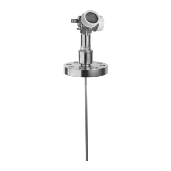
Product description Levelflex FMP51, FMP52, FMP54 Product description Product design 3.1.1 Compact device Levelflex A0012399 Design of the Levelflex å 1 Electronics housing Process connection (here as an example: flange) Rope probe End-of-probe weight Rod probe Coax probe Endress+Hauser... -
Page 13: Electronics Housing
Levelflex FMP51, FMP52, FMP54 Product description 3.1.2 Electronics housing A0012422 Design of the electronics housing å 2 Electronics compartment cover Display module Main electronics module Cable glands (1 or 2, depending on instrument version) Nameplate I/O electronics module Terminals (pluggable spring terminals) - Page 14 Product description Levelflex FMP51, FMP52, FMP54 US Patents EP Patents 6.481.276 6.512.358 1 301 914 6.559.657 1 020 735 6.640.628 6.691.570 6.847.214 7.441.454 7.477.059 1 389 337 7.965.087 Endress+Hauser...
-
Page 15: Incoming Acceptance And Product
Levelflex FMP51, FMP52, FMP54 Incoming acceptance and product identification Incoming acceptance and product identification Incoming acceptance DELIVERY NOTE 1 = 2 A0013696 A0016870 Is the order code on the delivery note (1) identical to the order code on the product sticker (2)? -
Page 16: Product Identification
Are the CD-ROMs (product documentation, operating tool) and documentation present? If required (see nameplate): Are the Safety Instructions (XA) present? If one of the conditions does not comply, contact your Endress+Hauser distributor. Product identification The following options are available for identification of the measuring device: •... -
Page 17: Nameplate
Levelflex FMP51, FMP52, FMP54 Incoming acceptance and product identification 4.2.1 Nameplate 92 (3.62) Order code: Ser. no.: Ext. ord. cd.: LN = MWP: Lref = Mat.: DeviceID: Dev.Rev.: if modification see sep. label Date: mm (in) 19 18 17 16... - Page 18 Incoming acceptance and product identification Levelflex FMP51, FMP52, FMP54 Approval: 51 52 54 ATEX II 1/2G Ex d(ia) IIC T6 ATEX II 1/3G Ex ic(ia) IIC T6 ATEX II 1 D Ex tD IIIC IP6x ATEX II 1/2 D Ex tD IIIC IP6x...
- Page 19 Levelflex FMP51, FMP52, FMP54 Incoming acceptance and product identification Power Supply, Output 51 52 54 2-wire; 4-20mA HART 2-wire; 4-20mA HART, 4-20mA 2-wire; FOUNDATION Fieldbus, switch output 2-wire. PROFIBUS PA, switch output 4-wire 90-253VAC; 4-20mA HART 4-wire 10,4-48VDC; 4-20mA HART Special version, TSP-no.
- Page 20 Incoming acceptance and product identification Levelflex FMP51, FMP52, FMP54 Probe: 51 52 54 ..inch, rod 0.63in 316L, 40 inch divisible ..mm, rod 16mm PFA>316L ..inch, rod 0.63in PFA>316L ..mm, rope 4mm 316 ..inch, rope 1/6 316 ..
- Page 21 Levelflex FMP51, FMP52, FMP54 Incoming acceptance and product identification Process connection: 51 52 54 8 150lbs RF, 316/316L flange ANSI B16.5 (CRN) 4 600lbs RF, 316/316L flange ANSI B16.5 (CRN) 1-1/2 300lbs RF, 316/316L flange ANSI B16.5 (CRN) AQK 1-1/2 300lbs, PTFE>316/316L flange ANSI B16.5 AQM 1-1/2 300lbs, AlloyC>316/316L flange ANSI B16.5 (CRN)
- Page 22 Incoming acceptance and product identification Levelflex FMP51, FMP52, FMP54 Process connection: 51 52 54 Thread ISO228 G1-1/2, 316L (CRN) Thread ISO228 G1-1/2, 200bar, 316L (CRN) Thread ISO228 G1-1/2, 400bar, 316L (CRN) 10K 40 RF, 316L flange JIS B2220 10K 40, PTFE>316L flange JIS B2220 10K 50 RF, 316L flange JIS B2220 10K 50, PTFE>316L flange JIS B2220...
- Page 23 Levelflex FMP51, FMP52, FMP54 Incoming acceptance and product identification Additional Operation Language: 51 52 54 English German French Spanish Italian Dutch Portuguese Polish Russian Chinese simplified Japanese Korean Czech Application Package: (Multiple options can be selected) 51 52 54 Interface measurement...
- Page 24 Incoming acceptance and product identification Levelflex FMP51, FMP52, FMP54 Test, Certificate: (Multiple options can be selected) 51 52 54 3.1 Material certificate+PMI test (XRF) internalprocedure, wetted metallic parts, EN10204-3.1 inspection certificate Liquid penetrant test AD2000-HP5-3(PT), wetted/pressure retaining metallic parts, inspection...
- Page 25 Levelflex FMP51, FMP52, FMP54 Incoming acceptance and product identification Tagging: (Multiple options can be selected) 51 52 54 Tagging (TAG), see additional spec. Bus address, see additional spec. Endress+Hauser...
-
Page 26: Storage, Transport
Storage, Transport Levelflex FMP51, FMP52, FMP54 Storage, Transport Storage conditions • Permitted storage temperature: –40 to +80 °C (–40 to +176 °F) • Use the original packaging. Transport product to the measuring point WARNING Risk of injury if the hosuing breaks away Transport the measuring device to the measuring point in its original packaging or at the ►... -
Page 27: Mounting
Levelflex FMP51, FMP52, FMP54 Mounting Mounting Mounting dimensions 6.1.1 Dimensions of the electronics housing 90 (3.54) 78 (3.07) A0015132 Housing GT18 (316L); Dimensions in mm (in) å 4 78 (3.07) 90 (3.54) A0015133 Housing GT19 (Plastics PBT); Dimensions in mm (in) å... -
Page 28: Dimensions Of The Mounting Bracket
Mounting Levelflex FMP51, FMP52, FMP54 6.1.2 Dimensions of the mounting bracket 122 (4.8) 140 (5.5) 158 (6.2) 175 (6.9) Ø 42 ... 60 mm (inch) (1-1/4 ... 2) A0014793 Mounting bracket for the electronics housing å 7 Wall mounting Pipe mounting For the Sensor remote device version (see feature 060 of the product structure), the mounting bracket is part of the delivery. -
Page 29: Fmp51: Dimensions Of Process Connection (G¾,Npt¾) And Probe
Levelflex FMP51, FMP52, FMP54 Mounting 6.1.3 FMP51: Dimensions of process connection (G¾,NPT¾) and probe (4.8) = 100 (4) ø82.5 ø59.35 (ø3.25) (ø2.34) SW36 AF36 ¾ NPT¾ ø10 (0.4) ø4 ø4 ø8 ø22 (ø0.16) (ø0.16) (ø0.31) (ø .87) 2 (0.08) ø29 (ø1.14) ø22... -
Page 30: Fmp51: Dimensions Of Process Connection (G1½,Npt1½,Flange) And Probe
Mounting Levelflex FMP51, FMP52, FMP54 6.1.4 FMP51: Dimensions of process connection (G1½,NPT1½,flange) and probe (4.8) = 100 (4) ø59.35 ø59.35 ø59.35 (ø2.34) (ø2.34) (ø2.34) ø82.5 SW55 SW55 (ø3.25) AF55 AF55 ½ ½ SW10 SW14 AF10 AF14 ø10 (0.4) SW10 AF10 ø16... - Page 31 Levelflex FMP51, FMP52, FMP54 Mounting Coax probe; 316L (Feature 060) LN Length of probe Reference point of the measurement Æ95 mm (3.74 in) PEEK 7 mm (0.28 in) 10 mm (0.39 in) 37 mm (1.46 in) 110 mm (4.33 in) Æ45 mm (1.77 in)
-
Page 32: Fmp52: Dimensions Of Process Connection And Probe
Mounting Levelflex FMP51, FMP52, FMP54 6.1.5 FMP52: Dimensions of process connection and probe (4.8) = 100 (4) ø82.5 (ø3.25) ø59.8 (ø2.35) ø68.5 ø59.8 ø63.9 ø90.89 (ø 2.7) (ø2.35) (ø 2.52) (ø 3.58) ø16 ø16 ø16 ø16 ø16 (ø 0.63) (ø... -
Page 33: Fmp54: Dimensions Of Process Connection And Probe
Levelflex FMP51, FMP52, FMP54 Mounting 6.1.6 FMP54: Dimensions of process connection and probe (4.8) SW60 SW60 AF60 AF60 ø82.5 (ø3.25) ø90 ø90 ø90 (ø3.54) ø90 (ø3.54) (ø3.54) (ø3.54) SW14 SW14 SW14 SW14 AF14 AF14 AF14 AF14 M40x1 M40x1 M40x1 M40x1 ø16... -
Page 34: Mounting Requirements
Mounting Levelflex FMP51, FMP52, FMP54 Coax probe (Feature 060) LN Length of probe Reference point of the measurement Æ95 mm (3.74 in) PEEK 7 mm (0.28 in) 10 mm (3.94 in) 37 mm (1.46 in) 110 mm (4.33 in) Æ45 mm (1.77 in) 316L 4 mm (0.16 in) -
Page 35: Applications With Restricted Mounting
Levelflex FMP51, FMP52, FMP54 Mounting Additional conditions • When mounting in the open, a weather protection cover (1) may be installed to protect the device against extreme weather conditions. • In metallic vessels: Preferably do not mount the probe in the center of the vessel (2), as this would lead to increased interference echoes. -
Page 36: Notes On The Mechanical Load Of The Probe
Mounting Levelflex FMP51, FMP52, FMP54 • Levelflex version (see product structure): Feature 600 Probe Design , Option MB Sensor remote, 3m/9ft cable, detachable+mounting bracket (® ä 24) • A connecting cable is supplied with this device version – Length: 3 m (9 ft) –... - Page 37 Levelflex FMP51, FMP52, FMP54 Mounting Bending strength of rod probes Sensor Feature 060 Probe Bending strength [Nm] FMP51 AA, AB Rod 8mm (1/3 ) 316L AC, AD Rod 12mm (1/2 ) 316L AL, AM Rod 12mm (1/2 ) AlloyC BA, BB, BC, BD Rod 16mm (0.63 ) 316L divisible...
-
Page 38: Notes On The Process Connection
Mounting Levelflex FMP51, FMP52, FMP54 Bending strength of coax probes Sensor Feature 060 Process connection Probe Bending strength [Nm] FMP51 UA, UB Thread G¾ oder NPT¾ Coax 316L, Ø 21,3 • Thread G1½ or NPT1½ Coax 316L, Ø 42,4 • Flange... - Page 39 Levelflex FMP51, FMP52, FMP54 Mounting Nozzle mounting with flange mm (in) ø 150 (6) £ A0015122 For FMP52: Use spring washers in order to compensate a possible creep deformation of the PTFE cladding between the tank and the device flange; see figure below.
- Page 40 Mounting Levelflex FMP51, FMP52, FMP54 Probe Max. nozzle height (= length of the center rod) Option to be selected in feature 060 ( Probe ) 300 mm 12 inch FMP52 150 mm 6 inch 300 mm 12 inch Rod extension/centering HMP40 for FMP54 For FMP54 with rope probes the rod extension/centering HMP 40 is available as an accessory (®...
-
Page 41: Securing The Probe
Levelflex FMP51, FMP52, FMP54 Mounting 6.2.5 Securing the probe Securing rope probes A0012609 Sag of the rope: ³ 1 cm per 1m of the probe length (0.12 inch per 1 ft of the probe length) Reliably grounded end of probe... - Page 42 Mounting Levelflex FMP51, FMP52, FMP54 ø a ø b ø<25 (1.0) 3 (0.12) » mm (in) A0012607 Probe rod, uncoated Sleeve bored tight to ensure electrical contact between the rod and sleeve Short metal pipe, e.g. welded in place Probe rod, coated Plastic sleeve, e.g.
-
Page 43: Special Mounting Conditions
Levelflex FMP51, FMP52, FMP54 Mounting A0012608 Coax probes can be supported at any point of the outer tube. 6.2.6 Special mounting conditions Installation in horizontal and upright cylindrical tanks A0014141 • Any distance from wall, as long as occasional contact is prevented. - Page 44 Center washer 3.1 Metallic center washer (316L) for level measurement 3.2 Non-metallic center washer (PEEK, PFA) for interface measurement For information on bypass solutions from Endress+Hauser please contact your Endress +Hauser sales representative. Feature 610 - Accessory mounted Center washer Pipe Æ...
- Page 45 Levelflex FMP51, FMP52, FMP54 Mounting For bypasses with condensate formation (water) and a medium with low dielectric constant (e.g. hydrocarbons): In the course of time the bypass is filled with condensate up to the lower disposal and for low levels the the level echo is superimposed by the condensate echo. Thus in this range the condensate level is measured instead of the correct level.
- Page 46 Mounting Levelflex FMP51, FMP52, FMP54 • For mechanical reasons, the probe should be installed as vertically as possible. • With inclined installations the probe length has to be adjusted in dependence to the installation angle. – Up to LN = 1 m (3.3 ft): a = 30°...
- Page 47 Levelflex FMP51, FMP52, FMP54 Mounting Requirements • The dielectric constant of the medium must be at least DC > 7. • The tank wall must be non-conductvie. • Maximum wall thickness (a): – Plastic: < 15 mm (0.6 ) – Glass: < 10 mm (0.4 ) •...
- Page 48 Mounting Levelflex FMP51, FMP52, FMP54 Step Parameter Action Expert ® Sensor ® Sensor properties ® Probe length Select Manual input option. correction ® Confirm probe length Expert ® Sensor ® Sensor properties ® Probe length Enter measured probe length. correction ® Present probe length...
- Page 49 FMP51 and FMP54 are a perfect replacement for a conventional displacer system in an existing displacer chamber. Endress+Hauser offers flanges that suit Fischer and Masoneilan displacer chamber for this purpose (special product for FMP51; feature 100, options LNJ, LPJ, LQJ for FMP54).
- Page 50 Mounting Levelflex FMP51, FMP52, FMP54 A0014153 Flange of the displacer chamber Planning instructions: • In normal cases, use a rod probe. When installing into a metallic displacer chamber up to 150 mm, you have all the advantages of a coax probe.
-
Page 51: Mounting The Device
Levelflex FMP51, FMP52, FMP54 Mounting Mounting the device 6.3.1 Required mounting tools • For mounting thread 3/4 : Hexagonal wrench 36 mm • For mounting thread 1-1/2 : Hexagonal wrench 55 mm • To shorten rod or coax probes: Saw •... -
Page 52: Fmp54 With Gas Phase Compensation: Mounting The Probe Rod
Mounting Levelflex FMP51, FMP52, FMP54 4 / 6 mm 0.16 / 0.25 inch 5/15 Nm A0012453 1. Loosen the 3 Allen set screws using an Allen key AF3 (for 4mm ropes) or AF4 (for 6 mm ropes). Note: The set screws have got a clamping coating in order to prevent accidental loosening. -
Page 53: Mounting The Device
Levelflex FMP51, FMP52, FMP54 Mounting Rod probes For rod probes with reference reflection the probe rod is delivered separately and has to be mounted as follows: A0014545 1. Screw the counter nut onto the connection thread (M10x1) of the gland. Take care that the chamfer is oriented to the gland. -
Page 54: Mounting The Sensor Remote Version
Mounting Levelflex FMP51, FMP52, FMP54 • Tighten with the hexagonal nut only: – Thread 3/4 : Hexagonal wrench 36 mm – Thread 1-1/2 : Hexagonal wrench 55 mm • Maximum permissible torque: – Thread 3/4 : 45 Nm – Thread 1-1/2 : 450 Nm •... - Page 55 Levelflex FMP51, FMP52, FMP54 Mounting CAUTION The plugs of the connection cable may be damaged by mechanical stress. Mount the probe and the electronics housing tightly before connecting the cable. ► Lay the cable such that it is not exposed to mechanical stress. Minimum bending radius: 100 ►...
-
Page 56: Turning The Transmitter Housing
Mounting Levelflex FMP51, FMP52, FMP54 6 Nm 6 Nm = 100 mm (4”) = 100 mm (4”) 6 Nm 6 Nm A0014794 Connecting the cable. There are the following possibilities: å 14 Angled plug at the probe Angled plug at the electronics housing 6.3.6... -
Page 57: Turning The Display Module
Levelflex FMP51, FMP52, FMP54 Mounting 6.3.7 Turning the display module 3 mm A0013905 1. If present (i.e. for devices with Dust-Ex/DIP approval): Loosen the securing clamp of the electronics compartment cover using an Allen key. 2. Unscrew cover of the electronics compartment from the transmitter housing. -
Page 58: Electrical Connection
Electrical connection Levelflex FMP51, FMP52, FMP54 Electrical connection Connection options 7.1.1 PROFIBUS PA / FOUNDATION Fieldbus A0011341 Terminal assignment PROFIBUS PA / FOUNDATION Fieldbus å 15 Without integrated overvoltage protection With integrated overvoltage protection Cable screen: Observe cable specifications (® ä 59) -
Page 59: Connection Examples For The Switch Output
Connection options 7.2.1 Cable specification FOUNDATION Fieldbus • Endress+Hauser recommends using twisted, shielded two-wire cables. • Terminals for wire cross-sections: 0.5 to 2.5 mm (20 to 14 AWG) • Cable outer diameter: 5 to 9 mm (0.2 to 0.35 in) -
Page 60: Overvoltage Protection
< 1.5 pF Nominal arrest impulse voltage (8/20 ms) 10 kA External overvoltage protection HAW562 or HAW569 from Endress+Hauser are suited as external overvoltage protection. For detailed information please refer to the following documents: • HAW562: TI01012K • HAW569: TI01013K Connection data 7.3.1... -
Page 61: Connecting The Measuring Device
Levelflex FMP51, FMP52, FMP54 Electrical connection Connecting the measuring device WARNING Explosion hazard Comply with the relevant national standards. ► Observe the specifications in the Safety Instructions (XA). ► Only use the specified cable glands. ► Check whether the supply voltage matches the specifications on the nameplate. - Page 62 Electrical connection Levelflex FMP51, FMP52, FMP54 Connect the cable in accordance with the terminal assignment (® ä 58). 8. When using screened cable: Connect the cable screen to the ground terminal. 9. Screw the cover onto the connection compartment. 10. For instruments with safety pin for the lid: Adjust the safety pin so that its edge is over the edge of the display lid.
-
Page 63: Post-Connection Check
Levelflex FMP51, FMP52, FMP54 Electrical connection Post-connection check Are cables or the device undamaged (visual inspection)? Do the cables comply with the requirements? Do the cables have adequate strain relief? Are all cable glands installed, firmly tightened and correctly sealed? Does the supply voltage match the specifications on the transmitter nameplate? Is the terminal assignment correct (®... -
Page 64: Operating Options
å 18 Display module SD02, push buttons; cover must be open for operation Operating options via CDI interface (= Endress+Hauser Common Data Interface) 2.1 Computer with operating tool (FieldCare) 2.2 Commubox FXA291, connected to the CDI interface of the device 8.1.2... - Page 65 Levelflex FMP51, FMP52, FMP54 Operating options FF-HSE FF-H1 ENDRESS + HAUSER – FF-H1 A0017188 FOUNDATION Fieldbus system architecture with associated components å 20 Industrial network High Speed Ethernet FOUNDATION Fieldbus-H1 Linking Device FF-HSE/FF-H1 Bus Power Supply Safety Barrier Bus Terminator...
-
Page 66: The Operating Menu
Operating options Levelflex FMP51, FMP52, FMP54 The operating menu 8.2.1 Structure Language Display/operation Parameter 1 Parameter 2 Parameter N Setup Setup parameter 1 Setup parameter 2 Setup parameter N Enter access code Advanced setup Parameter 1 Parameter N Submenu 1... -
Page 67: Submenus And User Roles
Levelflex FMP51, FMP52, FMP54 Operating options 8.2.2 Submenus and user roles The submenus are designed for different user roles. A user role is defined by typical tasks within the lifecycle of the device. User role Typical tasks Submenu Content/Meaning Operator... - Page 68 Operating options Levelflex FMP51, FMP52, FMP54 WP SIM DISPL Spare part: FMP52X-AB 02.01.03 Dev_R ex works SW update #1 SW update #2 A0013132 1. Unscrew the lid from the compartment for the display and operating module. 2. Slightly turn the display and operating module to remove it from the compartment.
-
Page 69: Display And Operating Module
Levelflex FMP51, FMP52, FMP54 Operating options Display and operating module 8.3.1 Display appearance User ABC_ DEFG HIJK LMNO PQRS TUVW A0012635 Appearance of the display and operation module for on-site operation å 22 Measured value display (1 value max. size) 1.1 Header containing tag and error symbol (if an error is active) - Page 70 Operating options Levelflex FMP51, FMP52, FMP54 Display symbols for the submenus Symbol Meaning Display/operation Is displayed: • in the main menu next to the selection Display/operation A0011975 • in the header, if you are in the Display/operation menu Setup Is displayed: •...
- Page 71 Levelflex FMP51, FMP52, FMP54 Operating options Measured value symbols Symbol Meaning Measured values Level A0011995 Distance A0011996 Current output A0011998 Measured current A0011999 Terminal voltage A0012106 Temperature of the electronics or the sensor A0012104 Measuring channels Measuring channel 1 A0012000...
-
Page 72: Operating Elements
Operating options Levelflex FMP51, FMP52, FMP54 8.3.2 Operating elements Meaning Minus key For menu, submenu Moves the selection bar upwards in a picklist. A0013969 For text and numeric editor In the input mask, moves the selection bar to the left (backwards). -
Page 73: Entering Numbers And Text
Levelflex FMP51, FMP52, FMP54 Operating options 8.3.3 Entering numbers and text Numeric editor Text editor A0013941 A0013999 Editing view Display area of the entered values Input mask Operating elements Input mask The following input symbols are available in the input mask of the numeric and text editor:... - Page 74 Operating options Levelflex FMP51, FMP52, FMP54 Confirms selection. A0013985 Switches to the selection of the correction tools. A0013987 Exits the input without applying the changes. A0013986 Clears all entered characters. A0014040 Operating symbols in the numeric editor A0016621 A0013985 A0013986 Confirms selection.
-
Page 75: Envelope Curve On The Display And Operating Module
Levelflex FMP51, FMP52, FMP54 Operating options 8.3.4 Envelope curve on the display and operating module In order to assess the measuring signal, the envelope curve and - if a mapping has been recorded - the mapping curve can be displayed:... -
Page 76: Integration Into A Foundation
Integration into a FOUNDATION Fieldbus network Levelflex FMP51, FMP52, FMP54 Integration into a FOUNDATION Fieldbus network Device Description (DD) You require the following to configure a device and integrate it into an FF network: • An FF configuration program • The Cff file (Common File Format: *.cff) •... -
Page 77: Block Model
Levelflex FMP51, FMP52, FMP54 Integration into a FOUNDATION Fieldbus network – EH_Levelflex_xxxxxxxxxx – RESOURCE_xxxxxxxxxxx (RB2) SETUP_ xxxxxxxxxxx (TRDSUP) ADV_SETUP_ xxxxxxxxxxx (TRDASUP) DISPLAY_ xxxxxxxxxxx (TRDDISP) DIAGNOSTIC_ xxxxxxxxxxx (TRDDIAG) EXPERT_CONFIG_ xxxxxxxxxxx (TRDEXP) EXPERT_INFO_ xxxxxxxxxxx (TRDEXPIN) SERVICE_SENSOR_ xxxxxxxxxxx (TRDSRVSB) SERVICE_INFO_ xxxxxxxxxxx (TRDSRVIF) DATA_TRANSFER_... -
Page 78: Block Configuration When Device Is Delivered
The guideline provides an overview of the standard function blocks that are described in FOUNDATION Fieldbus Specifications FF 890 - 894. It is designed to help operators use the blocks implemented in the Endress+Hauser field devices. 9.4.2 Block configuration when device is delivered Device_01 4841.000... -
Page 79: Index Tables Of Endress+Hauser Parameters
Levelflex FMP51, FMP52, FMP54 Integration into a FOUNDATION Fieldbus network Channel Measured value Interface distance Calculated DC value Terminal voltage Sensor debug 32785 Absolute EOP amplitude 32786 Absolute echo amplitude 32787 Absolute interface amplitude 32856 Distance 32885 Elektronic temperature 32938... -
Page 80: Advanced Setup Transducer Block
Integration into a FOUNDATION Fieldbus network Levelflex FMP51, FMP52, FMP54 Name Label Index Data type Size Storage Write MODE_BL Description (Bytes) Class access distance_unit Distance unit ENUM16 Static (® ä 144) interface Interface FLOAT Dynamic (® ä 149) level_unit Level unit... -
Page 81: Display Transducer Block
Levelflex FMP51, FMP52, FMP54 Integration into a FOUNDATION Fieldbus network Name Label Index Data type Size Storage Write MODE_BL Description (Bytes) Class access level_correction Level correction FLOAT Static (® ä 159) level_unit_ro Level unit ENUM16 Static (® ä 158) assign_limit... -
Page 82: Diagnostic Transducer Block
Integration into a FOUNDATION Fieldbus network Levelflex FMP51, FMP52, FMP54 Name Label Index Data type Size Storage Write MODE_BLK Description (Bytes) Class access decimal_places_3 Decimal places 3 ENUM16 Static AUTO (® ä 181) decimal_places_4 Decimal places 4 ENUM16 Static AUTO (®... -
Page 83: Expert Configuration Transducer Block
Levelflex FMP51, FMP52, FMP54 Integration into a FOUNDATION Fieldbus network Name Label Index Data type Size Storage Write MODE_BLK Description (Bytes) Class access linearization_type Linearization type ENUM16 Static (® ä 165) unit_after_linearization_ro Free text STRING Static AUTO (® ä 166) - Page 84 Integration into a FOUNDATION Fieldbus network Levelflex FMP51, FMP52, FMP54 Name Label Index Data type Size (Bytes) Storage Class Write access MODE_BLK present_reference_distance Present reference distance FLOAT Dynamic history_reset History reset ENUM16 Static safety_distance Safety distance FLOAT Static history_learning_control History learning...
-
Page 85: Expert Information Transducer Block
Levelflex FMP51, FMP52, FMP54 Integration into a FOUNDATION Fieldbus network 9.6.6 Expert Information Transducer Block The parameters of the Expert Information Transducer Block are described in GP01015F: Levelflex FMP5x - Description of Device Parameters - FOUNDATION Fieldbus Name Label Index Data type... -
Page 86: Service Sensor Transducer Block
Integration into a FOUNDATION Fieldbus network Levelflex FMP51, FMP52, FMP54 Name Label Index Data type Size (Bytes) Storage Class Write access MODE_BLK eop_shift_status Status ENUM8 Dynamic terminal_voltage_1 Terminal voltage 1 FLOAT Dynamic calculated_dc_value Calculated DC value FLOAT Dynamic AUTO upper_interface_thickness... -
Page 87: Fieldbus_Type
Levelflex FMP51, FMP52, FMP54 Integration into a FOUNDATION Fieldbus network Name Label Index Data type Size (Bytes) Storage Class Write access MODE_BLK present_probe_length_ro Present probe length FLOAT Dynamic AUTO trend_operation_hours UINT32 Static trend_package_size UINT8 Static AUTO trend_storage_time Trend storage time... -
Page 88: Methods
Integration into a FOUNDATION Fieldbus network Levelflex FMP51, FMP52, FMP54 Name Label Index Data type Size (Bytes) Storage Class Write access MODE_BLK bdt_transferred_ctrl UINT8 Static AUTO bdt_cfg_rdwr_ctrl UINT16 Static AUTO Methods The FOUNDATION Fieldbus Specification includes the use of methods to make device operation easier. -
Page 89: Commissioning Via Operating Menu (On-Site Display, Fieldcare)
Levelflex FMP51, FMP52, FMP54 Commissioning via operating menu (On-site display, FieldCare) Commissioning via operating menu (On-site display, FieldCare) 10.1 Installation and function check Make sure that all final checks have been completed before you start up your measuring point: • Checklist Post-installation check (® ä 57) •... -
Page 90: Setting The Operating Language
Commissioning via operating menu (On-site display, FieldCare) Levelflex FMP51, FMP52, FMP54 10.4 Setting the operating language 10.4.1 Setting the operating language via the display module A0013637 10.4.2 Setting the language via operating tool (FieldCare) A0015305-EN 10.5 Checking the reference distance This section is only valid for FMP54 with gas phase compensation (product structure: feature 540 Application Package , option EF or EG). - Page 91 Levelflex FMP51, FMP52, FMP54 Commissioning via operating menu (On-site display, FieldCare) After mounting the rod probe in the stilling well or bypass, check and - if necessary - correct the setting of the reference distance in the unpressurized state. Whilst doing so the level should be at least 200 mm below the reference distance L to achieve maximum accuracy.
-
Page 92: Configuration Of A Level Measurement
Commissioning via operating menu (On-site display, FieldCare) Levelflex FMP51, FMP52, FMP54 10.6 Configuration of a level measurement 20 mA 100% 4 mA A0011360 Configuration parameters for level measurements in liquids å 27 LN = Length of probe R = Reference point of the measurement... -
Page 93: Configuration Of An Interface Measurement
If required, lower DCs can be entered into Setup ® Advanced Setup ® Level ® Medium property . However, for DC<1.6 the measuring range may be reduced. For details please contact Endress+Hauser. For FMP54 with gas phase compensation (product structure: feature 540 Application Package , option EF or EG) a map must NOT be recorded. -
Page 94: Configuration Of The On-Site Display
Commissioning via operating menu (On-site display, FieldCare) Levelflex FMP51, FMP52, FMP54 Schritt Parameter Aktion Beschreibung Setup ® Tank level Select tank level: (® ä 145) • Partially filled (typical selection for measurements in tanks) • Flooded (typical selection for measurements in bypasses) Setup ®... -
Page 95: Adjustment Of The On-Site Display
Levelflex FMP51, FMP52, FMP54 Commissioning via operating menu (On-site display, FieldCare) 10.8.3 Adjustment of the on-site display The on-site display can be adjusted in the following menu: Setup ® Advanced setup ® Display (® ä 179) 10.9 Configuration management After commissioning, you can save the current device configuration, copy it to another measuring point or restore the previous device configuration. -
Page 96: Commissioning With A Foundation Fieldbus Configuration Program
Commissioning with a FOUNDATION Fieldbus configuration program Levelflex FMP51, FMP52, FMP54 Commissioning with a FOUNDATION Fieldbus configuration program 11.1 Function check Carry out a post-installation and a post-connection check as per the checklist before commissioning the device: • Post-installation check checklist (® ä 57) •... -
Page 97: Configuring The Analog Input Blocks
Levelflex FMP51, FMP52, FMP54 Commissioning with a FOUNDATION Fieldbus configuration program 11.2.4 Configuring the Analog Input Blocks The device has 2 Analog Input Blocks that can be assigned as required to the various process variables. Default settings Analog Input Block... -
Page 98: Language Selection
Commissioning with a FOUNDATION Fieldbus configuration program Levelflex FMP51, FMP52, FMP54 XD_SCALE OUT_SCALE EU_100 EU_0 EU_100 EU_0 OUT_VALUE A0017338 Scaling of the measured value in an AI Block å 29 • If you have selected the Direct mode for the L_TYPE parameter, you cannot change the values and units for XD_SCALE and OUT_SCALE. - Page 99 Levelflex FMP51, FMP52, FMP54 Commissioning with a FOUNDATION Fieldbus configuration program After mounting the rod probe in the stilling well or bypass, check and - if necessary - correct the setting of the reference distance in the unpressurized state. Whilst doing so the level should be at least 200 mm below the reference distance L to achieve maximum accuracy.
-
Page 100: Configuration Of A Level Measurement
Commissioning with a FOUNDATION Fieldbus configuration program Levelflex FMP51, FMP52, FMP54 11.6 Configuration of a level measurement The Setup method can also be used to configure the measurement. It is called up via the SETUP (TRDSUP) transducer block. 20 mA... -
Page 101: Configuration Of An Interface Measurement
Tank type = Bypass/pipe If required, lower DCs can ben entered into the DC value (dc_value) parameter. However, for DC<1.6 the measuring range may be reduced; for details please contact Endress+Hauser. 11.7 Configuration of an interface measurement Only devices with the respective software option can be used for interface measurements. - Page 102 Commissioning with a FOUNDATION Fieldbus configuration program Levelflex FMP51, FMP52, FMP54 100% DK (DC ) A0011177 Configuration parameters for interface measurements å 31 R = Reference pioint of the measurement = Distance of interface (Distance from reference point to lower medium)
-
Page 103: Configuration Of The On-Site Display
Levelflex FMP51, FMP52, FMP54 Commissioning with a FOUNDATION Fieldbus configuration program Schritt Block Parameter Aktion Beschreibung SETUP (TRDSUP) Distance to upper connection • For measurements in (® ä 146) (distance_to_upper_connection) bypasses: Enter the distance from the reference point R to the lower edge of the upper connection. -
Page 104: Factory Settings Of The On-Site Display For Interface Measurements
Commissioning with a FOUNDATION Fieldbus configuration program Levelflex FMP51, FMP52, FMP54 The on-site display can be adjusted in the DISPLAY (TRDDISP) transducer block. 11.8.2 Factory settings of the on-site display for interface measurements Parameter Factory setting for devices with 1 current... -
Page 105: Configuration Of The Event Behavior According To The Foundation Fieldbus Specification Ff912
Levelflex FMP51, FMP52, FMP54 Commissioning with a FOUNDATION Fieldbus configuration program 11.10 Configuration of the event behavior according to the FOUNDATION Fieldbus specification FF912 The device complies with the FOUNDATION Fieldbus specification FF912. This has - among other things - the following consequences: •... -
Page 106: 1Groups Of Events
Commissioning with a FOUNDATION Fieldbus configuration program Levelflex FMP51, FMP52, FMP54 11.10.1 Groups of events The diagnostic messages are classified into 16 groups according to the source and severity of the respective event. A default diagnostic category is allocated to each group. Each group is also represented by one bit of the allocation parameters. - Page 107 Levelflex FMP51, FMP52, FMP54 Commissioning with a FOUNDATION Fieldbus configuration program Severity of the Default diagnostic category Source of the Events within the group event event Configuration S441: Current output 1 Process • S801: Energy too low • S825: Operating temperature •...
-
Page 108: 2Allocation Parameters
Commissioning with a FOUNDATION Fieldbus configuration program Levelflex FMP51, FMP52, FMP54 11.10.2 Allocation parameters The allocation of event categories to the event groups is controlled by the allocation parameters. They reside in the RESOURCE (RB2) block: • FD_FAIL_MAP: for the Failure (F) event category •... - Page 109 Levelflex FMP51, FMP52, FMP54 Commissioning with a FOUNDATION Fieldbus configuration program A0017618 Use the FieldCare navigation window to navigate to the the following screen: Expert ® Communication ® Field diagnostics ® Alarm detection enable. A0017621 Default state of the Fail Map and Check Map columns å...
- Page 110 Commissioning with a FOUNDATION Fieldbus configuration program Levelflex FMP51, FMP52, FMP54 Make sure that for each group the corresponding bit is set to 1 in at least one of the allocation parameters. Otherwise no event category is transmitted with the event message.
-
Page 111: 3Configurable Area
Levelflex FMP51, FMP52, FMP54 Commissioning with a FOUNDATION Fieldbus configuration program 11.10.3 Configurable area An event category can be individually defined for the following parameters - irrespective of the group of events they belong to by default. • F941: Echo lost •... -
Page 112: 4Transmission Of The Event Meassages To The Bus
Commissioning with a FOUNDATION Fieldbus configuration program Levelflex FMP51, FMP52, FMP54 A0017620 Got to the Offspec Map column and activate the checkbox of the respective bit (in the example: Configurable Area Bit 1). Confirm the selection by pressing the Enter key. -
Page 113: Trouble Shooting
Levelflex FMP51, FMP52, FMP54 Trouble shooting Trouble shooting 12.1 Trouble-shooting instructions Parametrization errors for level measurements Error Possible cause Remedial action If measured distance(Setup ® Measured value wrong • Check the Empty calibration Distance) matches the real distance: parameter and adjust it if Calibration error necessary(®... -
Page 114: Diagnostic Information On Local Display
Trouble shooting Levelflex FMP51, FMP52, FMP54 Error Possible cause Remedial action If the interface layers are thin, The thickness of the upper medium is Interface measurement is only possible if the total level jumps to the less than 60 mm (2.4 in). -
Page 115: Calling Up Remedial Measures
Levelflex FMP51, FMP52, FMP54 Trouble shooting Diagnostics event and event text The fault can be identified using the diagnostics event. The event text helps you by providing information about the fault. In addition, the corresponding symbol is displayed before the diagnostics event. -
Page 116: Diagnostic Event In The Operating Tool
Trouble shooting Levelflex FMP51, FMP52, FMP54 Ã The message for the remedial measures for the diagnostic event opens. 2. Press S + O simultaneously. Ã The message about the remedial measures closes. 12.3 Diagnostic event in the operating tool If a diagnostic event is present in the operating tool, the status signal appears in the top left status area along with the corresponding symbol for event level in accordance with NAMUR NE 107: •... -
Page 117: Diagnostic Messages In The Diagnostic Transducer Block (Trddiag)
Levelflex FMP51, FMP52, FMP54 Trouble shooting 12.4 Diagnostic messages in the DIAGNOSTIC Transducer Block (TRDDIAG) • The Actual diagnostics parameter displays the message with the highest priority. Every message is also output as per the FOUNDATION Fieldbus Specification by means of the XD_ERROR and BLOCK_ERROR parameters. -
Page 118: Electronic Failures
Trouble shooting Levelflex FMP51, FMP52, FMP54 Diagnostic event Maintenance instructions Error behavior Code Description F105 HF cable 1. Tighten HF cable connection. Alarm 2. Change HF cable. F106 Sensor 1. Check probe isolation. Alarm 2. Change sensor. 12.6.2 Electronic failures... -
Page 119: Process Induced Failures
Levelflex FMP51, FMP52, FMP54 Trouble shooting Diagnostic event Maintenance instructions Error behavior Code Description M438 Data set 1. Check data set file. Warning 2. Check device configuration. 3. Up- and download new configuration. S441 Current output 1 1. Check process. -
Page 120: Event Logbook
Trouble shooting Levelflex FMP51, FMP52, FMP54 12.7 Event logbook 12.7.1 Event history A chronological overview of the event messages that have occurred is provided in the Events list submenu. Navigation path Diagnostics ® Event logbook ® Events list / ../Eventlist I1091 Config. -
Page 121: Overview Of Information Events
Levelflex FMP51, FMP52, FMP54 Trouble shooting 12.7.3 Overview of information events Unlike a diagnostic event, an information event is displayed in the event logbook only and not in the diagnose list. Information Event text event I1000 -------- (device OK) I1089... -
Page 122: Repairs
13.1.1 Repair concept The Endress+Hauser repair concept assumes that the devices have a modular design and that repairs can be done by the Endress+Hauser service or specially trained customers. Spare parts are contained in suitable kits. They contain the related replacement instructions. -
Page 123: Spare Parts
Levelflex FMP51, FMP52, FMP54 Repairs 13.2 Spare parts • A few interchangeable measuring device components are identified by a spare part nameplate. This contains information about the spare part. • The connection compartment cover of the device contains a spare part nameplate that includes the following information: –... -
Page 124: Maintenance
Maintenance Levelflex FMP51, FMP52, FMP54 Maintenance The measuring device requires no special maintenance. 14.1 Exterior cleaning When exterior-cleaning the device, always use cleaning agents that do not attack the surface of the hosuing and the seals. Endress+Hauser... -
Page 125: Accessories
Levelflex FMP51, FMP52, FMP54 Accessories Accessories 15.1 Device-specific accessories Accessory Description Weather protection cover mm (in) A0015466 298.5 (11.8) 273.8 (10.8) 164 (6.46) 255.1 (10) mm (in) A0015472 37.8 mm (1.49 in) 54 mm (2.13 in) The weather protection cover can be ordered together with the device (product structure, feature 620 Accessory Enclosed , option PB Weather Protection Cover ). - Page 126 Accessories Levelflex FMP51, FMP52, FMP54 Accessory Description Mounting bracket for the electronics housing 122 (4.8) 140 (5.5) 158 (6.2) 175 (6.9) Ø 42 ... 60 mm (inch) (1-1/4 ... 2) A0014793 Wall mounting Pipe mounting For the Sensor remote device version (see feature 060 of the product structure), the mounting bracket is part of the delivery.
- Page 127 Levelflex FMP51, FMP52, FMP54 Accessories Accessory Description 115mm; 150-250mm / 6-10 215mm; 250-350mm / 10-14 315mm; 350-450mm / 14-18 415mm; 450-550mm / 18-22 Special version, TSP-no. to be spec. Center washer: Not selected DN40 / 1-1/2 , inside-d. = 40-45mm, PPS DN50 / 2 , inside-d.
- Page 128 Accessories Levelflex FMP51, FMP52, FMP54 Accessory Description Mounting kit, isolated A0013586 Insulating sleeve Eye-bolt For reliably insulated fixing of the probe. Maximum process temperature: 150 °C (300 °F) For rope probes 4 mm (1/6 in) or 6 mm (1/4 in) with PA>steel: •...
- Page 129 Levelflex FMP51, FMP52, FMP54 Accessories Accessory Description Centering disk PEEK Æ 48 to 95 mm 10 (0.39) (1.89 to 3.74 inch) can be used for • FMP51 • FMP54 Ø 48 (1.89) Ø 75 (2.95) Ø 95 (3.74) mm (in) A0014576 The centering disk is suitable for probes with a rod diameter of Ø...
- Page 130 Accessories Levelflex FMP51, FMP52, FMP54 Accessory Description Centering disk PFA Æ 37 mm (1.46 ) can be used for • FMP51 • FMP52 • FMP54 mm (inch) A0014577 For 8mm (0.3 in) probes For 12 mm (0.47 in) and 16 mm (0.63 in) probes The centering disk is suitable for probes with a rod diameter of 8 mm (0.31 in), 12 mm (0.47 in) and 16 mm (0.63 in) (also coated rod...
-
Page 131: Communication-Specific Accessories
For details refer to the document SD01007F. 15.2 Communication-specific accessories Accessory Description Commubox FXA291 Connects Endress+Hauser field devices with CDI interface (= Endress+Hauser Common Data Interface) to the USB interface of a computer. For details refer to Technical Information TI405C/07 Accessory Description Field Xpert SFX100 Compact, flexible and robust industry handheld terminal for remote parametrization and measured value inspection via the HART output or via FOUNDATION Fieldbus . -
Page 132: Service-Specific Accessories
Accessory Description FieldCare Endress+Hauser's FDT-based Plant Asset Management tool. Helps to configure and maintain all field devices of your plant. By supplying status information it also supports the diagnosis of the devices. For details refer to Operating Instructions BA027S/04 and BA059S/04 15.4... -
Page 133: Return
+Hauser, as an ISO-certified company, is required to follow certain procedures when handling returned products that are in contact with medium. To ensure swift, safe and professional device returns, please read the return procedures and conditions on the Endress+Hauser website at www.services.endress.com/return-material Endress+Hauser... -
Page 134: Disposal
Disposal Levelflex FMP51, FMP52, FMP54 Disposal In case of disposal please separate the different components according to their material consistence. Endress+Hauser... -
Page 135: Overview Of The Operating Menu
Levelflex FMP51, FMP52, FMP54 Overview of the operating menu Overview of the operating menu Language (® ä 140) Display/operation ® Access status display (® ä 141) Locking status (® ä 141) Format display (® ä 141) Contrast display (® ä 143) Display interval (®... - Page 136 Overview of the operating menu Levelflex FMP51, FMP52, FMP54 Blocking distance (® ä 158) Level correction (® ä 159) Setup ® Advanced setup ® Interface ® Process property (® ä 156) DC lower medium (® ä 160) Level unit (® ä 158) Blocking distance (®...
- Page 137 Levelflex FMP51, FMP52, FMP54 Overview of the operating menu Switch-on delay (® ä 175) Switch-off value (® ä 175) Switch-off delay (® ä 177) Switch output failure mode (® ä 177) Switch status (® ä 177) Invert output signal (® ä 178) Setup ®...
- Page 138 Overview of the operating menu Levelflex FMP51, FMP52, FMP54 Diagnostics ® Event logbook ® Filter options (® ä 191) Event list (® ä 191) Diagnostics ® Device information ® Device tag (® ä 193) Serial number (® ä 193) Firmware version (®...
- Page 139 Levelflex FMP51, FMP52, FMP54 Overview of the operating menu Diagnostics ® Simulation ® Assignment of measured variable (® ä 201) Value measured variable (® ä 201) Switch output simulation (® ä 201) Switch status (® ä 202) Simulation device alarm (®...
-
Page 140: Description Of Device Parameters
Description of device parameters (operating menu) Levelflex FMP51, FMP52, FMP54 Description of device parameters (operating menu) • : Marks the navigation path to the parameter via the display and operating module. • : Marks the navigation path to the parameter via an operating tool (e.g. FieldCare). -
Page 141: Display/Operation Menu
Levelflex FMP51, FMP52, FMP54 Description of device parameters (operating menu) 19.1 Display/operation menu This menu only appears if the device has a local display. Access status display Display/operation ® Access stat. disp. Navigation Setup ® Advanced setup ® Access stat. disp. - Page 142 Description of device parameters (operating menu) Levelflex FMP51, FMP52, FMP54 Display/operation ® Format display Navigation Setup ® Advanced Setup ® Display ® Format display Description Use this function to select how the measured value is shown on the local display. The display format (size, bar graph etc.) and number of measured values displayed simultaneously (1 to 4) can...
- Page 143 Levelflex FMP51, FMP52, FMP54 Description of device parameters (operating menu) Additional information 1 value, max. size A0011948-EN 1 bargraph + 1 value A0012011-EN 2 values A0012013-EN 1 value large + 2 values A0012016-EN 4 values A0012019-EN Contrast display Display/operation ® Contrast display...
-
Page 144: Setup Menu
Description of device parameters (operating menu) Levelflex FMP51, FMP52, FMP54 Factory setting 30 % Display interval Display/operation ® Display interval Navigation Setup ® Advanced Setup ® Display ® Display interval Description Use this function to set the length of time the measured values are displayed if the values alternate on the display. - Page 145 Levelflex FMP51, FMP52, FMP54 Description of device parameters (operating menu) Selection • m • ft • in • mm Factory setting Tank type Setup ® Tank type Navigation Setup ® Advanced setup ® Interface ® Tank type Description Defines the tank type Selection •...
- Page 146 Description of device parameters (operating menu) Levelflex FMP51, FMP52, FMP54 Description Selection of the tank level Selection • Partially filled • Flooded Factory setting Partially filled Additional information • Partially filled: The device searches for 2 echo signals, one for the interface and one for the total level.
- Page 147 0 to 20 Factory setting Additional information Dielectric constants of important media commonly used in the industry are summarized in the document SD106F, which can be downloaded from the Endress+Hauser web page (www.endress.com). Medium group Setup ® Medium group Navigation Condition Only visible for Operating mode = Level .
- Page 148 Description of device parameters (operating menu) Levelflex FMP51, FMP52, FMP54 Description Defines the empty calibration E. E is the distance between the reference point (lower edge of the flange or threaded connection) and the minimum level (0%). A0013178 Input range Depending on the selected distance unit and the probe.
- Page 149 Levelflex FMP51, FMP52, FMP54 Description of device parameters (operating menu) Description Displays the measured level L (before linearization) A0013194 Additional information The value is displayed in the selected Level unit (® ä 158). Interface Setup ® Interface Navigation Description Displays the interface level L...
- Page 150 Description of device parameters (operating menu) Levelflex FMP51, FMP52, FMP54 Description Displays the measured distance D from the reference point (lower edge of the flange or threaded connection) to the level. A0013198 Additional Information The value is displayed in the selected Level unit (® ä 158).
- Page 151 Levelflex FMP51, FMP52, FMP54 Description of device parameters (operating menu) Display options • Strong The evaluated echo exceeds the threshold by at least 10 mV • Medium The evaluated echo exceeds the threshold by at least 5 mV. • Weak The evaluated echo exceeds the threshold by less than 5 mV.
-
Page 152: Mapping Sequence
Description of device parameters (operating menu) Levelflex FMP51, FMP52, FMP54 19.2.1 Mapping sequence Confirm distance Setup ® Mapping ® Confirm distance Navigation Description Confirmation whether the measured distance matches the actual distance. Depending on the selection, the device automatically determines the range over which the mapping will be recorded. -
Page 153: Advanced Setup Submenu
Levelflex FMP51, FMP52, FMP54 Description of device parameters (operating menu) Condition Only visible if the Manual map option has been selected in the Confirm distance parameter. Description Definition of the distance up to which the mapping curve will be recorded. - Page 154 If no key is pressed for 10 minutes, or the user goes from the navigation and editing mode back to the measured value display mode, the device automatically locks the write-protected parameters after another 60 s . Please contact your Endress+Hauser Sales Center if you lose your access code Input range 0 to 9 999 Define access code Setup ®...
- Page 155 Levelflex FMP51, FMP52, FMP54 Description of device parameters (operating menu) Description Use this function to enter a unique name for the measuring point so it can be identified quickly within the plant. The name is displayed in the header: XXXXXXXXX...
- Page 156 Unknown Additonal information Dielectric constants of important media commonly used in the industry are summarized in the document SD106F, which can be downloaded from the Endress+Hauser web page (www.endress.com). Process property Setup ® Advanced Setup ® Level ® Process property...
- Page 157 Levelflex FMP51, FMP52, FMP54 Description of device parameters (operating menu) Options For Medium type = Liquid • Fast > 1 m(40 )/min • Standard < 1 m(40 )/min • Medium < 10 cm(4 )/min • Slow < 1 cm(0.4 )/min •...
- Page 158 Description of device parameters (operating menu) Levelflex FMP51, FMP52, FMP54 Additional information Advanced conditions should only be applied in the Level operating mode. For two-phase media the Emulsion layer option ensures that always the total level is detected (Example: Oil/condensate application).
- Page 159 Levelflex FMP51, FMP52, FMP54 Description of device parameters (operating menu) Additional information No echos are evaluated within the blocking distance UB. Therefore, UB can be used to suppress interference echos within the upper end of the probe. A0013219 Level correction Setup ®...
- Page 160 Description of device parameters (operating menu) Levelflex FMP51, FMP52, FMP54 The Interface submenu This submenu is only visible for Operating mode = Interface . Process property Setup ® Advanced Setup ® Interface ® Process property Navigation Description Defines a typical rate of level change Options •...
- Page 161 80 (Dielelectric constant of water at 20 °C / 68 °F) Additional information Dielectric constants of important media commonly used in the industry are summarized in the document SD106F, which can be downloaded from the Endress+Hauser web page (www.endress.com). Level unit Setup ®...
- Page 162 Description of device parameters (operating menu) Levelflex FMP51, FMP52, FMP54 Additional information Echoes from within the blocking distance are not taken into account in the signal evaluation. The upper blocking distance is used • to suppress interference echoes at the top end of the probe (1).
- Page 163 Levelflex FMP51, FMP52, FMP54 Description of device parameters (operating menu) The Automatic DC calculation sequence If - in the case of interface measurements - the thickness of the upper medium is known at a certain point of time (e.g. through a manual measurement), the Automatic DC calculation sequence can be used to calculate the dielectric constant of the upper medium.
- Page 164 Description of device parameters (operating menu) Levelflex FMP51, FMP52, FMP54 Use calculated DC Setup ® Advanced setup ® Interface ® Autom. DC calc. ® Use calc. DC Navigation Meaning Confirm if the automatically calclualted DC is to be used. Selection •...
- Page 165 Levelflex FMP51, FMP52, FMP54 Description of device parameters (operating menu) The Linearization submenu Linearization type Setup ® Advanced setup ® Linearization ® Linearization type Navigation Description Defines the type of linearization Selection • None The level is transmitted to the output without 100% linearization.
- Page 166 Description of device parameters (operating menu) Levelflex FMP51, FMP52, FMP54 Description Defines the unit of the linearized value. Selection • Free text • t • lb • ton • kg • impGal • UsGal • cf • cm • dm •...
- Page 167 Levelflex FMP51, FMP52, FMP54 Description of device parameters (operating menu) Factory setting Diameter Setup ® Advanced setup ® Linearization ® Diameter Navigation Condition Only visible if one of the following linearization types has been selected: • Horizontal cylinder • Sphere...
- Page 168 Description of device parameters (operating menu) Levelflex FMP51, FMP52, FMP54 Setup ® Advanced setup ® Linearization ® Table mode Navigation Condition Only visible if the Table linearization type has been selected. Description Defines the method used to enter linearization points into the table.
- Page 169 Levelflex FMP51, FMP52, FMP54 Description of device parameters (operating menu) Additional information For Table mode = Manual: Level is a writable parameter. For Table mode = Semi-automatic: Level is a read-only parameter. Customer value Setup ® Advanced setup ® Linearization ® Customer value...
- Page 170 Description of device parameters (operating menu) Levelflex FMP51, FMP52, FMP54 The Safety settings submenu Output echo lost Setup ® Advanced setup ® Safety settings ® Output echo lost Navigation Description Defines the output signal in the case of a lost echo.
- Page 171 Levelflex FMP51, FMP52, FMP54 Description of device parameters (operating menu) Description Defines the slope of the ramp in the case of a lost echo. 100% A0013269 Delay echo lost Ramp echo lost (positive value) Ramp echo lost (negative value) Input range...
- Page 172 Description of device parameters (operating menu) Levelflex FMP51, FMP52, FMP54 The Probe length correction sequence The Probe length correction sequence helps to ensure that the end of probe signal within the envelope curve is correctly assigned by the evaluation algorithm. The assignment is correct if the length of probe indicated by the device matches the acutal lenght of the probe.
- Page 173 Levelflex FMP51, FMP52, FMP54 Description of device parameters (operating menu) Present length Setup ® Advanced setup ® Probe length corr. ® Pres. length Navigation Description Depending on the parametrization: • In most cases: Displays the measured length of probe (according to the detected end of probe signal).
- Page 174 Description of device parameters (operating menu) Levelflex FMP51, FMP52, FMP54 Description Allocates a DI block to the switch output. Options • Off No digital block is allocated. • Digital output 1 • Digital output 2 • Digital output 3 • Digital output 4...
- Page 175 Levelflex FMP51, FMP52, FMP54 Description of device parameters (operating menu) Switch-on value Switch-off value Setup ® Advanced setup ® Switch output ® Switch-on value / Switch-off value Navigation Only visible for Switch output function = Limit and Assign limit ¹ Off.
- Page 176 Description of device parameters (operating menu) Levelflex FMP51, FMP52, FMP54 Additional information The switching behavior depends on the relative position of the two switch points. Switch-on point > Switch-off point: The output is closed if the measured value exceeds the switch-on point.
- Page 177 Levelflex FMP51, FMP52, FMP54 Description of device parameters (operating menu) Only visible for Switch output function = Limit and Assign limit ¹ Off. Prerequisite Description Defines the delay for the switching on of the output. Range of values 0 to 100 s...
- Page 178 Description of device parameters (operating menu) Levelflex FMP51, FMP52, FMP54 Invert output signal Setup ® Advanced setup ® Switch output ® Invert output signal Navigation Description Allows to invert the behavior of the switch output. Options • No The behavior of the switch output is as described above.
- Page 179 Levelflex FMP51, FMP52, FMP54 Description of device parameters (operating menu) The Display submenu For operating tools: The Display submenu is only visible if a display module is connected to the device. Format display (® ä 141) Value 1 display Setup ® Advanced setup ® Display ® Value 1 display...
- Page 180 Description of device parameters (operating menu) Levelflex FMP51, FMP52, FMP54 Options • x • x.x • x.xx • x.xxx • x.xxxx Factory setting x.xx Value 2 display Setup ® Advanced setup ® Display ® Value 2 display Navigation Description Use this function to select one of the measured values to be shown on the local display. If several measured values are displayed at once, the measured value selected here will be the second value to be displayed.
- Page 181 Levelflex FMP51, FMP52, FMP54 Description of device parameters (operating menu) Options • x • x.x • x.xx • x.xxx • x.xxxx Factory setting x.xx Value 3 display Setup ® Advanced setup ® Display ® Value 3 display Navigation Description Use this function to select one of the measured values to be shown on the local display. If more than two measured values are displayed at once, the measured value selected here will be the third value to be displayed.
- Page 182 Description of device parameters (operating menu) Levelflex FMP51, FMP52, FMP54 Options • x • x.x • x.xx • x.xxx • x.xxxx Factory setting x.xx Value 4 display Setup ® Advanced setup ® Display ® Value 4 display Navigation Description Use this function to select one of the measured values to be shown on the local display. If four measured values are displayed at once, the measured value selected here will be the fourth value to be displayed.
- Page 183 Levelflex FMP51, FMP52, FMP54 Description of device parameters (operating menu) Description Use this function to specify the number of decimal places for measured value 4. This setting does not affect the measuring or computational accuracy of the device. The arrow displayed between the measured value and the unit indicates that the device computes with more digits than are shown on the local display.
- Page 184 Description of device parameters (operating menu) Levelflex FMP51, FMP52, FMP54 Additional information Device tag Is defined in the Device tag parameter (® ä 154). Free text Is defined in the Header text parameter (® ä 184). Header text Setup ® Advanced setup ® Display ® Header text...
- Page 185 Levelflex FMP51, FMP52, FMP54 Description of device parameters (operating menu) Description Selection of the number format for the representation of measured values. Selection • Decimal • ft-in-1/16 (Only valid for distance units) Factory setting Decimal Decimal places menu Setup ® Advanced setup ® Display ® Dec. places menu...
- Page 186 Description of device parameters (operating menu) Levelflex FMP51, FMP52, FMP54 The Configuration backup display submenu The Configuration backup display submenu is only visible if a display module is connected to the device. The configuration of the device can be saved to the display module at a certain point of time (backup).
- Page 187 Levelflex FMP51, FMP52, FMP54 Description of device parameters (operating menu) Options • Cancel No action is executed and the user exits the parameter. • Execute backup A backup copy of the current device configuration in the HistoROM (built-in in the device) is saved to the display module of the device.
-
Page 188: The Diagnostics Menu
Description of device parameters (operating menu) Levelflex FMP51, FMP52, FMP54 19.3 The Diagnostics menu Actual diagnostics Diagnostics ® Actual diagnos. Navigation Description Use this function to display the current diagnostics message. If two or more messages occur simultaneously, the message with the highest priority is shown on the display. - Page 189 Levelflex FMP51, FMP52, FMP54 Description of device parameters (operating menu) Operating time (® ä 186) Endress+Hauser...
-
Page 190: Diagnsotics List Submenu
Description of device parameters (operating menu) Levelflex FMP51, FMP52, FMP54 19.3.1 Diagnsotics list submenu Up to 5 diagnostics messages currently pending are displayed in this submenu. If more than 5 messages are pending, the messages with the highest priority are shown on the display. -
Page 191: The Event Logbook Submenu
Levelflex FMP51, FMP52, FMP54 Description of device parameters (operating menu) 19.3.2 The Event logbook submenu Filter options Diagnostics ® Event logbook ® Filter options Navigation Description Use this function to select the category (status signal) whose event messages are displayed in the events list. - Page 192 Description of device parameters (operating menu) Levelflex FMP51, FMP52, FMP54 Additional information User interface Example 1 for display format: I 1091 24d12h13m00s Configuration modified Example 2 for display format: S441 01d4h12min30s Current output 1 HistoROM A HistoROM is a non-volatile device memory in the form of an EEPROM.
-
Page 193: Device Information Submenu
Use this function to view the serial number of the device. It can also be found on the nameplate. Uses of the serial number • To identify the device quickly, e.g. when contacting Endress+Hauser. • To obtain specific information on the device using the Device Viewer: www.endress.com/deviceviewer... - Page 194 Description of device parameters (operating menu) Levelflex FMP51, FMP52, FMP54 Description Use this function to display the first, second or third part of the extended order code. On account of length restrictions, the extended order code is split into a maximum of 3 parameters.
-
Page 195: Measured Value Submenu
Levelflex FMP51, FMP52, FMP54 Description of device parameters (operating menu) 19.3.4 Measured value submenu Distance (® ä 149) Level linearized Diagnostics ® Measured val. ® Level linearized Navigation Description Displays the linearized level. Interface distance (® ä 150) Interface linearized Diagnostics ®... - Page 196 Description of device parameters (operating menu) Levelflex FMP51, FMP52, FMP54 Analog input 1 ... Analog input 5 submenu Block tag Diagnostics ® Measured val. ® Analog input 1...5 ® Block tag Navigation Description BLOCK_TAG of the AI Block according to the FOUNDATION Fieldbus specification Channel Diagnostics ®...
- Page 197 Levelflex FMP51, FMP52, FMP54 Description of device parameters (operating menu) Units index Diagnostics ® Measured val.® Analog input 1...5 ® Units index Navigation Description Units index of the block output value according to the FOUNDATION Fieldbus specification Digital input 1 ... Digital input 3 submenu Block tag Diagnostics ®...
-
Page 198: Data Logging Submenu
Description of device parameters (operating menu) Levelflex FMP51, FMP52, FMP54 19.3.5 Data logging submenu Assign channel 1-4 Diagnostics ® Data logging ® Assign channel 1 Navigation Diagnostics ® Data logging ® Assign channel 2 Diagnostics ® Data logging ® Assign channel 3 Diagnostics ®... - Page 199 Levelflex FMP51, FMP52, FMP54 Description of device parameters (operating menu) Description Definition of the logging interval t for data logging. This defines the interval between the individual data points in the data log, and thus the maximum loggable process time T = 1000 ×...
- Page 200 Description of device parameters (operating menu) Levelflex FMP51, FMP52, FMP54 Description Use this function to view the measured value trend for the logging channel in the form of a chart. A0013859 • x-axis: depending on the number of channels selected displays 250 to 1000 measured values of a process variable.
-
Page 201: Simulation Submenu
Levelflex FMP51, FMP52, FMP54 Description of device parameters (operating menu) 19.3.6 Simulation submenu Assignment of measured variable Diagnostics ® Simulation ® Assign. meas. var. Navigation Description Use this function to select a process variable for the simulation process that is activated. The... - Page 202 Description of device parameters (operating menu) Levelflex FMP51, FMP52, FMP54 Description Use this parameter to activate or deactivate the simulation of the switch output. Options • Off • On Factory setting Off (i.e. no simulation) Switch status Diagnostics ® Simulation ® Switch status...
-
Page 203: The Device Check Submenu
Levelflex FMP51, FMP52, FMP54 Description of device parameters (operating menu) 19.3.7 The Device check submenu Start device check Diagnostics ® Device check ® Start device check Navigation Description Start of a device check. Selection • No No device check is performed. - Page 204 Description of device parameters (operating menu) Levelflex FMP51, FMP52, FMP54 Diagnostics ® Device check ® Level signal Navigation Conditions Only visible if a device check has been performed. Description Displays the result of the device check for the level signal.
-
Page 205: Device Reset Submenu
Levelflex FMP51, FMP52, FMP54 Description of device parameters (operating menu) 19.3.8 Device reset submenu Restart Diagnostics ® Device reset ® Restart Navigation Description Use this function to reset the device configuration - either entirely or in part - to a defined state. -
Page 206: Index
Index Levelflex FMP51, FMP52, FMP54 Index Access status display (Parameter) ....141 Data logging (Submenu) ..... . . 198 Accessories DC lower medium (Parameter) . - Page 207 Levelflex FMP51, FMP52, FMP54 Index Interface thickness (Parameter) ....195 Intermediate height (Parameter) ....167 Electronic failures .
- Page 208 Index Levelflex FMP51, FMP52, FMP54 Operating mode (Parameter) ....144 Serial number (Parameter) ..... . 193 Operating module .
- Page 209 Levelflex FMP51, FMP52, FMP54 Index Value measured variable (Parameter) ....201 W@M Device Viewer ......123 Workplace safety .
- Page 211 Erklärung zur Kontamination und Reinigung Please reference the Return Authorization Number (RA#), obtained from Endress+Hauser, on all paperwork and mark the RA# clearly on the outside of the box. If this procedure is not followed, it may result in the refusal of the package at our facility.
- Page 212 www.endress.com/worldwide *71206442* BA01052F/00/EN/02.12 71206442 CCS/COSIMA 71206442...