Endress+Hauser Solicap M FTI56 Operating Instruction
Capacitive point level switch
Hide thumbs
Also See for Solicap M FTI56:
- Safety instructions (24 pages) ,
- Operating instructions manual (76 pages) ,
- Operating instructions manual (84 pages)

Related Manuals for Endress+Hauser Solicap M FTI56


Summary of Contents for Endress+Hauser Solicap M FTI56
- Page 1 Products Solutions Services BA00300F/00/EN/13.15 71304919 Operating Instructions Solicap M FTI55, FTI56 Capacitive point level switch...
- Page 2 The "Commissioning" chapter shows you how to switch on the device and check its functions. Troubleshooting ä 78 If faults occur during operation, use the checklist to find the reason. This section lists measures you can take yourself to remedy any faults that may occur. Endress+Hauser...
- Page 3 L– (Ground) U– 10…55 V (DC) U~ 19…253 V (AC) / U– 19…55 V (DC) FEI57S FEI58 FEI55 EEx ia – – – Isolating amplifier U– 11…36 V IEC 60947-5-6 e.g. PLC (NAMUR) Nivotester FTC325 FTC470Z FTC625 FTC471Z BA299Fen001 Endress+Hauser...
- Page 4 Failsafe mode (MIN) (MAX) flashes SIL mode* Press both keys On/off/ lock/unlock (MIN-SIL) (MAX-SIL) flashes Upload/download sensor Press for Press for Flashes Flashes On/off/ DAT (EEPROM) download upload (download) (upload) flashes * Only in conjunction with FEI55 electronic insert (SIL). Endress+Hauser...
- Page 5 Measuring range: The mesasuring range is between 0 to 500 pF. Span: The span is between 5 to 500 pF. 0..500pF 0..500pF Measuring range: The mesasuring range is between 0 to 1600 pF. 0...1600pF 0...1600pF Span: The span is between 5 to 1600 pF. Endress+Hauser...
- Page 6 The output switches safety-oriented when the probe is covered (signal on alarm). For use with overfill protection for example Function Display diagnostic code Display calibration situation Perform calibration (during operation) Delete calibration points (during startup) Test key , (disconnects the transmitter from the switching unit) Endress+Hauser...
-
Page 7: Table Of Contents
Installation instructions ..... 21 Contact addresses at Endress+Hauser ... 80 3.10 Installation . -
Page 8: Safety Instructions
The device is accompanied by separate Ex documentation, which is an integral part of this documentation. Observe the installation instructions, connection data and safety instructions provided there. • Ensure that the specialists are adequately trained. • Observe the metrological and technical safety requirements for the measuring points. Endress+Hauser... -
Page 9: Safety Conventions And Symbols
Temperature resistance of the connecting cables t >85°C Indicates that the connecting cables must be able to withstand temperatures of at least 85 °C. Endress+Hauser... -
Page 10: Identification
316L ..inch 316L Special version Active length L1: A ..mm, steel 325 mm, steel C ..mm, 316L D 325 mm, 316L 600 mm, steel H ..inch, steel K 13 inch, steel M ..inch, 316L Endress+Hauser... - Page 11 Y Special version, to be specified Probe design: Compact 2000 mm L4 cable > separate housing ..mm L4 cable > separate housing 80 inch L4 cable > separate housing ..inch L4 cable > separate housing Special version, to be specified Endress+Hauser...
- Page 12 Identification Solicap M FTI55, FTI56 Additional equipment: A Basic version D EN10204-3.1 material (316L wetted), Inspection certificate E EN10204-3.1 material (316L wetted), NACE Inspection certificate MR0175 SIL Declaration of Conformity Y Special version, to be specified FTI55 Product designation Endress+Hauser...
- Page 13 Solicap M FTI55, FTI56 Identification Solicap M FTI56 Approval: A Non-hazardous areas ATEX II 1/3 D C ATEX II 1/2 D ATEX II 1 D, 1/2 D, 1/3 D EEx ia D CSA/FM IS Cl. I, II, III, Div. 1+2, Gr. A-G M CSA/FM XP Cl.
-
Page 14: Scope Of Delivery
The device meets the relevant standards and directives listed in the EC Declaration of Conformity and thus fulfills the legal requirements of the EC Directives. Endress+Hauser confirms that the device has been successfully tested by applying the CE mark. -
Page 15: Installation
Check the shipment, make sure nothing is missing and that the scope of supply matches your order. 3.2.2 Storage Pack the device so that is protected against impact for storage and transport. The original packaging provides optimum protection here. The permitted storage temperature is –50°C to +85°C. Endress+Hauser... -
Page 16: Overview
Installation Solicap M FTI55, FTI56 Overview TI418Fen24 Endress+Hauser... -
Page 17: Housing
TI418F27 max. 65 max. 65 Aluminum housing F13 ø80 ø80 max. 60 max. 60 with gas-tight process seal TI418F28 max. 65 max. 65 max. 97 max. 97 Aluminum housing T13 with separate connection compartment and gas-tight process seal TI418F29 Endress+Hauser... -
Page 18: Housing Heights With Adapter
(DIN EN 10226-1) (ANSI B 1.20.1) (EN1092-1) (ANSI B 16.5) (JIS B2220) Order code/material RVJ / 316L RGJ / 316L RV1 / steel RG1 / steel Pressures up to 25 bar 25 bar Depends on flange max. 25 bar Endress+Hauser... -
Page 19: Rod Probes Fti55
In the event of condensate on tank ceiling X = recommended Length tolerance Up to 1 m: 0 to –5 mm > 1 m to 3 m: 0 to –10 mm > 3 m to 6 m: 0 to –20 mm Endress+Hauser... -
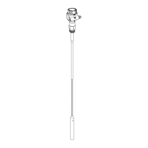
Page 20: Rope Probes Fti56
Length tolerance Up to 1 m: 0 to –10 mm > 1 m to 3 m: 0 to –20 mm > 3 m to 6 m: 0 to –30 mm > 6 m to 20 m: 0 to –40 mm Endress+Hauser... -
Page 21: Installation Instructions
Installation The Solicap M FTI55 (rod probe) can be installed from above and from the side. The Solicap M FTI56 (rope probe) can be installed vertically from above. Note! The probe may not come into contact with the container wall! Do not install probes in the area of the filling curtain! 3.9.2... - Page 22 In this case, the Solicap M FTI55 (rod probe) with inactive length is recommended. In areas where product buildup occurs, the device cannot detect if the silo is "empty". In this case, the FTI56 (rope probe) should be installed from above. Endress+Hauser...
- Page 23 • If you do not know the dielectric constant of the material, contact us for advice. Product properties, relative dielectric constant TI418F12 * Minimum coverage Electrically conductive 25 mm Nonconductive > 10 100 mm r > 5 to 10 200 mm r > 2 to 5 500 mm r Endress+Hauser...
- Page 24 The threaded coupling is too long. This may cause condensation and dust to settle inside which may result in error switching. If too close to the silo wall, the probe may swing slightly against the wall or come in contact with buildup.This can result in error switching. Endress+Hauser...
- Page 25 Heat insulation reduces condensation and therefore buildup on the steel plate. Steel plate; connected to the reinforcing steel Recommended with condensation: Active part Steel plate of probe Heat insulation TI418Fen15 TI418Fen14 Silo with walls that conduct electricity Silo with concrete walls Endress+Hauser...
- Page 26 Ground connection Electrical HF field Weight Surface area e.g. 1 m² Counter electrode e.g. Distance sheet metal plate e.g. 1 m TI418Fen16 In a silo with plastic walls Endress+Hauser...
- Page 27 • Slide the rope back in, as far as the end of the bore, and secure it using the set screws. BA300Fxx018 Endress+Hauser...
- Page 28 Minimum probe length for nonconductive media (<1s/cm) = C / (C * [r - 1]) = Minimum probe length C = 5 pF = Probe capacitance in air (see also ä 81, "Technical data") r = Dielectric constant e.g. dried grain = 3.0 Endress+Hauser...
-
Page 29: Installation
• Do not turn the housing while screwing in the probe, as otherwise the housing fixture can be damaged. BA300Fxx007 3.10.2 Installation tools The following tools are required for installation: • Tool for mounting flanges • or a size 50 Allen key for the threaded connection • and a Phillips-head screwdriver for aligning the cable entry. Endress+Hauser... -
Page 30: With Separate Housing
Rope length L1 max. 19.7 m (the maximum total length of L1 + L4 should not exceed 20 m.) 3.11.1 Extension heights Housing side: wall mounting Housing side: pipe mounting Sensor side ³ ³ TI418F19 Polyester housing F16 Stainless steel housing F15 Aluminum housing F17 Endress+Hauser... -
Page 31: Probe Without Active Buildup Compensation
20. External screening 12. Snap ring (not required) 13. Nut M4 14. Split washer 15. Strand red (RD) with ring terminal insulated with a heatshringking sleeve 16. Blade plug 17. Adapter bushing 18. O - Ring 19. Process connection BA300Fen009 Endress+Hauser... - Page 32 • If the strands are not to be reused, the crimp connections of the new ring terminals attached must be insulated with a heat-shrinking sleeve tube, for example (danger of short circuit). • All soldered joints must be insulated. Use heat-shrinking sleeves to do so. Endress+Hauser...
-
Page 33: Probe With Active Buildup Compensation
12. Snap ring (not required) 13. Nut M4 14. Split washer 15. Strand red (RD) with ring terminal insulated with a heatshringking sleeve 16. Blade plug 17. Guard strand (RD) 18. Adapter bushing 19. O - Ring 20. Process connection BA300Fen009 Endress+Hauser... -
Page 34: Installing Bracket For Wall And Pipe Mounting
• The wall holder unit is part of the scope of supply. • The wall holder unit has to be screwed to the separate housing before you can use it as a drilling template. The distance between the holes is reduced by screwing it to the separate housing. TI418F20 Endress+Hauser... -
Page 35: Post-Installation Check
• Is the process connection tightened with the correct torque? • Are the measuring point number and labeling correct (visual inspection)? • Is the measuring device adequately protected from precipitation and direct sunlight? Endress+Hauser... -
Page 36: Wiring
FEI.. FEI.. max. 2.5 mm² max. 2.5 mm² (max. (max. A A WG 14) WG 14) M20x1.5 M20x1.5 max. 4 mm² max. 4 mm² ø5…9 ø5…9 (max. (max. A A WG 12) WG 12) (ø0.2…0.35 in) (ø0.2…0.35 in) BA300Fxx012 Endress+Hauser... - Page 37 – ground external load / signal L00-FTI5xxxx-04-06-xx-xx-015 4.1.5 Cable entry • Cable gland: M20x1.5 (for EEx d only cable entry M20) Two cable glands included in scope of delivery. • Cable entry: G ½, NPT ½ and NPT ¾ Endress+Hauser...
-
Page 38: Wiring In Housing F16, F15, F17, F13
• All further steps depend on the specific electronic inserts used, which are described on the following pages: ä 41 FEI51 ä 42 FEI52 ä 43 FEI53 ä 44 FEI54 ä 45 FEI55 FEI57S ä 46 ä 47 FEI58 Endress+Hauser... -
Page 39: Wiring In Housing T13
• All further steps depend on the specific electronic inserts used, which are described on the following pages: ä 41 FEI51 ä 42 FEI52 ä 43 FEI53 ä 44 FEI54 ä 45 FEI55 FEI57S ä 46 ä 47 FEI58 Endress+Hauser... -
Page 40: Connecting The Device
Aluminum housing T13 – X*** with gas-tight process seal and separate connection compartment (EEx d) Separate housing – X*** * As per EN60529 ** As per NEMA 250 *** Only with M20 cable entry or G1/2 thread Endress+Hauser... -
Page 41: Connecting The Electronic Insert Fei51 (Ac 2-Wire)
Section 5 "Operation". This will ensure that you do not accidentally trigger any processes by switching on the supply voltage. Switch on the supply voltage. (Masse) U~ max. 253 V AC 50/60 Hz L00-FMI5xxxx-06-05-xx-en-071 Endress+Hauser... -
Page 42: Connecting The Electronic Insert Fei52 (Dc Pnp)
Switch on the supply voltage. L+ L– U – 10…55 V (DC) … * R = External load (I 350 mA, U 55 V DC) max. TI418F42 Endress+Hauser... -
Page 43: Connecting The Electronic Insert Fei53 (3-Wire)
The 3-wire DC connection is used in conjunction with the Nivotester switching device FTC325 3–WIRE from Endress+Hauser; the switching device's communication signal operates at 3 to 12 V. The changeover of failsafe mode (MIN) / (MAX) and the level limit calibration take place on the Nivotester. -
Page 44: Connecting The Electronic Insert Fei54 (Ac/Dc With Relay Output)
Page 49 "Operation". This will ensure that you do not accidentally trigger any processes by switching on the supply voltage. Switch on the supply voltage. * Refer also to Connectable load L– (Ground) U~ 19…253 V (AC) U– 19… 55 V (DC) TI418F47 Endress+Hauser... -
Page 45: Connecting The Electronic Insert Fei55 (8/16 Ma; Sil2/Sil3)
The electronic insert FEI55 meets the requirements of SIL2/SIL3 in accordance with IEC 61508/ IEC 61511-1 and can be used in safety systems with corresponding requirements. An exact description of the requirements in terms of functional safety can be found in document SD278F/00. Endress+Hauser... -
Page 46: Connecting The Electronic Insert Fei57S (Pfm)
0 mA TI418F52 Frequency: 17 to 185 Hz Output signal PFM 17 to 185 Hz (Endress+Hauser) Connectable load • Floating relay contacts in the connected switching unit Nivotester FTC325 PFM, FTC625 PFM (from SW V1.4), FTC470Z, FTC471Z • For the contact load capacity, refer to the technical data of the switching device. -
Page 47: Connecting The Electronic Insert Fei58 (Namur)
Connecting the electronic insert FEI58 (NAMUR) The two-wire connection for a separate switching unit in accordance with NAMUR specifications (IEC 60947-5-6), e.g. FXN421, FXN422, FTL325N, FTL375N from Endress+Hauser. Change in output signal from high to low current in event of limit detection. -
Page 48: Post-Connection Check
• Is the terminal assignment correct? • Is the cable gland tightly sealed? • Is the housing cover screwed on all the way? • If a power supply is present: If the device is operational, the green LED flashes at 5-second intervals. Endress+Hauser... -
Page 49: Operation
LED 2 ( error indicated), yellow LED 3 (✲ switching state) Note! To select a function, press the keys (– and/or +) for at least 2 seconds. Release the keys when the LED signals change. Endress+Hauser... - Page 50 The LED flashes if a calibration has not yet been carried out. *** Only in conjunction with electronic insert FEI55 (SIL). The device is in the SIL mode. To change the current settings, the device must be unlocked ä 64. Endress+Hauser...
-
Page 51: Human Interface And Display Elements For Fei53, Fei57S
Measuring range: The mesasuring range is between 0 to 500 pF. Span: The span is between 5 to 500 pF. 0..500pF 0..500pF Measuring range: The mesasuring range is between 0 to 1600 pF. 0...1600pF 0...1600pF Span: The span is between 5 to 1600 pF. Endress+Hauser... -
Page 52: Human Interface And Display Elements For Fei58
The output switches safety-oriented when the probe is covered (signal on alarm). For use with overfill protection for example Function Display diagnostic code Display calibration situation Perform calibration (during operation) Delete calibration points (during startup) Test key , (disconnects the transmitter from the switching unit) Endress+Hauser... -
Page 53: Commissioning
Carrying out switch point adjustment point adjustment chapter 6.2.7 chapter 6.2.7 Reset calibration, two-point control, build-up mode witching delay, s elf-test, MIN-/MAX failsafe mode, (optional) SIL mode, measuring range p-/download sensor DAT, restore factory setting chapter 6.2.x Operation BA381Fen027 Endress+Hauser... - Page 54 Turn the function switch to position 4. Press the "–" key for at least 2 seconds until the green LED 2 lights up. Release the "–" key when the green LED 2 lights up. Turn the function switch to position 2 to continue the calibration. Endress+Hauser...
- Page 55 Release the "–" key when the green LED 1 starts to flash. The process of saving the empty calibration is finished when the green LED 1 lights up continuously. You can turn the function switch back to position 1 to return to operation. Endress+Hauser...
- Page 56 Release the "+" key when the green LED 5 starts to flash. The process of saving the full calibration is complete when the green LED 5 lights up continuously. You can turn the function switch back to position 1 to return to operation. Endress+Hauser...
- Page 57 Release the "+" key when the green LED 5 starts to flash. The process of saving the full calibration is complete when the green LED 5 lights up continuously. You can turn the function switch back to position 1 to return to operation. Endress+Hauser...
- Page 58 The reset calibration has been carried out and saved. The yellow LED 5 flashes. The device is not operational until you have carried out a new calibration. The switch point adjustment is reset to the factory setting of 2 pF. Endress+Hauser...
- Page 59 "+" or "–" key, the value changes to the next one every two seconds. The active value is indicated by an LED (1 to 5). After you have carried out the switch point adjustment, turn the function switch to position 1 to return to operation. Endress+Hauser...
- Page 60 – Pressing the "+" again for at least two seconds switches off both functions. Green LEDs 4 and 5 are off. After you have configured the desired setting, turn the function switch to position 1 to return to operation. You have now completed the settings for the two-point control and buildup mode. Endress+Hauser...
- Page 61 The possible values are signaled by the LEDs 1 to 4. Set the desired value. You have now set the switching delay and can turn the function switch back to position 1 (operation). Endress+Hauser...
- Page 62 The green operational LED 1 is off. After approx. 20 seconds, the test is completed. This is indicated by the lighting up of the operational LED 1. You have now carried out the self-test and can turn the function switch back to position 1 (operation). Endress+Hauser...
- Page 63 – release the keys when the red LED (fault message) starts to flash. Note! Locking in the "Lock SIL mode" activates the fault message at the current output (I < 3.6 mA). This is signaled by the red LED 3 lighting up. Endress+Hauser...
- Page 64 – Press the "–" and "+" keys simultaneously for approx. 4 seconds and – release the keys when the "MIN-SIL" or "MAX-SIL" LED goes out. • Turn the function switch to position 1 "operation" to operate the device without the SIL mode. Endress+Hauser...
- Page 65 Press the "+" key for at least two seconds to carry out an upload (the data from the sensor DAT (EEPROM) are transferred to the electronic insert). The green LED 5 flashes during upload. You have now transmitted the data and can turn the function switch back to position 1 (operation). Endress+Hauser...
- Page 66 LEDs 1–5 light up consecutively. The factory settings have been successfully restored if the green LED 1 and the yellow LED are flashing. You have now restored the factory settings and can continue with setting the measuring range and the calibration. Endress+Hauser...
- Page 67 < 3,8 mA BA300Fen017 * See ä 78, "Troubleshooting" Output signal FEI52 Safety mode Level Output signal LEDs gn gn rd gn gn ye Maintenance I / I required Instrument failure TI418Fen43 * See ä 78, "Troubleshooting" Endress+Hauser...
- Page 68 Output signal FEI55 Safety mode Level Output signal LEDs gn gn rd gn gn ye ~16 mA ~8 mA ~16 mA ~8 mA Maintenance 8/16 mA required * Instrument failure < 3.6 mA TI418Fen51 * See ä 78, "Troubleshooting" Endress+Hauser...
- Page 69 • With this setting, you can determine the alarm response of the measuring system If the measuring range is exceeded. You can switch the alarm on or off If the measuring range is exceeded. • All other settings with regard to the alarm response have to be configured on the respective Nivotester switching device. Endress+Hauser...
- Page 70 3 at terminal 3 Maintenance Maintenance 3...12 V 3...12 V required * required * at terminal at terminal Instrument Instrument failure failure < 2,7 V < 2,7 V at terminal at terminal TI418Fen46 * See ä 78, "Troubleshooting" Endress+Hauser...
-
Page 71: Commissioning With Electronic Inserts Fei53 Or Fei57S
• The measuring system is not operational until you have carried out a calibration. • Additional functions associated with the switching unit are described in the documentation for the switching unit, e.g. Nivotester FTL325N, FTL375N (for devices from Endress+Hauser). FEI58... - Page 72 Press keys A and B simultaneously for at least 2 s to save the calibration value. The green LED 1 flashes quickly to indicate that the value has been saved correctly. The process of saving the empty calibration value is finished once green LED 1 flashes slowly again. Endress+Hauser...
- Page 73 • A switching delay that is too short may, for example, cause the filling process to be restarted as soon as the medium surface settles. " Caution! If too long of a switching delay is set, this can cause the tank to overflow. DIP switch: E Function Switching delay: 5 s Switching delay: 1 s Endress+Hauser...
- Page 74 This function makes it possible to interpret faults using the three LEDs. If the system detects more than one fault, the fault with the highest priority is shown on the display. Further information is provided in the "Fault diagnostics" section ä 79. Endress+Hauser...
- Page 75 Pressing test key C disconnects the supply voltage. If the power supply is disconnected, a supply unit such as Nivotester FTL325N from Endress+Hauser reacts in such a way that the alarm relay outputs an error and appropriate responses are triggered in any slave devices connected.
-
Page 76: Maintenance
Section 9.2 ( ä 79) you will find a list of all spare parts kits, together with their order numbers, that can be ordered from Endress+Hauser and used to repair the Solicap M. For more information about service and spare parts, contact Endress+Hauser Service. -
Page 77: Accessories
These two versions can be screwed directly into the housing (M20x1.5). • HAW569–A11A (non-hazardous) • HAW569–B11A (hazardous area) Surge arrester for limiting overvoltage in signal lines and components. ÜS-Ableiter/Arrester ENDRESS+HAUSER HAW569 HAW569-A1 Uc 34.8 V In 10 kA IL 500 mA... -
Page 78: Troubleshooting
The DC PNP output is overloaded.* Reduce the connected load. The capacitance change from probe "covered" to Contact Endress+Hauser Service. probe "not covered" is too small. Sensor DAT (EEPROM) data are invalid. Carry out download from the electronic insert. 8 Probe is not detected**. -
Page 79: Spare Parts
Parts number FEI51 71042887 FEI52 71025819 FEI53 71025820 FEI54 71025814 FEI55 71025815 FEI57S 71025816 FEI58 71100895 9.2.2 Housing cover Cover Parts number For aluminum housing F13: gray with sealing ring 52002698 For stainless steel housing F15: with sealing ring 52027000 Endress+Hauser... -
Page 80: Return
V 01.00.XX Original software Contact addresses at Endress+Hauser On the back page of these Operating Instructions, you can find an internet address for Endress+Hauser. The web site provides contact addresses that you can use in case of any questions. Endress+Hauser... -
Page 81: Technical Data
Minimum/maximum quiescent current safety can be switched at the electronic insert (for FEI53 and FEI57S only at Nivotester FTCxxx) MIN = minimum safety: The output switches safety-oriented when the probe is uncovered (signal on alarm). For use for dry running protection and pump protection for example Endress+Hauser... -
Page 82: Performance Characteristics
• A weather protection cover should be used when operating outdoors in strong sunlight. For further information on the weather protection cover, see ä 77. 10.4.2 Storage temperature –50 °C to +85 °C 10.4.3 Climate class DIN EN 60068-2-38/IEC 68-2-38: test Z/AD Endress+Hauser... - Page 83 • Interference emission to EN 61326, Electrical Equipment Class B Interference immunity in accordance with EN 61326, Appendix A (Industrial) and NAMUR Recommendation NE 21 (EMC) • A usual commercial instrument cable can be used. 10.4.8 Shock resistance DIN EN 60068-2-27/IEC 68-2-27: 30g acceleration Endress+Hauser...
-
Page 84: Operating Conditions: Process
–20 –40 –40 –60 –60 TI418F60 Partially insulated (PPS): °C °C °C °C –60 –60 –40 –40 –20 –20 –20 –20 –40 –40 –60 –60 TI418F61 Fully insulated (PE): Note! Restriction to T –40 °C for polyester housing F16. Endress+Hauser... - Page 85 °C °C °C –60 –60 –40 –40 –20 –20 –20 –20 –40 –40 –60 –60 TI418F62 Partially insulated (PTFE): °C °C °C °C –60 –60 –40 –40 –20 –20 –20 –20 –40 –40 –60 –60 TI418F63 Fully insulated (PA): Endress+Hauser...
- Page 86 160 180 180 200 TI418F64 Partially insulated (PPS): °C °C –60 –60 –40 –40 –20 –20 TI418F65 Fully insulated (PE): Rope probe FTI56 °C °C 160 180 180 200 –60 –60 –40 –40 –20 –20 TI418F64 Partially insulated (PTFE): Endress+Hauser...
- Page 87 • ASME B 16.5a- 1998 Tab. 2.3.8 N10276 • JIS B 2220 10.5.3 Temperature-derating separate housing +170 °C +120 +180/ +110 °C –80 –60 –40 –20 –20 –40 –60 BA300Fxx021 : Ambient temperature : Process temperature * temperature at the separate housing 70 °C Endress+Hauser...
-
Page 88: Other Standards And Guidelines
• Solicap M FTI55, FTI56 ATEX II 1 D Ex tD A20 IP65 T 90 °C, ATEX II 1/2 D Ex tD A20/A21 IP65 T 100 °C XA00389F/00/a3 • Solicap M FTI55, FTI56 DIP A21 T , T 100°C IP65 Endress+Hauser... - Page 89 This product is protected by at least one of the patents listed below. Further patents are under development. • DE 103 22 279, WO 2004 102 133, US 2005 003 9528 • DE 203 13 695, WO 2005 025 015 Endress+Hauser...
-
Page 90: Index
Minimum coverage ....... . 23 Upload/download sensor DAT ..... . . 65 Endress+Hauser... - Page 91 Wiring ......... . 36 Endress+Hauser...
- Page 92 71304919 www.addresses.endress.com...