Sign In
Upload
Manuals
Brands
Endress+Hauser Manuals
Measuring Instruments
SpectraSensors J22 TDLAS
Endress+Hauser SpectraSensors J22 TDLAS Manuals
Manuals and User Guides for Endress+Hauser SpectraSensors J22 TDLAS. We have
3
Endress+Hauser SpectraSensors J22 TDLAS manuals available for free PDF download: Operating Instructions Manual, Manual
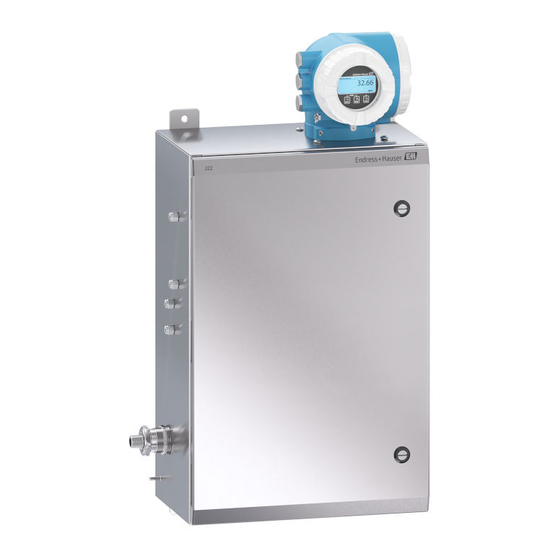
Endress+Hauser SpectraSensors J22 TDLAS Operating Instructions Manual (158 pages)
Gas Analyzer
Brand:
Endress+Hauser
| Category:
Measuring Instruments
| Size: 7.95 MB
Table of Contents
Table of Contents
3
1 Introduction
7
Document Function
7
Symbols Used
7
Safety Symbols
7
Informational Symbols
7
Communication Symbols
7
Tools Symbols
8
Standard Documentation
8
Registered Trademarks
9
Manufacturer Address
9
2 Safety
10
Personnel Qualifications
10
Potential Risks Affecting Personnel
10
Electrocution Hazard
10
Laser Safety
10
Product Safety
11
General
11
IT Security
11
Protecting Access Via Hardware Write Protection
11
Protecting Access Via a Password
12
User-Specific Access Code
12
Access Via Web Server
12
3 Product Description
13
Product Identification
14
Equipment Labels
14
Nameplate
14
Extended Order Code
15
Symbols on the Equipment
15
Electrical Symbols
15
Informational Symbols
15
Warning Symbols
15
4 Installation
17
Tools
17
Required Tools
17
Lifting/Carrying
17
Mounting the Analyzer
17
Turning the Controller Housing
18
Turning the Display Module
19
Cover Locking
19
Protective Chassis and Ground Connections
20
Protective Ground Cable
20
Electrical Connections
21
Connecting the Controller
21
Removing a Cable
23
Connecting Enclosure Heater Power
23
(Optional)
23
Threaded Entries
24
Gas Connections
25
Connecting the Sample Returns
26
Metric Conversion Kit
27
Required Tools
27
Installation
27
Hardware Settings
27
Setting the J22 TDLAS Gas Analyzer Address
28
Hardware Addressing
29
Software Addressing
29
Enabling the Terminating Resistor
29
Ensuring the Degree of Protection
30
5 Operation Options
31
Overview of Operation Options
31
Structure and Function of the Operating Menu
32
Structure of the Operating Menu
32
Operating Philosophy
32
Access to the Operating Menu Via the Local Display
34
Operational Display
34
Status Area
34
Display Area
35
Navigation View
36
Navigation Path
36
Status Area
36
Display Area
37
Editing View
38
Input Mask
38
Operating Elements
40
Opening the Context Menu
41
Calling up and Closing the Context
41
Menu
41
Navigating and Selecting from List
42
Calling up Help Text
43
Changing the Parameters
43
User Roles and Related Access Authorization
45
Access Authorization to Parameters: "Maintenance" User Role
45
Access Authorization to Parameters: "Operator" User Role
45
Disabling Write Protection Via
45
Access Code
45
Enabling and Disabling the Keypad Lock
45
Local Operation with Touch Control
46
Switching off the Keypad Lock
46
Access to the Operating Menu Via the Web Browser
46
Function Range
46
Prerequisites
47
Computer Hardware
47
Computer Settings
47
Computer Software
47
Measuring Device
48
Establishing a Connection
48
Via Service Interface (CDI-RJ45)
48
Starting the Web Browser
49
Logging on
50
User Interface
50
Header
50
Navigation Area
51
Disabling the Web Server
51
Enabling the Web Server
52
Function Scope of the "Web Server Functionality" Parameter
52
Logging out
52
Access to the Operating Menu Via the Operating Tool
52
Connecting the Operating Tool
52
Via Modbus RS485 Protocol
52
Service Interface
53
Via Service Interface (CDI-RJ45)
53
6 System Integration
54
Overview of Device Description Files
54
Modbus RS4852 Information
54
Function Codes
54
Register Information
55
Response Time
55
Modbus Data Map
55
Structure of the Modbus Data Map
56
Scan List Configuration
56
Rs485
56
Reading out Data Via Modbus RS485
56
7 Commissioning
58
Language
58
Configuring the Measuring Device
58
Defining the Tag Name
59
Setting the Analyte Type
60
Selecting the Measurement Calibration
60
Setting the System Units
60
Setting the Dew Point
62
Setting Peak Tracking
63
Configuring the Communication Interface
63
Displaying the I/O Configuration
65
Configuring the Current Output
66
Configuring the Switch Output
68
Configuring the Relay Output
71
Configuring the Local Display
72
Advanced Settings
74
Navigation
75
Stream
75
Carrying out a Sensor Adjustment
76
Setting the Calibration
77
Carrying out the SCC Calibration
78
Carrying out Additional Display Configurations
79
Configuration Management
83
Using Parameters for Device Administration
85
Using the Parameter to Define the Access Code
85
Access Code
86
Device
86
Simulation
86
Protecting Settings from Unauthorized
88
Access
88
Defining the Access Code Via Local Display
88
Write Protection Via Access Code
88
Defining the Access Code Via the Web Browser
89
Parameters that Can Always be Modified Via the Local Display
89
Resetting the Access Code
90
Switch
90
Via Web Browser (Via CDI-RJ45 Service Interface)
90
Write Protection Via Write Protection
90
8 Operation
92
Configuring the Display
92
Reading Measured Values
92
Output Values
92
Output Values of Current Output
92
Output Values for Relay Output
93
Output Values for Switch Output
93
Showing Data Logging
94
Adapting the Measuring Device to the Process Conditions
96
Defining the Tag Name
97
Setting the System Units
97
Configuring the Communication
99
Interface
99
Displaying the I/O Configuration
100
Configuring the Current Output
101
Configuring the Switch Output
103
Configuration Management
106
Using Parameters for Device Administration
108
Using the Parameter to Define the Access Code
109
Using the Parameter to Reset the Access Code
109
Device
110
Simulation
110
Protecting Settings from Unauthorized
112
Access
112
Defining the Access Code Via Local Display
112
Parameters that Can Always be Modified Via the Local Display
112
Write Protection Via Access Code
112
Defining the Access Code Via the Web Browser
113
Resetting the Access Code
113
Switch
113
Via Web Browser (Via CDI-RJ45 Service Interface)
113
Write Protection Via Write Protection
113
9 Diagnostics and Troubleshooting
115
General Troubleshooting
115
For Local Display
115
For Output Signals
116
For Access
116
Emitting Diodes
117
Controller
117
Diagnostic Information on Local Display
118
Diagnostic Message
118
Diagnostic Behavior
119
Diagnostic Information
119
Status Signals
119
Calling up Remedial Measures
120
Operating Elements
120
Diagnostic Information in the Web Browser
121
Diagnostic Options
121
Status Signals
121
Calling up Remedy Information
122
Diagnostic Information Via Communication
122
Interface
122
Configuring Error Response Mode
122
Reading out Diagnostic Information
122
Adapting the Diagnostic Information
123
Adapting the Diagnostic Behavior
123
Overview of Diagnostic Information
123
Pending Diagnostic Events
128
Diagnostic List
129
Event Logbook
130
Event History
130
Filtering the Event Logbook
130
Overview of Information Events
131
Resetting the Measuring Device
132
Function Scope of the "Device Reset" Parameter
132
Device Information
133
Signal Alarms
134
Modbus RS485
134
Current Output 0/4 to 20Ma
134
To 20 Ma
134
Interface/Protocol
135
Light Emitting Diodes (LED)
135
Local Display
135
Relay Output
135
To 20 Ma
135
Web Server
135
Protocol-Specific Data
136
10 Maintenance/Service
137
Cleaning and Decontamination
137
To Keep the Sampling Lines Clean
137
To Clean the J22 TDLAS Gas Analyzer Exterior
137
Spare Parts
137
Troubleshooting/Repairs
137
Replacing the Membrane Separator
137
Filter
137
Replacing the 7 Micron Filter
138
Tools
138
Enclosure Purge (Optional)
139
Sample System Enclosure Purge
140
Optional)
140
Repair Verification
140
Intermittent Operation
140
Packing, Shipping and Storage
141
Preparing the Analyzer for Shipment
141
Or Storage
141
Storage
142
Service Contact
142
Before Contacting Service
142
Factory Return
142
Disclaimers
142
Warranty
142
11 Spare Parts
143
Controller
143
J22 TDLAS Gas Analyzer on Panel
145
12 Technical Data
147
Local Operation
149
Via Display Module
149
Display Elements
149
Operating Elements
149
Supported Operating Tools
150
Web Server
150
Supported Functions
150
Historom Data Management
150
Additional Information on the Data Storage Concept
150
Data Backup
151
Automatic
151
Manual
151
Data Transfer
151
Event List
152
Automatic
152
Data Logging
152
Manual
152
Diagnostics Functions
152
Heartbeat Technology
153
13 System Drawings
154
Advertisement
Endress+Hauser SpectraSensors J22 TDLAS Operating Instructions Manual (150 pages)
TDLAS Gas Analyzer
Brand:
Endress+Hauser
| Category:
Measuring Instruments
| Size: 10.22 MB
Table of Contents
Table of Contents
3
Introduction
5
Document Function
5
Symbols Used
5
Standard Documentation
6
Registered Trademarks
6
Manufacturer Address
6
Safety
7
Personnel Qualifications
7
Potential Risks Affecting Personnel
7
Product Safety
8
Device-Specific IT Security
9
Product Description
11
J22 TDLAS Gas Analyzer Model Types
11
Sample Conditioning System Components
13
Product Identification
13
Equipment Labels
14
Symbols on the Equipment
15
Installation
16
Installing the Heat Trace Boot
16
Lifting/Carrying
16
Mounting the Analyzer
16
Turning the Display Module
21
Protective Chassis and Ground Connections
21
Electrical Connections
22
Gas Connections
31
Metric Conversion Kit
32
Hardware Settings
33
Ensuring IP66 Degree of Protection
37
Operation Options
38
Overview of Operation Options
38
Structure and Function of the Operating Menu
39
Local Operation
41
Accessing the Operating Menu through the Local Display
41
Operating Elements
46
Access to the Operating Menu from the Web Browser
51
Remote Operation Using Modbus
56
Modbus Communication
57
Overview of Device Description Files
57
Modbus RS485 or Modbus TCP Function Codes
57
Response Time
57
Modbus Data Map
58
Modbus Registers
59
Commissioning
60
Language
60
Configuring the Measuring Device
60
Defining the Tag Name
61
Setting the Analyte Type
61
Selecting the Measurement Calibration
61
Setting System Units
62
Setting the Dew Point
62
Setting Peak Tracking
63
Configuring the Communication Interface
64
Configuring the Current Input
65
Configuring the Current Output
66
Configuring the Switch Output
68
Configuring the Relay Output
69
Configuring the Local Display
70
Advanced Settings
72
Operation
79
Reading Measured Values
79
Showing Data Logging
81
Adapting the Measuring Device to the Process Conditions
83
Simulation
85
Protecting Settings from Unauthorized Access
86
Verification, Diagnostics and Troubleshooting
89
Diagnostic Information from Light Emitting Diodes
89
Diagnostic Information on Local Display
90
Diagnostic Information in the Web Browser
92
Diagnostic Information through the Communication Interface
93
Adapting the Diagnostic Behavior
93
Overview of Diagnostic Information
94
Pending Diagnostic Events
97
Event Logbook
98
Resetting the Measuring Device
99
Device Information
100
Signal Alarms
100
Protocol-Specific Data
102
General Troubleshooting
103
Maintenance/Service
106
Cleaning and Decontamination
106
Spare Parts
106
Troubleshooting/Repairs
106
Intermittent Operation
110
Packing, Shipping, and Storage
111
Service Contact
111
Disclaimers
112
Warranty
112
Spare Parts
113
Controller
113
J22 TDLAS Gas Analyzer
114
J22 TDLAS Gas Analyzer on Panel
115
J22 TDLAS Gas Analyzer with Enclosure
116
Controller Spare Parts Details
117
Sample Conditioning System Spare Parts Details
125
Technical Data
138
Electrical and Communications
138
Application Data
138
Physical Specificiations
139
Area Classification
139
Supported Operating Tools
140
Web Server
140
Historom Data Management
141
Data Backup
141
Manual Data Transfer
142
12.10 Automatic Event List
142
12.11 Manual Data Logging
142
12.12 Diagnostics Functions
142
12.13 Heartbeat Technology
142
Drawings
144
Dew Point Conversion
148
Introduction
148
MDP Calculation
149
Endress+Hauser SpectraSensors J22 TDLAS Manual (32 pages)
Brand:
Endress+Hauser
| Category:
Measuring Instruments
| Size: 1.46 MB
Table of Contents
Table of Contents
3
Introduction
5
Intended Equipment Use
5
Associated Documentation
5
Manufacturer's Certificates
5
Manufacturer Address
6
General
7
Symbols Used
7
Safety Symbols
7
Informational Symbols
7
Electrical Symbols
7
Labels
8
Nameplate
8
Controller
8
Personnel Qualifications
8
General
9
Equipment Training
9
Potential Risks Affecting Personnel
9
Electrocution Hazard
10
Laser Safety
10
Analyzer Technical Specifications
10
Electrostatic Discharge
13
Chemical Compatibility
13
Equipment Installation
14
Required Hardware/Tools
14
Tools Symbols
14
Lifting/Carrying the Analyzer
14
Mounting the Analyzer
15
Opening/Closing the Analyzer Enclosure
16
Protective Chassis and Ground Connections
16
Protective Ground Cable
16
Ground Connections
17
Electrical Wiring Requirements
18
Wire Temperature Rating and Torque
18
Cable Entries
19
Threaded Entries
19
Cables Type
20
Flow Switch Connection Requirements
20
Connection Values: Signal Circuits
20
Terminal Assignment
20
Safety-Related Values
21
Modbus Interface Cable Specification
21
Electrical Circuit Breakers
21
Connecting the Gas Supply
22
Sample System Heater
22
Equipment Operation
23
Operating Controls
23
Commissioning
23
Decommissioning
23
Intermittent Operation
23
Maintenance and Service
25
Cleaning and Decontamination
25
To Clean the J22 Exterior
25
Troubleshooting and Repairs
25
Cleaning the Cell Mirror
25
Replacing the Membrane Separator Filter
27
Enclosure Purge (Optional)
28
Sample System Purge (Optional)
29
Repair Verification
29
Power Termination Covers
29
Spare Parts
29
Service Contact
29
Advertisement
Advertisement
Related Products
Endress+Hauser 11362Z
Endress+Hauser 11363Z
Endress+Hauser 11375Z
Endress+Hauser 11961Z
Endress+Hauser 2-Pack TDLAS
Endress+Hauser 3-Pack TDLAS
Endress+Hauser 3Deltapilot M FMB52
Endress+Hauser 507000 3W
Endress+Hauser 9P5B
Endress+Hauser Categories
Measuring Instruments
Transmitter
Radar
Switch
Accessories
More Endress+Hauser Manuals
Login
Sign In
OR
Sign in with Facebook
Sign in with Google
Upload manual
Upload from disk
Upload from URL