AVE VSI-Pro Max Operation Manual
Pos / cash register interface
Hide thumbs
Also See for VSI-Pro Max:
- Operation manual (76 pages) ,
- Operation manual (84 pages) ,
- Instruction manual (1 page)

Related Manuals for AVE VSI-Pro Max


Summary of Contents for AVE VSI-Pro Max
- Page 1 VSI-PR VSI-PR O O O O O VSI-PR VSI-PR VSI-PR POS / CASH REGISTER INTERFACE Operation Manual January 2013...
- Page 2 Email: ave-uk@multiview.net www.americanvideoequipment.com www.ave.co.th (Thai) www.multiview.net www.avethailand.com (English) AVE Europe LTD 123 Millennium Business Park Ballycoolin, Dublin 15, Ireland Tel:353 1 684 7450 Fax: 353 1 684 7451 Email; sales@ave-europe.eu Website: www.ave-europe.eu www.ave-global.com Copyright C AVE Thailand Co., Ltd. 2013...
-
Page 3: Table Of Contents
CONTENTS 1. Introduction ........................................8 1.1 VSI / VSI+ / VSI-Pro / VSI-Pro Max Backward Compatibility .....................8 2. Features & Specifications ..................................9 2.1 Features .......................................9 2.2 Specifications ..................................10 3. Connections ........................................11 3.1 LED Indicators ..................................11 3.2 RS-232/RS-485/RS-422 Serial Connections ......................12 - 13 4. - Page 4 Capture Port 1, 2 to Memory ........................64 Dump Memory ..............................65 Register Demo .................................65 Version ID ..................................65 5.10 Download/Upload Setup ..............................66 Download/Upload Setup Using VSI-Pro Max to VSI-Pro Max ................66 Download/Upload Setup Using a PC ...........................68 PC Programming Software ..........................68 Update Firmware ................................71 5.11 Help ......................................74 Problem Solving Guide ................................74...
- Page 5 Figure 5 : VSI-Pro Max Earth Grounding Connection ....14 Figure 36 : Dresser Wayne Sub-Menu ........22 Figure 6 : Four Front Panel Push Button of VSI-Pro Max ..15 Figure 37 : POS/CDU Sub-Menu ..........22 Figure 7 : Front Panel Push Button of VSI-Pro Max (Down) 15 Figure 38 : Nucleus Sub-Menu ..........22...
- Page 6 Figure 183 : Upload Setup Sub-Menu & Display ...68 Figure 121 : Team POS 3000 Sub-Menu ......33 Figure 183A : Four Front Panel Push Buttons of VSI-Pro Max Figure 122 : TEC Sub-Menu Page 1 ........33 for PC Programming Temporary Access ...69 Figure 123 : TEC Sub-Menu Page 2 ........33...
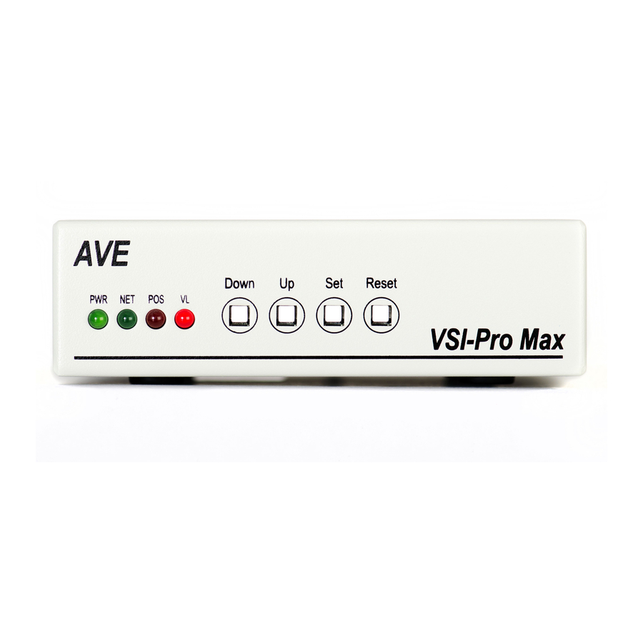
- Page 7 Figure 227 : TCPIP232 Client/Serverwith AVE Networking 92 Figure 228 : TCPIP232 Client/Server Direct IP ....92 Figure 229 : DS-20-OF Rack of 16 VSI-Pro Max ..94 Figure 230 : RJ45 Network Connector ......94 Figure 231 : AVE RS-485 Networking ......95 Figure 232 : VSI-Pro Max Front Panel ......96...
-
Page 8: Introduction
This utilizes a direct connection via RS-232 from a laptop to the VSI-Pro Max. Complete VSI-Pro Max settings can be saved on the laptop and uploaded to the VSI-Pro Max at will. Up to 16 VSI-Pro Max can be programmed from one RS- 232 connection on the Master unit over the AVE Network. -
Page 9: Features & Specifications
....Local Firmware Downloadable ....Local / Remote Programming via PC Software or Compatible DVR ....Full Programming and Firmware update over the AVE Network for up to 16 VSI-Pro Max ....Compatible with AVE AL-16 External Relay Interface adapter for additional Hard Alarm Outputs ....Supports AVE UART daughter board for full compatibility with standard 16550 UART and gives full emulation... -
Page 10: 2.2 Specifications
145L x 127W x 43H (mm) or 5.7L x 5W x 1.7H (in) Packed in White Box with Manual 1.02 Kg or 2.26 lbs; 340L x 190W x 85H(mm) or 13.4L x 86.2W x 3.35H(in) VSI-Pro Max POS / Cash Register Interface... -
Page 11: Connections
Pro Max. The BNC video output goes out to the video system (VCR, DVR, quad, switcher, multiplexer, or monitor). This connection is shown in Figure 4. The video output from the VSI-Pro Max is 1[V] Peak to Peak into a 75 [ohm] load. Most monitors or televisions with direct video inputs are terminated with a 75 ohm load. -
Page 12: Table 1: Pin-Out Of The Db-9 Female Connector On The Vsi-Pro Max
3.2 RS-232 SERIAL INPUT The VSI-Pro Max accepts serial data via the DB-9 Female connector located on the rear of VSI-Pro Max. This connector is similar to “AT” type computer RS-232 serial ports and the pin out is identical. Table 1 shows the standard pin out for VSI-Pro Max RS-232 female connector. -
Page 13: Figure 4: Vsi-Pro Max Connections
PC Software Application WALL TRANSFORMER 9-12VDC 300mA RS-232 or RS-485 Direct or Interface VSI-Pro Max CASH REGISTER RG-59U MONITOR To Earth Ground for Lightning and Surge Suppression RG-59U CAMERA Figure 4: VSI-Pro Max Connections VSI-Pro Max POS / Cash Register Interface... -
Page 14: Figure 5 : Vsi-Pro Max Earth Grounding Connection
Power Surge / Lightning Suppression The VSI-Pro Max has MOV (Metal Oxide Varistors) across the power input to signal ground and from both of these signal to chassis ground clamping at 18VDC. For this suppression to be fully effective the “Earth” grounding lug between the two BNC connectors must be connected to a solid and true earth ground. -
Page 15: User Front Panel Controls
4. USER FRONT PANEL CONTROLS The VSI-Pro Max is programmed by pressing and releasing specific combinations of the four front panel push buttons. Via these four simple buttons, all of the powerful programming features of the Text Inserter are available. A video source and a monitor must be connected in order to see the programming menus. - Page 16 Figure 9A: Four Front Panel Push Buttons of VSI-Pro Max for PC Programming Temporary Access Hold in the “Up” and “Set” buttons for longer than 3 seconds and the VSI-Pro Max will temporarily be configured for RS- 232 Register Input at 9600 baud. If you have video connected you will see this message on-screen as well. This mode is also signified by the REGISTER LED and NETWORK LED flashing.
-
Page 17: 5.1 Getting Started
If a sub-menu has an “EXIT” selection, always go there and press "Set". Pressing "Reset" at the main-menu exits you from the programming mode and may not save your selections. 5.2 MAIN PROGRAMMING MENU Following is a detailed description of the menu selections and the programming capabilities of the VSI-Pro Max. REGISTER SELECT SCREEN SETUP... -
Page 18: Generic
Make sure a TCPIP232 Adapter is connected character in the video. If you are not sure of what you are and the VSI-Pro Max will download the IP settings to connecting to this is the first selection so you will see this device. -
Page 19: Addressable Vsi (Vsi-Add)
“ANSI” and press “ Set ”. throughput of the adpater is limited to 5MB/s. This is more This selects an ANSI driver for the VSI-Pro Max. In this than enough for network printers for cash receipts, bar mode standard ANSI terminal commands sent to the VSI- code scanners or single cash registers that operate in a Pro Max will control the display of the data on the screen. -
Page 20: Figure 21 : Casiosub-Menu
“CASIO TE-4000” and press “Set”. The CASIO TE-4000 - - - - NEXT PAGE menu will appear: EXIT MODE: TAPPING Figure 23: Casio Sub-Menu Page 3 EXIT Figure 27: Casio TE-4000 Sub-Menu MODE Choices: TAPPING, EMULATING VSI-Pro Max POS / Cash Register Interface... -
Page 21: Figure 29: Casio Sub-Menu
Press the “Up” or “Down” button to move the cursor to “DIGIPOS” and press “ Set ”. The DIGIPOS menu will ap- Figure 31: Casio TK-T500 Sub-Menu pear: MODE PRINTER/CUSTOMER DISPLAY Choices: TAPPING, EMULATING 2000 MILLENIUM SNA SOFTWARE EXIT Figure 35: DIGIPOS Sub-Menu VSI-Pro Max POS / Cash Register Interface... -
Page 22: Figure 36: Dresser Wayne Sub-Menu
STANDARD [Both] POLE VIA PRINTER PRINTER WITH POLE RECEIPT PRINTER ONLY POLE VIA PRINTER - - - - NEXT PAGE EXIT EXIT Figure 40: NUCLEUS PRINTER Sub-Menu Figure 44: Epson Generic Menu Page 1 VSI-Pro Max POS / Cash Register Interface... -
Page 23: Figure 44 : Epson Generic Sub-Menu
Press the “Up” or “Down” button to move the cursor to SX680 “9920” and press “ Set ”. The FUJIZU 9920 menu will ap- EXIT pear: DISPLAY RECEIPT Figure 52: GELLER Sub-Menu Page 2 EXIT Figure 49: FUJITZU 9920 Sub-Menu Choices: Journal, Receipt VSI-Pro Max POS / Cash Register Interface... -
Page 24: Figure 54: Gilbarco Sub-Menu
16550 UART for 7 bit communication. However the pear: Gilbarco Passport can be set for any baud rate, bits and parity which will work directly with the VSI-Pro Max but the Gilbarco dealers normally only set for 7 bit , no parity EMULATE so requires the AVE UART daughter board. -
Page 25: Figure 59: Icl Sub-Menu
Gold G-381 two lines at any given time. If you select Scroll then the Gold-556 display will scroll continuously like a normal receipt EXIT printer. Figure 66: JCM Sub-Menu VSI-Pro Max POS / Cash Register Interface... - Page 26 Figure 68: MICRELEC Sub-Menu This is selected when connecting to the PC Based Mi- cros VSS software server from AVE Address 15. Press the “Up” or “Down” button to move the cursor to “MICRELEC MS SERIES” and press “Set”. The...
- Page 27 HANDSHAKING for more information on VSI-Pro Max jumper settings. EXIT You will also need to configure the AVE RS-232 to RS- 422/RS-485 converter to be RS-232 to RS-422. See Ap- Figure 75: MICROS 3700 V4.X Sub-Menu pendix J, Page 84 for more information.
- Page 28 Figure 86: PANASONIC Sub-Menu CONSOLE ID : MODEL Choices: ANY, 1, 2, 3, 4, 5, 6, 7, 8 Choices : 6000, 7000, 8000 WORKING MODE WOKING MODE Choices: ACK , TAP Choices : ACK , TAP VSI-Pro Max POS / Cash Register Interface...
- Page 29 Press the “Up” or “Down” button to move the cursor to “PC COM 1,2,3,4” and press “ Set ”. No menu will apprear - - - - PREVIOUS PAGE and merely sets the VSI-Pro Max to “Generic” mode. POS LIGNE POSIFLEX...
- Page 30 Press the “Up” or “Down” button to move the cursor to EXIT “ER-1880” and press “Set”. The sub menu will appear: Figure 97: RIVA Sub-Menu MODE: EMULATING EXIT Figure 100: ER-1880 Sub-Menu MODE Choices: Tapping or Emulating VSI-Pro Max POS / Cash Register Interface...
- Page 31 A-750/AA-770 / ER-01PU A-770 UP600 / 700 SET ADDRESS 0-99 UP3000 / 3300 EXIT - - - - NEXT PAGE EXIT Figure 104: NE134 COUNTER Sub-Menu Figure 108: Sharp Sub-Menu Page 3 VSI-Pro Max POS / Cash Register Interface...
- Page 32 STAR EPOS STATION MASTER SMART POS EMULATE SUNTRONIC SWEDA 54XX Figure 112: SHARP UP600/700 Sub-Menu SWINTEC 2250 TEAM POS - - - - NEXT PAGE EXIT Figure 116: Register Selection Menu Page 12 VSI-Pro Max POS / Cash Register Interface...
- Page 33 SCROLL given time. If you select Scroll then the display will scroll continu- EXIT ously like a normal receipt printer. Figure 121: TEAM POS 3000 Sub-Menu VSI-Pro Max POS / Cash Register Interface...
- Page 34 ANY ADDRESS Choices: ON, OFF NOTE: Device Address 1-999, press set to increment to the digits and press UP and Down simultaneously to save the ad- dress. Select “Any Address” On or Off. VSI-Pro Max POS / Cash Register Interface...
- Page 35 UP and Down simultaneously to save the ad- dress. Select “Any Address” On or Off. - - - - PREVIOUS PAGE VECTRON VERIFONE WEIGH SCALE WINCOR EXIT Figure 135: Register Selection Menu Page 14 VSI-Pro Max POS / Cash Register Interface...
- Page 36 - - - - PREVIOUS PAGE TOLEDO 8142 DIRECT OUTPUT NOTE VISHAY WEIGHBRIDGE EXIT As we continually add new registers, these menus are subject to change. Figure 139: WEIGH SCALE Sub-Menu Page 2 VSI-Pro Max POS / Cash Register Interface...
-
Page 37: 5.4 Screen Setup
To program the clock's functions, press the “Up” or “Down” button to move the cursor to “CLOCK” and press “Set”. The following menu will appear: T/D DISPLAY TIME FORMAT 12 HOUR DATE FORMAT MM/DD/YY DAYLIGHT SAVING DISABLED Figure 144: CLOCK Sub-Menu SET TIME / DATE RESET TIME / DATE T/D LOCKING EXIT VSI-Pro Max POS / Cash Register Interface... - Page 38 DISPLAY turns the T/D locking feature on or off. If ON then will lock the T/D of the VSI- Pro Max to the incoming POS data. If turned off then will not lock and use the free running clock of the VSI-Pro Max. Press the “Up” or “Down” button to move the cursor to “DISPLAY”...
- Page 39 Then if Time Sync is ON will transmit this time/date to the DVR to lock the DVR to the VSI-Pro Max which is locked to the cash register. Refer to Appendix R Page 96-97.
-
Page 40: 5.5 Text Display
Choices: NONE, RTS, 1, 3, 5, 10, 15, 20, 30, 60, 120, 180, 240 seconds This is the amount of time that the VSI-Pro Max text display will remain on-screen after a transaction before erasing or blanking itself off (not the video picture, just the register transaction data) until the next transaction. If set for RTS, this means when RTS input Pin 7 is connected to ground or low then the screen will display normally. -
Page 41: Display Format
Space Compress allows you select the number of maximum spaces next to each other in a line. The selections are 1,2,3,4,5 and OFF. If you select “1” then if three spaces are shown on the receipt the VSI-Pro Max will delete 2 and only show 1 space between characters on the video and on the output data to the DVR. -
Page 42: Communication
POS or Cash Register using the DB9 connector. The “Network Settings” selects and allows you to program the communication and protocol parameters used to network the VSI-Pro Max to other units using the AVE RS- 485 Network via the RJ45 connectors. -
Page 43: Parity
VSI-Pro Max does not require handshaking. The VSI-Pro Max handshaking signal is true or high, signally the cash register or computer to send data until it goes false or low which means the VSI-Pro Max buffer is full and not to send additonal data. -
Page 44: Software Handshaking
When Interface Type is set for RS-232, the “OUTPUT” RS-232 data with the selected format in the Register Select/TX Protocol is sent out the DB9 TXD Pin 3. In the RS-232 mode you can still use the VSI-Pro Max to interface to a POS or Cash Register but only in the tap mode using the DB9 RXD Pin 2 only to recieve the data. - Page 45 RegCom device can be set for either 9600 or 57600 baud rate to match the installed device settings. However when not using the RegCom device and using only VSI-Pro Max then any baud rate can be set. The RegCom Protocol only has the ability to receive register data only to be backward compatible with RegCom device connected with a VSI-Pro.
-
Page 46: Network Program
You will be able to change the Network Protocol and address of the VSI-Pro Max Master so if you do and it is not the same as all the slaves then will not be able to communicate to any slaves. If you add any additional device of an AVE product via the RS-485 network they also must be the same protocol and address unique. -
Page 47: Network Master Reset
TYPE, ADDRESS ID and RS-485 network protocol of a slave device, you must use the OSD buttons of the VSI-Pro Max or the PC Programming Software by connecting to the RS-232 Register port of each slave device independently. -
Page 48: Exception Report
DVR on any questionable transaction that you have preprogrammed into the VSI-Pro Max. The VSI-Pro Max will allow programming of up to 24 separate exceptions. These exceptions can be VOIDS, REFUNDS, COUPONS, PAID OUT, RETURNS, individual departments, specific items, or any transaction that you determine (by programming) to be “exceptional”... -
Page 49: Exception History
DVR or serial printer. If you turn the on-screen display off and the output on and you have a remote serial printer hooked up to the VSI-Pro Max, then, whenever an exception is reported, it is sent out to the serial printer only. - Page 50 Then press “Set” and the DVR will be commanded by the VSI-Pro Max to go to the selected transaction via its Time/Date Search function. Therefore you must make sure the T/D of the DVR is very close to the setting of the VSI-Pro Max or their will be an effor in the actual search time.
- Page 51 DVR control signals. Therefore in this mode you can operate the VSI-Pro Max in the “Slave Mode” and connect to control the DVR via Pin 3. You can not use the VSI-Pro Max in the “Master Mode”. If you select “Master Mode” this will have priority and when you select DVR Time/Data Search you will generate an error message.
-
Page 52: Display
Choices: ON, OFF The OUTPUT controls the RS-232 data from the VSI-Pro Max to the external device like DVR. Typically this is sent to a remote Serial Printer to provide a hard copy of Exceptions with time and date on it or a DVR for database logging. This data can also be sent out to a computer with appropriate software and give you the ability to analyze data. - Page 53 VSI-Pro Max. This can be used to automatically search a compatible DVR, upload to a PC to save or print out and view on screen on the VSI-Pro Max. This setting allows the user to enable or disable this feature as to conserve memory allocation for other features.
-
Page 54: Range
NEGATIVE EXCEPTION You can remove unwanted text from the screen using the VSI-Pro Max. The VSI-Pro Max displays data in the text block 11 lines by 40 characters wide for total of 440 characters. To remove unwanted messages from the register data you first determine how the unwanted messages prints to the video. - Page 55 Suppose Exception # 5 would flag all transactions between $50.00 & $100.00 on Department 3: Exception No. Display Output ON or OFF (Depending on presence of serial printer). Exception String3 ... Range 0049.99-0099.99 Operator With this exception all sales between $50 and $100 dollars will be flagged. VSI-Pro Max POS / Cash Register Interface...
-
Page 56: Output
This function is useful when used with Customer Displays that continuously refresh the display with identical data and not related to new transactions and causes unecessary data to be sent to the interface. VSI-Pro Max POS / Cash Register Interface... -
Page 57: Scroll Matching
EXIT Figure 164: ALARM OUTPUTS Sub-Menu NOTE: The ALARM OUTPUTS menu controls not only the formatting of the external alarms but also the format- ting of the on-screen flags assigned to individual exceptions. VSI-Pro Max POS / Cash Register Interface... - Page 58 Choices: 1, 2, 3, 4, 5, 6, 7, 8, 9, 10, 11, 12, 13, 14, 15, 16 The VSI-Pro Max allows up to 16 alarms that may be used with any of the user programmed exceptions. However there are only 2 hardwired alarm outputs and these correspond to Alarm 1 & 2 only. The other 14 alarms can be used to send trigger text, serial data out or flash the screen.
-
Page 59: Alarm Duration
Triggered Text. To program the TRIGGERED TEXT, go to the ALARM OUTPUTS sub-menu. Select desired ALARM NO or RTS for external alarm. Then go to the TRIGGERED TEXT sub-menu. DISPLAY TEXT OUTPUT TEXT RTS TRIGGERED DELAY CLEAR SCREEN SET TRIGGERED TEXT EXIT Figure 165: TRIGGERED TEXT Sub-Menu VSI-Pro Max POS / Cash Register Interface... -
Page 60: Clear Screen
(linefeed) at the beginning of the Trigger Text string so you move to the next line to display the Trigger Text. EXIT Press the “Up” or “Down” button to move the cursor to “EXIT” and press “Set” to return to the previous menu. VSI-Pro Max POS / Cash Register Interface... -
Page 61: Video Loss
RECEIVE [ RX ] TEST The purpose of this test is to determine that if VSI-Pro Max is receiving the data or not. Press the “Up” or “Down” button to move the cursor to “RECEIVE [ RX ] TEST”. The following display will appear (example only):... - Page 62 TRANSMIT [ TX ] TEST The purpose of this test is to determine that if the VSI-Pro Max is able to transmit data or not. Press the “Up” or “Down” button to move the cursor to “TRANSMIT [ TX ] TEST” and press “Set”. The following display will appear (example only):...
-
Page 63: Capture Port 1 To Port 1
POS terminal to “Tap” the data and be read by both the VSI-Pro Max and the printer. Therefore whatever is sent to the printer will be sent to the VSI- Pro Max. - Page 64 CAPTURE PORT 1 TO PORT 1 This feature redirects the incoming data of the VSI-Pro Max Register Port or Port 1 to its output ( Pin 3 of AT type RS-232 female connector ) where that data can be stored to a data storing device (e.g. PC). This feature is useful to store non- RS 232 format data.
- Page 65 CAPTURE PORT 1 TO MEMORY This feature allows you to store the data in the internal memory of VSI-Pro Max from the Register Port 1. You can store up to 120 kilobytes of data in the internal memory of VSI-Pro Max. Power up the VSI-Pro Max for 24 hours prior to download of data.
-
Page 66: Dump Memory
If you connect the VSI-Pro Max to a cash register and it sends data to the VSI-Pro Max during this demo mode then the demo mode will also be disabled until you press “Reset”... -
Page 67: 5.10 Download/Upload Setup
The PROGRAMMED VSI-Pro Max will upload data to the UNPROGRAMMED VSI-Pro Max. In the configuration in the Figure 180, you can get the programming menus for both VSI-Pro Max on the screen at the same time. Use the front panel shortcut to position the text block from the PROGRAMMED VSI-Pro Max on the left side of the screen. To do this, press and hold down “Up”, then press and release “Reset”... -
Page 68: Download/Upload Setup Using A Pc
You can use a Laptop PC and AVE’s IC, HyperTerminal or equivalent communications program to store data from a VSI-Pro Max to a file. This file can then be uploaded to other VSI-Pro Max units with the same software revision level. - Page 69 Figure 183A: Four Front Panel Push Buttons of VSI-Pro Max for PC Programming Temporary Access Hold in the “Up” and “Set” buttons for longer than 3 seconds and the VSI-Pro Max will temporarily be configured for RS- 232 Register Input at 9600 baud. If you have video connected you will see this message on-screen as well. This mode is also signified by the POS and NETWORK LEDS flashing.
- Page 70 Figure 185: Remote Menu Click on “Set Comport”. If the VSI-Pro Max is in the “Baudrate Detection” Mode then you can set any baud rate and the VSI-Pro Max will self configure. However if the VSI-Pro Max is already set to a baud rate you must select the exact baud rate and communication configuration in the VSI-Pro Max for connection to occur.
- Page 71 Communication Cable Pin Out The Com cable is RS-232 from the PC or laptop to the VSI-Pro Max as follows. This cable can be no more than 100’ but if additional length is required you will need a set of the AVE RS-232 to RS-422 adapter which will extend the range to 3000’.
- Page 72 Proceeding past this point will permanently erase the firmware in the VSI-Pro Max and connect with the firmware update utility in the VSI-Pro Max and update the firmware. You will see the following progress boxes for connecting and updating below.
- Page 73 Confirm the firmware path and Communication parameters and when verified continue by following the instructions in the dialog boxes below. You must power down the VSI-Pro Max and then power back up and press Reset before starting the update utility again.
-
Page 74: Update Firmware
Update Firmware of VSI-Pro Max You have to connect the VSI-Pro Max with a Serial Program Terminal such as HyperTerminal, IC etc. But advise to use HyperTerminal.First, you have to set the baud rate HyperTerminal to 115,200. Note: Make sure you do not have the “Scroll Lock”... - Page 75 Set Flow Control Handshaking to “NONE” Figure 191A: Communications Settings Menu Choose Bits per second to 115200 and press OK and then Connect and verify the telephone icon handset is up. Figure 192: Baud Rate Settings Menu VSI-Pro Max POS / Cash Register Interface...
- Page 76 To do this just power up the VSI-Pro Max or press reset while the terminal program is connected and you will see the prompt messages as above window.
-
Page 77: 5.11 Help
1. Check the cable to the register. 2. If VSI-Pro Max was working and stopped, power cycle the system. Turn off the register, unplug the power to the N2RS, and unplug the power to the VSI-Pro. Now power up the system, plug in the VSI-Pro and the N2RS. Turn on the register and do a transaction. -
Page 78: Appendix A : Problem Solving Guide
1. Darken the gray scale of the characters. 2. The VSI-Pro Max requires the input video signal to be 0.5VP-P to 2V P-P. If the voltage is too high or low, then the VSI has trouble syncing the text to the video. Use an amplifier such as AVE’s VDA-401 or VECA to get the proper level. - Page 79 DVR to lock to and show a good image. If the inserted text from the VSI-Pro Max is stable then the VSI-Pro Max is able to lock to this low signal. If the text jitters or is skewed then a video amplifier must be placed in line with the VSI-Pro Max to bring the signal up to at least .5V P-P so the AGC circuitry can adjust to the...
-
Page 80: Appendix B : Hard Alarm Output
The VSI-Pro Max provides two open collector transistor alarm outputs to trigger alarming devices. These are Alarm 1 & 2 in the Alarm menu. Upon an Exception, a VSI-Pro Max can be programmed to trigger a DVR or VCR to go to its fastest record time, have a Quad go full screen, home a switcher, trigger a preprogrammed PTZ, or provide visual or audible alarms. -
Page 81: Appendix C : Dvr Text Input Connections
DVR. If you are using the VSI-Pro Max for “Slave Mode” networking then you can not use the RJ45 RS-485 or RS-232 Pin 8 as an output to the DVR and only RS-232 is available from Pin 3. If you are not using the VSI-Pro Max in the “Slave Mode”... -
Page 82: Appendix D : Utp Connections
The VSI-Pro Max has an AGC (Automatic Gain Control) circuit on the video input. This means that even if the video signal is as low as 0.5 V P-P the VSI-Pro Max will automatically amplify to the proper level of 1 V P-P and insert the cash register data into the video flawlessly. -
Page 83: Appendix E : P2Rs/P2Rs-Pro Parallel To Serial Converter
Centronics Parallel printer data from a normal or enhanced LPT port of any POS or PC. This data also is exported via the Data RS-232 port in ASCII format to the VSI-Pro or VSI-Pro Max line of text inserters or directly to a DVR for display or database storage. - Page 84 USB Ports are also commonly connected to printers. The AVE USB232 adapter will emulate a printer and output RS- 232 data to the VSI-Pro Max. A software driver is supplied with the unit which needs to be installed on the PC based POS prior to running the POS Software.
-
Page 85: Appendix G : Vsib Installation
8 CTS GND 5 5 GND Figure 213: Pin-Out for VSIB to VSI-Pro Use the BNC con- nectors of the VSIB for your Video Input & Output Figure 212: Cable Connection to VSIB VSI-Pro Max POS / Cash Register Interface... -
Page 86: Table 5: Ansi Driver Commands
RS-232 cable fitted through the rear of the till. These interfaces output direct converted and formatted RS-232 of the printer. This data can be connected directly to the AVE line of DVRs without additional conversion up to 100’. If additional lengths are needed then the AVE RS-232 to RS-422/485 converter can be used to extend this range to 3000’. - Page 87 3000 ft. Then on the other end another converter would convert back to RS-232. When using the VSI-Pro Max this additional converter is not required for already has built in RS-485 compatibility. However termination for the POS / Cash Register port is via JP2 internally to the VSI-Pro Max is required.
-
Page 88: Appendix K : Uart Module
“REGISTER SELECT” menu then exit to the Main Menu. Press the “Up” or “Down” buttons to move the cursor to “Communication” menu then set a PARITY sub menu is NONE and set DATA BITS sub menu is 7. If VSI-Pro Max cannot communicate with the daughter board, This message will appear on the screen."... -
Page 89: Appendix Lregcom Ibm
IBM High Speed RS-485 network to ASCII RS-232 for connection directly to a VSI-Pro Max or DVR. AVE offers a full line of cables that use the IBM SDL connectors to plug directly to the IBM POS either 4 Pin Display ports or the 16 Pin Printer port. - Page 90 TCPIP 232 ADAPTER Interfacing the VSI-Pro Max to the POS / Cash Register TCP/IP network requires the TCPIP 232 Adapter along with the VSI-Pro Max. The IP address of the cash register is programmed into the TCPIP 232 Adapter via on-screen programming.
- Page 91 A special version of the TCPIP232 Adapter is called the POS Client Server. The POS Client version can read RS-232/ RS485 data from a POS or VSI-Pro Max and send this data over the LAN network directly to compatible DVRs or to the POS Server.
- Page 92 APPENDIX M This diagram shows how you can use AVE RS-485 Network for up to 16 POS and use the TCPIP232 Client as a Master of the AVE RS-485 Network and read data from up to 16 VSI-Pro Max configured as Slaves. The TCPIP232 Client will then send all the POS data on the LAN network and be decoded by the TCPIP232 Server which then outputs all the POS data in the AVE VSI-ADD protocol to one RS-232 port on the AVE or Compatible DVR.
-
Page 93: Appendix Nvsi-Pro Max Networking
VSI-Pro Max Network Capability The VSI-Pro Max can interface to all of the above network types and then output this network data in the Master or Hydra mode in any format selectable by the user. Therefore existing systems can simply add a VSI-Pro Max to them and configure for whatever they choose. - Page 94 VSI-Pro, ECR Cards or Adapters to be slaves. The Hydra is a “Master” device and only one unit required for up to 16 Slaves. Only one master device can exist on a single network. When the VSI-Pro Max is used to connect to a register that uses the emulate mode then it can not be a Master.
-
Page 95: Table 7 : Vsi-Pro Max Master Output
APPENDIX O MASTER / HYDRA VSI-Pro Max Networking The VSI-Pro Max as a slave allows the connection of multiple cash register terminals to a master unit for the purpose of transaction logging. VSI-Pro Max RS-232 VSI-ADD Protocol RS-232 or RS-422 RXD only... -
Page 96: Table 10: Rs-485 Network Data Cable Wiring
Regcom VSI-ADD 57.6K baud ---- ---- ---- ---- ---- ---- ---- ---- ---- ---- ---- ---- ---- ---- ---- ---- Table 13: Hydra / Regcom ---- ---- Dipswitch Settings ---- ---- ---- ---- VSI-Pro Max POS / Cash Register Interface... - Page 97 RS-485 Network Vnetworker Networker VSI-Pro Max RS-232 RS-232 VSI-Pro RS-232 or RS-232 or RS-485 Full Duplex RS-422 RXD only RS-232 VSI-Pro Cash Register Cash Register Cash Register Figure 236 : Hydra Vnetworker Connection VSI-Pro Max POS / Cash Register Interface...
-
Page 98: Appendix Q : Ave Rs-485 Networking Protocol
The VSI-Pro Max in the Slave mode or the “Regcom” device connects directly to any of the AVE POS interfaces listed above or any RS-232 source. This buffered device takes the POS data and converts it to an RS-485 network. -
Page 99: Appendix R : Time Sync & Alarm Sync
RS-485 Network of VSI-Pro Max with Time Sync Function for MVDR3000/5000 If the transaction which include time and date is sent out from the Cash Register and received by the VSI-Pro Max via the Vnet protocol has occurred and The Time Sync function is enabled. The time and date of a DVR will synchronize with the time and date of a VSI-Pro Max via the RS485 network. - Page 100 VSI-Pro Max with Time Sync Function for MVDR3000/5000 If the transaction which include time and date is sent out from the Cash Register and received by the VSI-Pro Max has occurred and The Time Sync function is enabled. The time and date of a DVR will synchronize with the time and date of a VSI-Pro Max.
-
Page 101: Appendix S : Vsi-Pro Max Jumper Settings
JP6 OFF both. Now RXD Pin 2 and Ground Pin 5 are Opto Isolated. Therefore no ground connection from the POS/Cash Register to the VSI-Pro Max is made and isolated. TXD Pin 3 or Pin 8 and all other handshaking signals remain the same and the signal ground is now available on Pin 9. - Page 102 VSI-Pro Max Case Disassembly / Assembly APPENDIX T 5. With the base cover remaining facing upward, remove 1. Place the VSI-Pro Max on the table with the base the remaining 4X M3 x L5mm screws. cover facing upwards. 6. With the right hand thumb holding the top cover at the 2.
- Page 103 14. Reinstall the front cover and screw in the 2X M3 x l5mm screws which secure the front panel cover. 11. Make sure you clear the RJ45 connectors with the top cover. VSI-Pro Max POS / Cash Register Interface...
-
Page 104: Appendix U : Al-16 Alarm Output Adapter
Trigger Text and sent to this device upon alarm or exception. This will expand the number of hard alarm outputs of the VSI-Pro or VSI-Pro Max to the maximum of 16. This allows simple wire connection to presets of PTZ, gate openers, lights, IR illuminators and any other external device that needs to be controlled by the powerful exception and alarm processor of the VSI-Pro Max. -
Page 105: Appendix W : Limited Warranty
Product. Seller shall not be responsible for labor charges for removal or installation of such equipment or material or charges for transportation, handling and shipping except as provided in Seller’s written service policy. No Product shall be returned without Seller’s prior written consent. VSI-Pro Max POS / Cash Register Interface... - Page 106 Max. Upon powering up the VSI-Pro Max for the first time, if the battery is depleted the master reset should be done. However in some cases the Time/Date display may not have the correct or legible characters. If this occurs, go to the Clock programming section of the menu and reset the clock and program the correct time.
- Page 107 NOTES VSI-Pro Max POS / Cash Register Interface...
- Page 108 NORTH AMERICA American Video Equipment (AVE) 2300 Central Parkway Suite C Houston, Texas 77092 Tel: (1) 281-443-2300, 800-550-4464 Fax: (1) 281- 443-8915 Email: aveus@ave-us.com www.americanvideoequipment.com UNITED KINGDOM AVE Multiview Endeavor House 3rd Floor Coppers End Rd.,Stansted Essex, CM24 1SJ, UK...