
Related Manuals for CamNtech The Actiwave


Summary of Contents for CamNtech The Actiwave
- Page 1 The Actiwave User Guide Document Reference: 30105 Document Issue: 2.0.18 Date of current version: 12/01/2017 Author: Gary Ungless Actiwave User Guide - Issue 2.0.18 Page 1...
-
Page 2: Regulatory Information
Regulatory Information European Union Manufacturer: Actiwave User Guide - Issue 2.0.18 Page 2... -
Page 3: Important Safety Information
Devices removed from subjects must be considered to be contaminated – see Appendix 1. Safety Classification Information: The Actiwave is INTERNALLY POWERED EQUIPMENT. The Actiwave mode of operation is CONTINUOUS OPERATION. Device and Packaging Symbols and Markings: The Actiwave is a TYPE B APPLIED PART. -
Page 4: Table Of Contents
6.3 Electrode Positioning ................22 6.4 Positioning of the Actiwave cardio ............22 6.5 Use of the Actiwave Cardio in water ............23 Preparing for a 3 or 5 Channel ECG Recording ........... 24 7.1 Electrode pad Selection and Skin Preparation ......... 24 7.2 Pad placement. - Page 5 8.1 Electrodes ....................26 8.2 Pad placement ..................26 8.3 Signal level & Sampling ................26 Preparing for a MOTION recording ............... 27 9.1 Mounting ....................27 9.2 Orientation ....................27 9.3 Sampling ....................27 10 Downloading data................... 28 10.1 Download options ..................28 Notch Filter ....................
-
Page 6: Introduction To The Actiwave System
USB Interface Dock. PC Software providing set-up, download maintenance functions. The Actiwave Recorders There are five variants of the Actiwave recorder; the basic functionality of each variant is summarized in the table below: Actiwave Model Functionality Memory Recording Time *... -
Page 7: Actiwave Electrodes/Subject Connections
*** Three axes acceleration sampled at 32Hz, 8 bit. Actiwave Electrodes/Subject Connections The Actiwave recorders (with the exception of the Cardio) have 1mm male contact pins to mate with 1mm female sockets attached to the electrode cables. The use of 1mm pins/sockets helps to reduce the physical size of the Actiwave in use. -
Page 8: The Actiwave Interface Docks
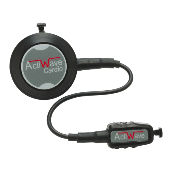
4mm studs found on ECG electrode pads. The choice of electrode pad will depend upon the application. The Actiwave Cardio can be comfortably worn for several days. For further information regarding electrode types and electrode placement, see section 6 of this manual. -
Page 9: Contraindications
Allows set-up, reading Cardio Dock CardioDock and charging of up to three Actiwave Cardio [08-733] STATUS STATUS STATUS devices only. USB interface for connection to PC (Cable supplied) Allows set-up, reading and charging of up to Combi Dock CombiDock four Actiwave 1, 2 or 4 devices plus one [08-727] STATUS... - Page 10 Actiwave User Guide - Issue 2.0.18 Page 10...
-
Page 11: Installing The Actiwave Software
In general, a faster processor will provide superior performance. Installing the Software Place the CD ROM into the drive; the Actiwave software installation menu should start automatically as shown below: If it does not start automatically (this functionality is sometimes disabled for security reasons) you will need to browse with Windows Explorer to view the CD ROM then double-click on the file ‘SplashScreen.exe’. -
Page 12: Updating The Software
Microsoft: Select ‘Continue Anyway’ (Please note that this is NOT a problem and just means that the Actiwave version of the driver software has not been assessed by Microsoft. In fact the actual drivers are Microsoft approved). -
Page 13: Running The Software For The First Time
The USB drivers must be installed before using the software for the first time Double clicking on the Actiwave icon on the desktop will start the software. If a dock is plugged in it should be detected and a view of it shown on screen. Three types of... -
Page 14: Connecting The Actiwave & Charging The Battery
3 Connecting the Actiwave & Charging the Battery Overview Before the Actiwave is used for data collection, the user must ensure that it is fully charged. A depleted battery may result in an incomplete recording as the Actiwave may shut down before data collection is complete. -
Page 15: Charging The Actiwave From The Pc
Actiwave devices are charged and their charge status is indicated by the LEDs on the dock. While the Actiwave is charging, the LED will be RED. When the Actiwave is charged, the LED will stay GREEN. Note that... -
Page 16: Charging Using The Mains Power Supply
Mains Power Supply The Actiwave Dock is supplied with a 5V USB mains power adaptor which is safety approved to EN60950-1 and EMI standard EN55022 (also FCC part 15, Class B). This adaptor is supplied with appropriate adaptors to suit mains outlets in most world regions. -
Page 17: Selecting An Actiwave And Viewing Status
Click anywhere within the highlighted area to select the Actiwave The selected Actiwave has a red border Right Click in this region... -
Page 18: Setting Up An Actiwave For A Recording
5 Setting up an Actiwave for a Recording Actiwave Set-up Select the required Actiwave from the main screen and then click ‘Set up Actiwave’. Note that the previous recording will then be erased. The setup options shown next are dependent on the unit type (Example shows an EEG/ECG 4). -
Page 19: Additional Actiwave Cardio Options
Completing the setup Click on the ‘OK’ button to store the setup to the Actiwave unit. The software will confirm when it is configured and show the programmed start time. The Actiwave can now be removed and attached to the subject. - Page 20 NOTE: Beginning a new set-up or erasing the Actiwave will result in loss of any existing stored data or set-up information – please ensure that any required data has been downloaded first.
-
Page 21: Preparing For An Actiwave Cardio Ecg Recording
6 Preparing for an Actiwave Cardio ECG Recording Electrode selection There is huge variety of electrode pads available to suit various applications. Signal quality is more dependent on skin preparation than pad type. Wear ability and adhesion are the main variables between pad types. recommend using your existing suppliers or searching the web to obtain the type of pads you require. -
Page 22: Electrode Positioning
Electrode Positioning The best ECG signals can usually be picked up by placing the round end of the Actiwave Cardio unit in a position midway between and below V1 and V2. The other electrode can be placed at V4 or V5. A position on the upper chest shown in the diagram below can also be used. -
Page 23: Use Of The Actiwave Cardio In Water
Important! In the European Union the Actiwave is not a medical device and is intended for research only. Please contact CamNtech UK for further clarification on suitability of application. -
Page 24: Preparing For A 3 Or 5 Channel Ecg Recording
EEG/ECG 2 device and a 5 lead ECG recording using an Actiwave EEG/ECG 4 device. The Actiwave ECG devices do not need a ground reference. In all these configurations the LL lead (Plain Black) should be connected to the common (C) of the Actiwave. - Page 25 Common (C) Yellow Green Blue Note: The Actiwave is not intended for use with infants of below 10kg in weight. Important! In the European Union the Actiwave is not a medical device and is intended for research only. Please contact CamNtech UK for further clarification on suitability of application.
-
Page 26: Preparing For An Emg Recording
Signal level & Sampling The level of EMG varies and the Actiwave unit has a high signal mode (8mV) and a low signal mode (500uV). The user selects which range to use when setting up. The expected signal level depends on the placement of the EMG electrodes. -
Page 27: Preparing For A Motion Recording
9 Preparing for a MOTION recording Mounting The Actiwave MOTION may be mounted in any required position on the subject. The quick release belts / mountings are available in several sizes to allow comfortable fitment to the waist, torso, upper arm, thigh or ankle. -
Page 28: 10 Downloading Data
Select the appropriate channel and then click on the ‘Read Actiwave’ button. The following window will appear: Notch Filter Mains pickup is not usually a problem with the Actiwave devices. They are connected only to the body and will not normally pick up signal from mains supplies. However,... -
Page 29: End Cut-Off Time
Having selected the appropriate options, click on the ‘OK’ button to download the Actiwave. Data is downloaded at 2Mbit per second from the Actiwave device. Even at this speed the data download may take a few minutes for a full memory. -
Page 30: The 'Download All' Option
The recorded data in the Actiwave device is not erased after download. It is only erased if the unit is set up again or erased using the erase all option. 10.3 The ‘Download All’ Option This function downloads data from all the Actiwave devices in the interface dock and stores them in different sequentially numbered files. -
Page 31: Free Edf File Viewers
Contact CamNtech for current pricing and information. Free EDF file viewers A number of free EDF viewers are available including Polyman, EDFbrowser, jEDF, OpenXDF Viewer, etc. CamNtech recommends Polyman, which is available in a free version from: http://www.edfplus.info/downloads/downloads.html. Many more advanced commercial packages are available for loading and analysing EDF files Actiwave User Guide - Issue 2.0.18... -
Page 32: Faq & Troubleshooting
Why do the first few seconds sometimes show a DC offset To conserve power the Actiwave unit powers down during the start delay. When it powers up to start storing data the amplifiers need a few seconds to settle. - Page 33 ‘A device which may be an Actiwave has been detected’: The battery in the Actiwave is below the level required to communicate. This message is a safety warning to prevent users of other CamNtech products attempting to use the wrong interface.
-
Page 34: Appendix 1 - Handling & Environmental Information
Appendix 1 - Handling & Environmental Information A1.1 Decontamination A1.2 Battery Care A1.3 Disposal Actiwave User Guide - Issue 2.0.18 Page 34... -
Page 35: A1.4 Environmental
A1.4 ENVIRONMENTAL A1.5 EMC Guidance & Declaration A1.5.1 Electromagnetic Emissions Actiwave User Guide - Issue 2.0.18 Page 35... -
Page 36: A1.5.2 Electromagnetic Immunity
A1.5.2 Electromagnetic Immunity Actiwave User Guide - Issue 2.0.18 Page 36... - Page 37 Example: For a typical mobile phone, the radiated RF will be in the 80MHz to 2.5GHz band and if the transmission power were 1W, the separation distance should be at least 2.33 meters. Actiwave User Guide - Issue 2.0.18 Page 37...
-
Page 38: Appendix 2 - Installing Usb Drivers Manually
Appendix 2 – Installing USB Drivers Manually Sometimes the automatic installation of drivers will not work, often because your computer has previously had similar, but different, drivers installed on it before and sometimes because of flaws in the Windows installation process. - Page 39 Select ‘Install from a list or specific location (Advanced)’ and click ‘Next’. Select ‘Don’t search. I will choose the driver to install.’ and click ‘Next’. The window on the next page should appear. Sometimes, windows will decide to display some other windows first, possibly appearing to lock up for a minute or two at one point.
- Page 40 Ignore the items in the list, and click ‘Have Disk…’ instead. Click on ‘Browse…’ and then use the standard file window to find the ‘USB drivers’ folder on the CD. Select ‘ftdibus.inf’ from this folder and click on ‘Open’. The window above will re-appear with a filename at the bottom.
- Page 41 If this window appears, click ‘Continue Anyway’. The underlying drivers are in fact tested and approved by Microsoft, but the certification is invalidated when they are configured to match our reader devices. When this window appears your drivers are installed. Actiwave User Guide - Issue 2.0.18 Page 41...
-
Page 42: Appendix 3 - Joining Edf Files
Appendix 3 – Joining EDF Files Introduction The Actiwave software installation contains a utility to allow the joining of EDF files produced by Actiwave devices. In the Start menu of the PC, locate the program ‘EDFjoin’ (this should be grouped within the Actiwave folder). - Page 43 Document Revision History Issue Issue Date Description Initiator From 16/05/08 First Issue 26/09/08 Updated to reflect current software modifications 20/05/09 Revisions to add appendices, improved formatting, additional safety and regulatory information added. 24/06/09 Further safety information added. 25/06/09 Further safety information added. 08/07/09 CE mark with NB number added to page 1 27/09/09...