Endress+Hauser MODBUS RS485 Operating Instructions Manual
Electromagnetic flow measuring system
Hide thumbs
Also See for MODBUS RS485:
- Operating instructions manual (80 pages) ,
- Operating instructions manual (92 pages) ,
- Operating instructions manual (84 pages)

Related Manuals for Endress+Hauser MODBUS RS485


Summary of Contents for Endress+Hauser MODBUS RS485
-
Page 1: Operating Instructions
Operating Instructions Proline Promag 53 MODBUS RS485 Electromagnetic Flow Measuring System BA117D/06/EN/12.09 71108004 Valid as of version V 3.04.XX (Device software) -
Page 3: Table Of Contents
3.1.3 Storage ......12 MODBUS RS485 communication ... . . 61 Installation conditions . - Page 4 Proline Promag 53 MODBUS RS485 Table of contents Maintenance ....93 Exterior cleaning ......93 Seals .
-
Page 5: Safety Instructions
• The device must be operated by persons authorized and trained by the facility's owner-operator. Strict compliance with the instructions in these Operating Instructions is mandatory. • Endress+Hauser is willing to assist in clarifying the chemical resistance properties of parts wetted by special fluids, including fluids used for cleaning. However, small changes in temperature, concentration or the degree of contamination in the process can result in changes to the chemical resistance properties. -
Page 6: Return
If the temperature of the fluid is high, implement sufficient measures to prevent burning or scalding. • The manufacturer reserves the right to modify technical data without prior notice. Your Endress+Hauser distributor will supply you with current information and updates to these Operating Instructions. Return •... -
Page 7: Identification
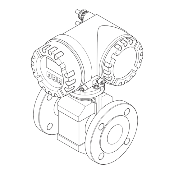
Proline Promag 53 MODBUS RS485 Identification Identification Device designation The flow measuring system consists of the following components: • Promag 53 transmitter • Promag W, Promag P or Promag H sensor Two versions are available: • Compact version: transmitter and sensor form a single mechanical unit. -
Page 8: Nameplate Of The Sensor
Identification Proline Promag 53 MODBUS RS485 2.1.2 Nameplate of the sensor PROMAG W Order Code: 53W1H-XXXXXXXXXXXX 12345678901 Ser.No.: ABCDEFGHJKLMNPQRST TAG No.: 1.0000/0000 0.2 CAL K-factor: DN100 DIN EN PN40 –20 °C ...+150°C/–4 ...+300°F °F Materials: 1.4435/316L EPD/MSÜ, R/B Electrodes: –20°C (–4°F)<Tamb<+60°C (+140°F) -
Page 9: Nameplate For Connections
Proline Promag 53 MODBUS RS485 Identification 2.1.3 Nameplate for connections active See operating manual passive Betriebsanleitung beachten normally open contact Observer manuel d'instruction normally closed contact XXXXXXXXXXX Ser.No.: L1/L+ Supply / Versorgung / N/L- Tension d'alimentation 26 = B (RxD/TxD-P) -
Page 10: Certificates And Approvals
EMC requirements of IEC/EN 61326. The measuring system described in these Operating Instructions therefore complies with the legal requirements of the EU Directives. Endress+Hauser confirms this by affixing the CE mark to it and by issuing the CE Declaration of Conformity. -
Page 11: Installation
Proline Promag 53 MODBUS RS485 Installation Installation Incoming acceptance, transport and storage 3.1.1 Incoming acceptance On receipt of the goods, check the following points: • Check the packaging and the contents for damage. • Check the shipment, make sure nothing is missing and that the scope of supply matches your order. -
Page 12: Storage
Installation Proline Promag 53 MODBUS RS485 Transporting flanged devices DN 300 (12") Use only the metal eyes on the flanges for transporting the device, lifting it and positioning the sensor in the piping. " Caution! Do not attempt to lift the sensor with the tines of a fork-lift truck beneath the metal casing. This would buckle the casing and damage the internal magnetic coils. -
Page 13: Installation Conditions
Proline Promag 53 MODBUS RS485 Installation Installation conditions 3.2.1 Dimensions The dimensions and installation lengths of the sensor and transmitter can be found in the "Technical Information" for the device in question. This document can be downloaded as a PDF file from www.endress.com. - Page 14 Installation Proline Promag 53 MODBUS RS485 Partially filled pipes Partially filled pipes with gradients necessitate a drain-type configuration. The Empty Pipe Detection function offers additional protection by detecting empty or partially filled pipes → ä 91. " Caution! Risk of solids accumulating. Do not install the sensor at the lowest point in the drain. It is advisable to install a cleaning valve.
-
Page 15: Orientation
Proline Promag 53 MODBUS RS485 Installation 3.2.3 Orientation An optimum orientation position helps avoid gas and air accumulations and deposits in the measuring tube. Promag, nevertheless, supplies a range of functions and accessories for correct measuring of problematic fluids: • Electrode Cleaning Circuitry (ECC) to prevent electrically conductive deposits in the measuring tube, e.g. -
Page 16: Inlet And Outlet Runs
Installation Proline Promag 53 MODBUS RS485 3.2.4 Inlet and outlet runs If possible, install the sensor in a location upstream of fittings such as valves, T-pieces, elbows, etc. Compliance with the following requirements for the inlet and outlet runs is necessary in order to ensure measuring accuracy. -
Page 17: Foundations, Supports
Proline Promag 53 MODBUS RS485 Installation 3.2.6 Foundations, supports If the nominal diameter is DN ≥ 350 (14"), mount the sensor on a foundation of adequate load- bearing strength. " Caution! Risk of damage. Do not support the weight of the sensor on the metal casing: the casing would buckle and damage the internal magnetic coils. -
Page 18: Nominal Diameter And Flow Rate
Installation Proline Promag 53 MODBUS RS485 3.2.8 Nominal diameter and flow rate The diameter of the pipe and the flow rate determine the nominal diameter of the sensor. The optimum velocity of flow is between 2 and 3 m/s (6.5 to 9.8 ft/s) The velocity of flow (v), moreover, has to be matched to the physical properties of the fluid: •... - Page 19 Proline Promag 53 MODBUS RS485 Installation Recommended flow (US units) Nominal diameter Promag W Promag P Promag H Min./max. full scale value (v ≈ 0.3 or 10 m/s) in [gal/min] [inch] " – – 0.015 to 0.5 " – –...
-
Page 20: Length Of Connecting Cable
Installation Proline Promag 53 MODBUS RS485 3.2.9 Length of connecting cable In order to ensure measuring accuracy, please comply with the following instructions when installing the remote version: • Secure the cable run or route the cable in an armored conduit. Movement of the cable can falsify the measuring signal, particularly if the fluid conductivity is low. -
Page 21: Installation
Proline Promag 53 MODBUS RS485 Installation Installation 3.3.1 Installing the Promag W sensor Note! Bolts, nuts, seals, etc. are not included in the scope of supply and must be supplied by the customer. The sensor is designed for installation between the two piping flanges: •... - Page 22 Installation Proline Promag 53 MODBUS RS485 Screw tightening torques (Promag W) Note the following points: • The tightening torques listed below are for lubricated threads only. • Always tighten the screws uniformly and in diagonally opposite sequence. • Overtightening the screws will deform the sealing faces or damage the seals.
- Page 23 Proline Promag 53 MODBUS RS485 Installation Nominal diameter EN (DIN) Max. tightening torque [Nm] [mm] Pressure rating Screws Hard rubber Polyurethane [bar] PN 16 20 × M 30 PN 25 20 × M 33 PN 6 20 × M 24 PN 10 20 ×...
- Page 24 Installation Proline Promag 53 MODBUS RS485 Promag W tightening torques for JIS Sensor Screws Max. tightening torque [Nm] Nominal diameter Pressure rating [mm] Hard rubber Polyurethane 4 × M 16 – 4 × M 16 – 4 × M 16 –...
- Page 25 Proline Promag 53 MODBUS RS485 Installation Sensor ANSI Screws Max. tightening torque [Nm] Nominal Pressure rating diameter [inch] [lbs] Hard rubber Polyurethane 16" Class 150 16 × 1" 18" Class 150 16 × 1 1/8" 20" Class 150 20 × 1 1/8"...
- Page 26 Installation Proline Promag 53 MODBUS RS485 Promag W tightening torques for AS 4087 Sensor AS 4087 Screws Max. tightening torque [Nm] Nominal diameter Pressure rating [mm] Hard rubber PN 16 4 × M 16 100 * PN 16 8 × M 16 PN 16 8 ×...
-
Page 27: Installing The Promag P Sensor
Proline Promag 53 MODBUS RS485 Installation 3.3.2 Installing the Promag P sensor " Caution! • The protective covers mounted on the two sensor flanges guard the PTFE lining, which is turned over the flanges. Consequently, do not remove these protection plates until immediately before the sensor is installed in the pipe. - Page 28 Installation Proline Promag 53 MODBUS RS485 Installing the high-temperature version (with PFA lining) The high-temperature version has a housing support for the thermal separation of sensor and transmitter. The high-temperature version is always used for applications in which high ambient temperatures are encountered in conjunction with high fluid temperatures.
- Page 29 Proline Promag 53 MODBUS RS485 Installation Promag P tightening torques for EN (DIN) Nominal diameter EN (DIN) Screws Max. tightening torque [Nm] Pressure rating [mm] [bar] PTFE PN 40 4 × M 12 – PN 40 4 × M 12 PN 40 4 ×...
- Page 30 Installation Proline Promag 53 MODBUS RS485 Promag P tightening torques for ANSI Nominal diameter ANSI Screws Max. tightening torque Pressure rating PTFE [lbs] [mm] [inch] [Nm] [lbf · ft] [Nm] [lbf · ft] ½" Class 150 4 × ½" –...
- Page 31 Proline Promag 53 MODBUS RS485 Installation Nominal diameter Screws Max. tightening torque [Nm] Pressure rating [mm] PTFE 8 × M 20 12 × M 22 12 × M 20 12 × M 22 12 × M 22 – 12 × M 24 –...
-
Page 32: Installing The Promag H Sensor
Particularly when using process connections made of plastic, it is essential that the sensor be mounted securely. A wall mounting kit for this purpose can be ordered separately as an accessory from Endress+Hauser (→ ä 94). a0004301 Fig. - Page 33 • Ground rings can be ordered separately from Endress+Hauser as accessories → ä 94. When placing the order, make certain that the ground ring is compatible with the material used for the electrodes.
- Page 34 Installation Proline Promag 53 MODBUS RS485 Welding the transmitter into the pipe (weld nipple) " Caution! Risk of electronics being destroyed. Please ensure that the welding system is not grounded via the sensor or transmitter. Secure the sensor using several welding points in the piping. A welding jig suitable for this purpose can be ordered separately as an accessory →...
-
Page 35: Turning The Transmitter Housing
Proline Promag 53 MODBUS RS485 Installation 3.3.4 Turning the transmitter housing Turning the aluminum field housing Warning! The rotating mechanism in devices with Ex d/de or FM/CSA Cl. I Div. 1 approval is different to that described here. The relevant procedure is described in the Ex-specific documentation. -
Page 36: Turning The Local Display
Installation Proline Promag 53 MODBUS RS485 3.3.5 Turning the local display Unscrew the electronics compartment cover from the transmitter housing. Press the latches on the side of the display module and pull the module out of the electronics compartment cover. -
Page 37: Installing The Wall-Mount Housing
Proline Promag 53 MODBUS RS485 Installation 3.3.6 Installing the wall-mount housing There are various ways of installing the wall-mount housing: • Mounted directly on the wall • Panel mounting (with separate mounting kit, accessories) → ä 38 • Pipe mounting (with separate mounting kit, accessories) → ä 38 "... - Page 38 Installation Proline Promag 53 MODBUS RS485 Panel mounting Prepare the opening in the panel as illustrated. Slide the housing into the opening in the panel from the front. Screw the fasteners onto the wall-mount housing. Place the threaded rods in the fasteners and screw them down until the housing is seated tightly against the panel wall.
-
Page 39: Post-Installation Check
Proline Promag 53 MODBUS RS485 Installation Post-installation check Perform the following checks after installing the measuring device in the pipe: Device condition/specifications Notes Is the device damaged (visual inspection)? → ä 116 Does the device correspond to specifications at the measuring point, including process temperature and pressure, ambient temperature, minimum fluid conductivity, measuring range, etc.? -
Page 40: Wiring
• Using cable type A and with a transmission rate of 115200 Baud, the maximum line length (segment length) of the MODBUS RS485 system is 1200 m. The total length of the spurs may not exceed a maximum of 6.6 m here. -
Page 41: Shielding And Grounding
Proline Promag 53 MODBUS RS485 Wiring 4.1.2 Shielding and grounding When planning the shielding and grounding for a fieldbus system, there are three important points to consider: • Electromagnetic compatibility (EMC) • Explosion protection • Safety of the personnel To ensure the optimum electromagnetic compatibility of systems, it is important that the system components and above all the cables, which connect the components, are shielded and that no portion of the system is unshielded. -
Page 42: Connecting The Remote Version
Wiring Proline Promag 53 MODBUS RS485 Connecting the remote version 4.2.1 Connecting the sensor Warning! • Risk of electric shock! Switch off the power supply before opening the device. Do not install or wire the device while it is connected to the power supply. Failure to comply with this precaution can result in irreparable damage to the electronics. - Page 43 Proline Promag 53 MODBUS RS485 Wiring Promag W, P 4 37 36 42 41 n.c. n.c. n.c. 4 37 42 41 A0011722 Fig. 28: Connecting the remote version of Promag W, P Wall-mount housing connection compartment Cover of the sensor connection housing...
- Page 44 Wiring Proline Promag 53 MODBUS RS485 Cable termination in remote version Promag W, Promag P Terminate the signal and coil current cables as shown in the figure below (Detail A). Fit the fine-wire cores with wire end ferrules (detail B: m = red ferrules, Ø 1.0 mm; n = white ferrules, Ø 0.5 mm) * Stripping for reinforced cables only "...
- Page 45 Proline Promag 53 MODBUS RS485 Wiring Cable termination in remote version Promag H Terminate the signal and coil current cables as shown in the figure below (Detail A). Fit the fine-wire cores with wire end ferrules (detail B: m = ferrules red, Ø 1.0 mm; n = ferrule white, Ø 0.5 mm) "...
-
Page 46: Cable Specifications
1 = Core, 2 = Core insulation, 3 = Core shield, 4 = Core jacket, 5 = Core reinforcement, 6 = Cable shield, 7 = Outer jacket Reinforced connecting cables As an option, Endress+Hauser can also deliver reinforced connecting cables with an additional, reinforcing metal braid. We recommend such cables for the following cases: •... -
Page 47: Connecting The Measuring Unit
Proline Promag 53 MODBUS RS485 Wiring Connecting the measuring unit 4.3.1 Terminal assignment " Caution! Only certain combinations of submodules (see Table) on the I/O board are permissible. The individual slots are marked and assigned to the following terminals in the connection compartment of the transmitter: •... - Page 48 Wiring Proline Promag 53 MODBUS RS485 (L–) B (RxD/TxD-P) (L+) A (RxD/TxD-N) A (RxD/TxD-N) B (RxD/TxD-P) + – + – + – – 20 21 22 23 24 25 26 27 – – N (L-) L1 (L+) a0002591 Fig. 31: Connecting the transmitter, Cable cross-section: max.
-
Page 49: Potential Equalization
Caution! When using process connections made of plastic, potential equalization must be guaranteed through the use of grounding rings → ä 33. The necessary grounding rings may be ordered separately as an accessory from Endress+Hauser (→ ä 94). 4.4.3 Connection examples for potential equalization... - Page 50 A0011893 The ground cable for flange-to-flange connections can be Fig. 33: Via the transmitter's ground terminal ordered separately as an accessory from Endress+Hauser. and the pipe flanges When using the measuring device in: • Plastic pipes • Isolating lined pipes This type of connection occurs when: •...
-
Page 51: Degree Of Protection
Proline Promag 53 MODBUS RS485 Wiring Degree of protection The devices fulfill all the requirements for IP 67 (NEMA 4X). Compliance with the following points is mandatory following installation in the field or servicing, in order to ensure that IP 67 protection (NEMA 4X) is maintained: •... -
Page 52: Post-Connection Check
Wiring Proline Promag 53 MODBUS RS485 Post-connection check Perform the following checks after electrical installation of the measuring device: Device condition and specifications Notes Are cables or the device damaged (visual inspection)? Electrical connection Notes Does the supply voltage match the specifications on the nameplate? -
Page 53: Operation
XXX.XXX.XX a0004397 Fig. 37: Methods of operating MODBUS RS485 devices Local display for device operation in the field (option) Configuration/operating program for operating via the service interface FXA 193 (e.g. FieldCare) Jumper/miniature switches for hardware settings (write protection, device address, address mode) -
Page 54: Local Display
Operation Proline Promag 53 MODBUS RS485 Local display 5.2.1 Display and operating elements The local display enables you to read important parameters directly at the measuring point or to configure your device using the "Quick Setup" or the function matrix. -
Page 55: Display (Operating Mode)
Proline Promag 53 MODBUS RS485 Operation 5.2.2 Display (operating mode) The display area consists of three lines in all; this is where measured values are displayed, and/or status variables (direction of flow, bar graph, etc.). You can change the assignment of display lines to variables at will in order to customize the display to suit your needs and preferences (→... -
Page 56: Icons
Operation Proline Promag 53 MODBUS RS485 5.2.4 Icons The icons which appear in the field on the left make it easier to read and recognize measured variables, device status, and error messages. Icon Meaning Icon Meaning System error Process error... -
Page 57: Controlling The Batching Processes Using The Local Display
Proline Promag 53 MODBUS RS485 Operation 5.2.5 Controlling the batching processes using the local display Filling processes can be carried out directly by means of the local display with the aid of the optional "(Batching)" software package (F-CHIP, accessories → ä 94). Therefore, the device can be fully deployed in the field as a "batch controller". -
Page 58: Brief Operating Instructions To The Function Matrix
Operation Proline Promag 53 MODBUS RS485 Brief operating instructions to the function matrix Note! • See the general notes → ä 59. • Function descriptions → see the "Description of Device Functions" manual HOME position → F → Entry into the function matrix O / S →... -
Page 59: General Notes
• If programming is disabled and the O/S keys are pressed in any function, a prompt for the code automatically appears on the display. • If "0" is entered as the customer’s code, programming is always enabled. • The Endress+Hauser service organization can be of assistance if you mislay your personal code. " Caution! Changing certain parameters such as all sensor characteristics, for example, influences numerous functions of the entire measuring system, particularly measuring accuracy. -
Page 60: Error Messages
Operation Proline Promag 53 MODBUS RS485 Error messages 5.4.1 Type of error Errors which occur during commissioning or measuring operation are displayed immediately. If two or more system or process errors occur, the error with the highest priority is the one shown on the display. -
Page 61: Modbus Rs485 Communication
System architecture The MODBUS RS485 is used to specify the functional characteristics of a serial fieldbus system with which distributed, digital automation systems are networked together. The MODBUS RS485 distinguishes between master and slave devices. - Page 62 Operation Proline Promag 53 MODBUS RS485 Master/slave communication A distinction is made between two methods of communication with regard to master/slave communication via MODBUS RS485: • Polling (request-response-transaction) The master sends a request telegram to one slave and waits for the slave's response telegram.
-
Page 63: Modbus Telegram
Proline Promag 53 MODBUS RS485 Operation 5.5.2 MODBUS telegram General The master-slave process is used for data exchange. Only the master can initiate data transmission. Following the prompt, the slave sends the master the necessary data as a response telegram or executes the command requested by the master. -
Page 64: Modbus Function Codes
Operation Proline Promag 53 MODBUS RS485 5.5.3 MODBUS function codes The function code determines which read, write and test operations should be executed by means of the MODBUS protocol. The measuring device supports the following function codes: Function Name in accordance... -
Page 65: Modbus Register Addresses
= read access via function codes 03, 04 or 23 write = write access via function codes 06, 16 or 23 MODBUS register address model The MODBUS RS485 register addresses of the measuring device are implemented in accordance with "MODBUS Applications Protocol Specification V1.1". Note! In addition to the specification mentioned above, systems are also deployed which work with a register address model in accordance with the "Modicon MODBUS Protocol Reference Guide -... - Page 66 Operation Proline Promag 53 MODBUS RS485 Data types The following data types are supported by the measuring device: • FLOAT (floating-point numbers IEEE 754) Data length = 4 bytes (2 registers) Byte 3 Byte 2 Byte 1 Byte 0 SEEEEEEE...
- Page 67 Proline Promag 53 MODBUS RS485 Operation Byte transmission sequence Byte addressing, i.e. the transmission sequence of the bytes, is not specified in the MODBUS specification. For this reason, it is important to coordinate the addressing method between the master and slave during commissioning. This can be configured in the measuring device by means of the "BYTE SEQUENCE"...
-
Page 68: Modbus Error Messages
The scan list can be configured by means of: The local display or a configuration program (e.g. FieldCare). The scan list is configured here by means of the function matrix: BASIC FUNCTION → MODBUS RS485 → SCAN LIST REG. 1 to SCAN LIST REG. 16 Endress+Hauser... - Page 69 Here, the scan list is configured via the register addresses 5001 to 5016. Scan list MODBUS configuration Configuration via Register address local operation / configuration program (BASIC FUNCTION → MODBUS RS485 →) (data type = Integer) 5001 SCAN LIST REG. 1 5002 SCAN LIST REG. 2 5003 SCAN LIST REG.
- Page 70 Operation Proline Promag 53 MODBUS RS485 Access to data via MODBUS The MODBUS master uses the register addresses 5051 to 5081 to access the data area of the auto- scan buffer. This data area contains the values of the device parameters defined in the scan list. For example, if the register 2009 was entered for volume flow in the scan list by means of the SCAN LIST REG.
- Page 71 1. Configuration of the scan list • With the local operation or a configuration program (via the function matrix): BASIC FUNCTION block → MODBUS RS485 function group → SCAN LIST REG. function → Entry of the address 2009 under SCAN LIST REG. 1 →...
- Page 72 Operation Proline Promag 53 MODBUS RS485 MODBUS RS485 Slave Master Auto-Scan Buffer Data Data Data Register Value Value Register Value 2009 4567.67 4567.67 5051 4567.67 56345.6 5053 56345.6 2610 56345.6 5055 6859 Scan List Register 2009 2610 6859 a0004415-en Fig. 48: With just one request telegram, the MODBUS master reads out the measured values via the auto-scan buffer of the measuring device.
-
Page 73: Operating Options
The Fieldcheck tester/simulator is used for testing flowmeters in the field. When used in conjunction with the "FieldCare" software package, test results can be imported into a database, printed and used for official certification. Contact your Endress+Hauser representative for more information. -
Page 74: Hardware Settings
Jumper for switching write protection on and off Write protection switched on = it is not possible to write to the device parameters via MODBUS RS485 Write protection switched off (factory setting) = it is possible to write to the device parameters via MODBUS RS485 Endress+Hauser... -
Page 75: Configuring The Device Address
The device address must always be configured for a MODBUS slave. The valid device addresses are in a range from 1 to 247. In a MODBUS RS485 network, each address can only be assigned once. If an address is not configured correctly, the device is not recognized by the MODBUS master. All measuring devices are delivered from the factory with the device address 247 and with the "software addressing"... -
Page 76: Configuring The Terminating Resistors
Proline Promag 53 MODBUS RS485 5.7.3 Configuring the terminating resistors It is important to terminate the MODBUS RS485 line correctly at the start and end of the bus segment since impedance mismatch results in reflections on the line which can cause faulty communication transmission. -
Page 77: Current Output Configuration
Proline Promag 53 MODBUS RS485 Operation 5.7.4 Current output configuration The current output is configured as "active" or "passive" by means of various jumpers on the current submodule. Warning! Risk of electric shock. Exposed components carry dangerous voltages. Make sure that the power supply is switched off before you remove the cover of the electronics compartment. -
Page 78: Relay Output Configuration
Operation Proline Promag 53 MODBUS RS485 5.7.5 Relay output configuration The relay contact can be configured as normally open (NO or make) or normally closed (NC or break) contacts by means of two jumpers on the pluggable submodule. This configuration can be called up at any time with the ACTUAL STATUS RELAY function (No. -
Page 79: Commissioning
Proline Promag 53 MODBUS RS485 Commissioning Commissioning Function check Make sure that all final checks have been completed before you start up your measuring point: • Checklist for "Post-installation check" → ä 39 • Checklist for "Post-connection check" → ä 52... -
Page 80: Quick Setup
Commissioning Proline Promag 53 MODBUS RS485 Quick Setup In the case of measuring devices without a local display, the individual parameters and functions must be configured via the configuration program, e.g. FieldCare. If the measuring device is equipped with a local display, all the important device parameters for standard operation, as well as additional functions, can be configured quickly and easily by means of the following Quick Setup menus. - Page 81 Proline Promag 53 MODBUS RS485 Commissioning 1002 XXX.XXX.XX Quick Setup Commission 2000 Language HOME-POSITION Defaults Selection Delivery Settings Acutal Settings pre-settings Selection Volume Mass Quit System units 0402 0420 Unit Unit Volume Flow Density 3001 0700 Value Unit Density Totalizer...
-
Page 82: Quick Setup "Pulsating Flow
Commissioning Proline Promag 53 MODBUS RS485 6.3.2 Quick Setup "Pulsating Flow" Note! The "Pulsating flow" Quick Setup is only available if the device has a current output or a pulse/ frequency output. Certain types of pump such as reciprocating, peristaltic and cam-type pumps, for example, create a flow characterized by severe periodic fluctuations . - Page 83 Proline Promag 53 MODBUS RS485 Commissioning Performing the "Pulsating flow" Quick Setup This Quick Setup menu guides you systematically through the setup procedure for all the device functions that have to be parameterized and configured for measuring pulsating flows. Note that this has no effect on values configured beforehand, such as measuring range, current range or full scale value.
- Page 84 Commissioning Proline Promag 53 MODBUS RS485 Note! • The display returns to the cell QUICK SETUP PULSATING FLOW (1003) if you press the Q key combination during parameter interrogation. • You can call up the Setup menu either directly from the "COMMISSIONING" Quick Setup menu or manually by means of the function QUICK SETUP PULSATING FLOW (1003).
-
Page 85: Quick Setup "Batching
Note! This function is only available when the additional "batching" software is installed in the measuring device (order option). You can order this software from Endress+Hauser as an accessory at a later date. → ä 94 This Quick Setup menu guides you systematically through the setup procedure for all the device functions that have to be parameterized and configured for batching operation. - Page 86 Commissioning Proline Promag 53 MODBUS RS485 XXX.XXX.XX Quick Setup HOME-POSITION 1005 Batching/Dosing 6402 ON-Value Low flow cut off 6603 System damping 6404 Pressure shock suppression 7200 Batch Selector 7201 Batch Name Batch 7203 Quantity 7204 Compensation Quantity Select Relay 1...
-
Page 87: Recommended Settings
Proline Promag 53 MODBUS RS485 Commissioning Recommended settings Quick Setup "Batching" HOME position → F → MEASURAND → O → QUICK SETUP → N → QUICK SETUP BATCHING (1005) Setting to be selected ( P ) Function No. Function name... -
Page 88: Quick Setup "Communication
Commissioning Proline Promag 53 MODBUS RS485 6.3.4 Quick Setup "Communication" To establish serial data transfer, various arrangements between the MODBUS master and MODBUS slave are required which have to be taken into consideration when configuring various functions. These functions can be configured quickly and easily by means of the "Communication" Quick Setup. - Page 89 → Repeatedly press and release the X key = Exit the function matrix step by step Note! The parameters described in the table can be found in the "MODBUS RS485" group of the "BASIC FUNCTION" block in the function matrix (see separate "Description of Device Functions" manual).
-
Page 90: Data Backup/Transmission
Commissioning Proline Promag 53 MODBUS RS485 6.3.5 Data backup/transmission Using the T-DAT SAVE/LOAD function, you can transfer data (device parameters and settings) between the T-DAT (exchangeable memory) and the EEPROM (device storage unit). This is required in the following instances: •... -
Page 91: Adjustment
Proline Promag 53 MODBUS RS485 Commissioning Adjustment 6.4.1 Empty-pipe/Full-pipe adjustment Flow cannot be measured correctly unless the measuring pipe is completely full. This status can be monitored at all times with the Empty Pipe Detection function: • EPD = Empty Pipe Detection (with the help of an EPD electrode) •... -
Page 92: Data Memory
Proline Promag 53 MODBUS RS485 Data memory At Endress+Hauser, the term HistoROM refers to various types of data storage modules on which process and measuring device data is stored. By plugging and unplugging such modules, device configurations can be duplicated onto other measuring devices to cite just one example. -
Page 93: Maintenance
Proline Promag 53 MODBUS RS485 Maintenance Maintenance No special maintenance work is required. Exterior cleaning When cleaning the exterior of measuring devices, always use cleaning agents that do not attack the surface of the housing and the seals. Seals The seals of the Promag H sensor must be replaced periodically, particularly in the case of molded seals (aseptic version). -
Page 94: Accessories
Accessories Proline Promag 53 MODBUS RS485 Accessories Various which can be ordered separately from Endress+Hauser, are available for the transmitter and the sensor. Detailed information about the concerned can be obtained from your Endress+Hauser service organization. Device-specific accessories Accessory Description Order code Transmitter for replacement or for stock. -
Page 95: Service-Specific Accessories
Proline Promag 53 MODBUS RS485 Accessories Service-specific accessories Accessory Description Order code Applicator Software for selecting and configuring flowmeters. DKA80 – * Applicator can be downloaded from the Internet or ordered on CD-ROM for installation on a local PC. Contact your Endress+Hauser representative for more information. -
Page 96: Troubleshooting
Troubleshooting Proline Promag 53 MODBUS RS485 Troubleshooting Troubleshooting instructions Always start troubleshooting with the checklist below, if faults occur after startup or during operation. The routine takes you directly to the cause of the problem and the appropriate remedial measures. -
Page 97: System Error Messages
Caution! In the event of a serious fault, a flowmeter might have to be returned to the manufacturer for repair. Important procedures must be carried out before you return a flowmeter to Endress+Hauser. → ä 115 Always enclose a duly completed "Declaration of contamination" form. You will find a preprinted blank of this form at the back of this manual. - Page 98 Troubleshooting Proline Promag 53 MODBUS RS485 Remedy (spare part → ä 107) MODBUS Device status message Cause (local display) Register: Register: 6859 6821 Data type: Data type: Integer String (18 byte) TRANSM. S: TRANSM. HW-DAT Transmitter DAT: 1. Check whether the T-DAT is correctly plugged...
- Page 99 Proline Promag 53 MODBUS RS485 Troubleshooting Remedy (spare part → ä 107) MODBUS Device status message Cause (local display) Register: Register: 6859 6821 Data type: Data type: Integer String (18 byte) COMMUNIC. I/O S: COMMUNICATION I/ No data reception between Check the BUS contacts.
- Page 100 Troubleshooting Proline Promag 53 MODBUS RS485 Remedy (spare part → ä 107) MODBUS Device status message Cause (local display) Register: Register: 6859 6821 Data type: Data type: Integer String (18 byte) 47 to 50 RANGE PULSE n S: PULSE RANGE Pulse output: 1.
- Page 101 Proline Promag 53 MODBUS RS485 Troubleshooting Remedy (spare part → ä 107) MODBUS Device status message Cause (local display) Register: Register: 6859 6821 Data type: Data type: Integer String (18 byte) 81 to 84 SIM. REL.OUT n S: SIM. RELAY n Simulation relay output active.
-
Page 102: Process Error Messages
Troubleshooting Proline Promag 53 MODBUS RS485 Process error messages Process errors can be defined as either "Fault" or "Notice" messages and can thereby be weighted differently. You can define messages in this way with the aid of the function matrix (→... - Page 103 Proline Promag 53 MODBUS RS485 Troubleshooting MODBUS Device status message Cause Remedy / spare part (local display) Register: Register: 6859 6821 Data type: Data type: Integer String (18 byte) >< BATCH QUANT. P: >< BATCH QUANTITY Underbatching: Underbatching: $: # 472 The minimum quantity was 1.
-
Page 104: Process Errors Without Messages
The following options are available for tackling problems of this nature: be rectified or some other • Request the services of an Endress+Hauser service technician fault not described above has arisen. If you contact our service organization to have a service technician sent out, please be ready to quote the following... -
Page 105: Response Of Outputs To Errors
Proline Promag 53 MODBUS RS485 Troubleshooting Response of outputs to errors Note! The failsafe mode of totalizers, current, pulse and frequency outputs can be customized by means of various functions in the function matrix. You will find detailed information on these procedures in the "Description of Device Functions"... - Page 106 Troubleshooting Proline Promag 53 MODBUS RS485 Failsafe mode of outputs and totalizers System/process error is present Positive zero return is activated Totalizer STOP Totalizer stops The totalizers are paused until the error is rectified. ACTUAL VALUE Fault is ignored, i.e. the totalizer continues to count according to the current flow value.
-
Page 107: Spare Parts
Note! You can order spare parts directly from your Endress+Hauser service organization by providing the serial number printed on the transmitter's nameplate. → ä 7 Spare parts are shipped as sets comprising the following parts: •... -
Page 108: Removing And Installing
Troubleshooting Proline Promag 53 MODBUS RS485 9.6.1 Removing and installing printed circuit boards Field housing Warning! • Risk of electric shock. Exposed components carry dangerous voltages. Make sure that the power supply is switched off before you remove the cover of the electronics compartment. - Page 109 Proline Promag 53 MODBUS RS485 Troubleshooting A0008241 Fig. 61: Field housing: removing and installing printed circuit boards Local display Screws of electronics compartment cover Ribbon cable (display module) Aperture for installing/removing boards Power unit board Amplifier board Electrode signal cable (sensor)
- Page 110 Troubleshooting Proline Promag 53 MODBUS RS485 Wall-mount housing Warning! • Risk of electric shock. Exposed components carry dangerous voltages. Make sure that the power supply is switched off before you remove the cover of the electronics compartment. • Risk of damaging electronic components (ESD protection). Static electricity can damage electronic components or impair their operability.
- Page 111 Proline Promag 53 MODBUS RS485 Troubleshooting a0004778 Fig. 62: Wall-mount housing: removing and installing printed circuit boards Housing cover Electronics module Ribbon cable (display module) Screws of electronics compartment cover Aperture for installing/removing boards Power unit board Amplifier board Electrode signal cable (sensor)
-
Page 112: Replacing The Device Fuse
Troubleshooting Proline Promag 53 MODBUS RS485 9.6.2 Replacing the device fuse Warning! Risk of electric shock. Exposed components carry dangerous voltages. Make sure that the power supply is switched off before you remove the cover of the electronics compartment. The main fuse is on the power supply board → å 63. -
Page 113: Replacing The Exchangeable Electrode
Proline Promag 53 MODBUS RS485 Troubleshooting 9.6.3 Replacing the exchangeable electrode The Promag W sensor (DN 350 to 2000; 14" to 78") can be supplied with optional exchangeable measuring electrodes. This design allows the measuring electrodes to be exchanged or cleaned under process conditions. - Page 114 Troubleshooting Proline Promag 53 MODBUS RS485 Removing the electrode Fitting the electrode Release the socket head cap screw (1) and remove Insert the new electrode (5) from underneath into the cap. the retaining cylinder (7). Ensure that the seals at the tip of the electrode are clean.
-
Page 115: Return
Costs incurred for waste disposal and injury (burns, etc.) due to inadequate cleaning will be charged to the owner-operator. The following steps must be taken before returning a flow measuring device to Endress+Hauser, e.g. for repair or calibration: • Always enclose a duly completed "Declaration of contamination" form. Only then can Endress+Hauser transport, examine and repair a returned device. -
Page 116: Technical Data
Technical data Proline Promag 53 MODBUS RS485 Technical data 10.1 Technical data at a glance 10.1.1 Application → ä 5 10.1.2 Function and system design Measuring principle Electromagnetic flow measurement on the basis of Faraday’s Law. → ä 7 Measuring system 10.1.3... - Page 117 Proline Promag 53 MODBUS RS485 Technical data MODBUS RS485: • MODBUS device type: slave • Address range: 1 to 247 • Functions codes supported: 03, 04, 06, 08, 16, 23 • Broadcast: supported with the function codes 06, 16, 23 •...
-
Page 118: Power Supply
Technical data Proline Promag 53 MODBUS RS485 10.1.5 Power supply → ä 40 Electrical connections Supply voltage 85 to 260 V AC, 45 to 65 Hz 20 to 55 V AC, 45 to 65 Hz 16 to 62 V DC... -
Page 119: Performance Characteristics
Proline Promag 53 MODBUS RS485 Technical data 10.1.6 Performance characteristics Reference operating To DIN EN 29104 and VDI/VDE 2641: conditions • Fluid temperature: +28 °C ± 2 K • Ambient temperature: +22 °C ± 2 K • Warm-up time: 30 minutes Installation: •... -
Page 120: Operating Conditions: Environment
Technical data Proline Promag 53 MODBUS RS485 10.1.8 Operating conditions: Environment Ambient temperature range Transmitter: • Standard: –20 to +60 °C (–4 to +140 °F) • Optional: –40 to +60 °C (–40 to +140 °F) Note! At ambient temperatures below –20 °C (–4 °F), the readability of the display may be impaired. -
Page 121: Operating Conditions: Process
Proline Promag 53 MODBUS RS485 Technical data 10.1.9 Operating conditions: Process Medium temperature range The permitted temperature depends on the lining of the measuring tube: Promag W • 0 to +80 °C (+32 to +176 °F) for hard rubber (DN 65 to 2000 / 2½ to 80") •... - Page 122 Technical data Proline Promag 53 MODBUS RS485 [°F] [°C] PTFE 40 60 80 120 140 160 [°C] 360 [°F] a0002671 Fig. 67: Remote versions (with PFA or PTFE lining) = ambient temperature; T = fluid temperature; HT = high-temperature version with insulation ➀...
- Page 123 Proline Promag 53 MODBUS RS485 Technical data • AS 2129 – Table E (DN 80, 100, 150 to 1200) • AS 4087 – PN 16 (DN 80, 100, 150 to 1200) Promag P • EN 1092-1 (DIN 2501) – PN 10 (DN 200 to 600) –...
- Page 124 Technical data Proline Promag 53 MODBUS RS485 Promag P Measuring tube lining: PTFE Promag P Resistance of measuring tube lining to partial vacuum: limit values for nominal diameter absolute pressure [mbar] ([psi]) at various fluid temperatures 25 °C 80° C 100 °C...
-
Page 125: 10.1.10 Mechanical Construction
Proline Promag 53 MODBUS RS485 Technical data 10.1.10 Mechanical construction Design / dimensions The dimensions and face-to-face length of the sensor and transmitter can be found in the separate "Technical Information" documentation for each device which can be downloaded in PDF format from www.endress.com. - Page 126 Technical data Proline Promag 53 MODBUS RS485 Promag P Note! The following weights apply to standard pressure ratings and without packaging material. Nominal Weights in [kg] for the Promag P diameter Compact version Remote version (without cable) Sensor Transmitter [mm]...
- Page 127 Proline Promag 53 MODBUS RS485 Technical data Weight (US units) Promag W Note! The following weights apply to standard pressure ratings and without packaging material. Nominal Weights in [lbs] for the Promag W diameter Compact version Remote version (without cable)
- Page 128 Technical data Proline Promag 53 MODBUS RS485 Promag P Note! The following weights apply to standard pressure ratings and without packaging material. Nominal Weights in [lbs] for the Promag P diameter Compact version Remote version (without cable) Sensor Transmitter [inch]...
- Page 129 Proline Promag 53 MODBUS RS485 Technical data Material Promag W • Transmitter housing: – Housing for compact version: powder-coated die-cast aluminum – Wall-mount housing: powder-coated die-cast aluminum • Sensor housing – DN 25 to 300: powder-coated die-cast aluminum – DN 350 to 2000: with protective coating •...
- Page 130 Technical data Proline Promag 53 MODBUS RS485 • Seals: as per DIN EN 1514-1 • Ground disks: 1.4435/316L, Alloy C-22, titanium, tantalum Promag H Transmitter housing: • Compact housing: powder-coated die-cast aluminum or stainless steel field housing (1.4301/316L) • Wall-mount housing: powder-coated die-cast aluminum •...
- Page 131 Proline Promag 53 MODBUS RS485 Technical data Process connection Promag W and Promag P Flange connections: • EN 1092-1 (DIN 2501) – DN ≤ 300 = form A – DN ≥ 350 = form B – DN 65 PN 16 and DN 600 PN 16 exclusively according to EN 1092-1 •...
-
Page 132: 10.1.11 Human Interface
Ex approval Information about currently available Ex versions (ATEX, FM, CSA, TIIS, IECEx, NEPSI etc.) can be supplied by your Endress+Hauser Sales Center on request. All explosion protection data are given in a separate documentation which is available upon request. - Page 133 Proline Promag 53 MODBUS RS485 Technical data Pressure device approval Measuring devices with a nominal diameter smaller than or equal to DN 25 correspond to Article 3(3) of the EC Directive 97/23/EC (Pressure Equipment Directive) and have been designed and manufactured according to good engineering practice.
-
Page 134: 10.1.13 Ordering Information
Various accessories are available for the transmitter and the sensor. These can be ordered separately from Endress+Hauser → ä 94. Note! For detailed information on specific order codes, please contact the Endress+Hauser service organization. 10.1.15 Documentation • Flow Measurement (FA005D/06) •... -
Page 135: Index
Cable specifications ......46 MODBUS RS485 ......40 Wall-mount housing. - Page 136 Proline Promag 53 MODBUS RS485 Index Measuring system ......7, 116 Measuring tube Galvanic isolation .
- Page 137 Transfer data ....... . 90 MODBUS RS485 ......47 Tightening torques Promag P .
- Page 138 Proline Promag 53 MODBUS RS485 Index Vibration resistance ......120 Vibrations ........16 Measures to prevent vibrations.
- Page 139 Erklärung zur Kontamination und Reinigung Please reference the Return Authorization Number (RA#), obtained from Endress+Hauser, on all paperwork and mark the RA# clearly on the outside of the box. If this procedure is not followed, it may result in the refusal of the package at our facility.
- Page 140 www.endress.com/worldwide BA117D/06/EN/12.09 71108004 FM+SGML6.0 ProMoDo...