Endress+Hauser Liquistation CSF48 Operating Instructions Manual
Automatic sampler for liquid media
Hide thumbs
Also See for Liquistation CSF48:
- Operating instructions manual (268 pages) ,
- Operation and setting (188 pages) ,
- Brief operating instructions (76 pages)

Related Manuals for Endress+Hauser Liquistation CSF48


Summary of Contents for Endress+Hauser Liquistation CSF48
- Page 1 Operating Instructions Liquistation CSF48 Automatic sampler for liquid media Commissioning BA00443C/07/EN/16.12 71185263 Valid as of: Softwareversion 01.03.00...
- Page 2 Overview of documentation Operating Instructions The Operating Instructions are split into several parts: Commissioning (BA00443C) • All steps that you have to carry out once only during initial commissioning • Descriptions of menus – Basic settings – Display/Operation • Technical data Operation &...
- Page 3 Application manual (SD01068C) • Software and configuration examples • FAQs • Program examples Operating Instructions BA00443C, BA00463C, BA00464C, BA00467C and SD01068C can be found in all the available languages on the CD-ROM enclosed.
-
Page 4: Table Of Contents
Liquistation CSF48 Table of contents Safety instructions... 5 Commissioning ... .56 Designated use ..... . 5 Function check . -
Page 5: Safety Instructions
Safety instructions Designated use The Liquistation CSF48 is a stationary sampler for liquid media. The samples are taken discontinuously using a vacuum or peristaltic pump, distributed to sampling containers and cooled. The sampler is designed for use in the following applications: •... -
Page 6: Return
The product must be returned if it is in need of repair or a factory calibration, or if the wrong product was ordered or delivered. Legal specifications require Endress+Hauser, as an ISO-certified company, to follow certain procedures when handling returned products that are in contact with the medium. -
Page 7: Notes On Safety Conventions And Icons
Liquistation CSF48 Safety instructions Notes on safety conventions and icons 1.5.1 Warnings The structure, signal words and safety colors of the signs comply with the specifications of ANSI Z535.6 ("Product safety information in product manuals, instructions and other collateral materials"). -
Page 8: Identification
Identification Liquistation CSF48 Identification Device designation 2.1.1 Nameplate Nameplates can be found: • On the inside of the upper door • On the packaging (adhesive label, portrait format) The nameplate provides you with the following information on your device: • Manufacturer ID •... -
Page 9: Scope Of Delivery
Liquistation CSF48 Identification Scope of delivery The scope of delivery comprises: • 1 Liquistation CSF48 with: – The ordered bottle configuration – Optional hardware • Accessories kit with: – Connection fitting for suction line with various angles (straight, 90˚), Allen key (for version with vacuum pump only) •... -
Page 10: Device Description
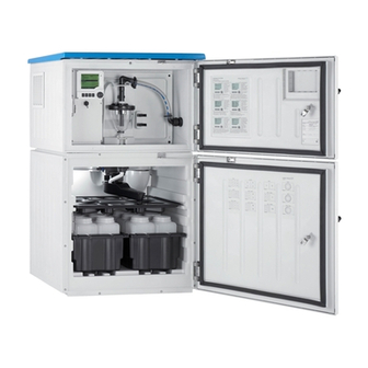
Liquistation CSF48 Device description A complete sampling unit comprises: Liquistation CSF48 for open channels, with the following depending on the version ordered: • Controller with display, soft keys and navigator • Vacuum or peristaltic pump for sampling • Plastic (PE) or glass sample bottles for sample preservation •... - Page 11 Sample bottles, e.g. 2 x 12 PE 1 liter bottles Bottle trays (depending on the sample bottles selected) Distribution plate (depending on the sample bottles selected) Distribution arm a0015868 Fig. 3: Example of a Liquistation CSF48 with the CSA420 sampling assembly Direct sample feeder pipe Endress+Hauser...
- Page 12 Device description Liquistation CSF48 Example of the Samplefit CSA420 sampling assembly with flange connection a0015913 Fig. 4: Samplefit CSA420 sampling assembly with flange connection DN50, PP Example of the Samplefit CSA420 sampling assembly with Triclamp connection a0015914 Fig. 5: Samplefit CSA420 sampling assembly with Triclamp connection DN50, DIN 32676...
-
Page 13: Installation
Liquistation CSF48 Installation Installation Incoming acceptance, transport, storage ► Make sure the packaging is undamaged! ► Inform the supplier about any damage to the packaging. Keep the damaged packaging until the matter has been settled. ► Make sure the contents are undamaged! ►... -
Page 14: Installation Conditions
Installation Liquistation CSF48 Installation conditions 4.2.1 Dimensions a0013080 Fig. 6: Dimensions of plastic version of Liquistation CSF48 without/with stand Suction line connection Endress+Hauser... - Page 15 Liquistation CSF48 Installation a0013082 Fig. 7: Dimensions of stainless steel version of Liquistation CSF48 without/with stand Suction line connection Endress+Hauser...
- Page 16 Liquistation CSF48 4.2.2 Mounting location For version with pump a0011693 Fig. 8: Mounting conditions for Liquistation CSF48 for open channels Correct The suction line must be routed with a downward slope to the sampling point. Incorrect The sampler should never be mounted in a place where it is exposed to aggressive gases.
- Page 17 For version with sampling assembly a0015886 Fig. 9: Installation conditions for Liquistation CSF48 with Samplefit CSA420 sampling assembly Note the following when installing the sampling assembly in pipelines: • The best installation location is in the ascending pipe (position 2). Installation is also possible in the horizontal pipe (position 1).
- Page 18 Installation Liquistation CSF48 • Make sure air can circulate freely through the side panels of the housing. Do not mount the sampler directly against a wall. Allow at least 150 mm (5.9") between the wall and the sampler on the left and right-hand sides.
- Page 19 Liquistation CSF48 Installation 4.2.4 Connection for sampling for version with pump • Maximum suction height: Vacuum pump: standard 6 m (20 ft), optional 8 m (26 ft) Peristaltic pump: standard 8 m (26 ft) • Maximum hose length: 30 m (98 ft) •...
-
Page 20: Erecting The Sampler
Installation Liquistation CSF48 Erecting the sampler 4.3.1 Connecting the suction line from the side for version with pump Observe the installation conditions when mounting the sampler. Route the suction line from the sampling point to the sampler. Screw the suction line onto the suction line connection of the sampler. - Page 21 Liquistation CSF48 Installation Connecting the suction line in the version with the vacuum pump Unscrew the thread adapter nut (item 3). Unscrew the hose gland (item 4) from the side panel. Fit the hose gland in the fixing clamp (item 2) as illustrated.
- Page 22 Installation Liquistation CSF48 Connecting the suction line in the version with the peristaltic pump Unscrew the thread adapter nut (item 3) and the hose gland (item 4) from the side panel. Unscrew the small thread adapter nut (item 1) and remove the hose.
- Page 23 • Connect the black compressed air lines from the sampler (item 6) to the connections on the sampling assembly. • In the case of the Liquistation CSF48 version that does not feature an internal compressor, connect the black compressed air hose (item 5) to the external compressed air supply.
-
Page 24: Sampling With A Flow Assembly
Installation Liquistation CSF48 Sampling with a flow assembly The sample is taken directly from the flow assembly which is installed in the sampler stand. The flow assembly is used when sampling in pressurized systems, e.g.: • Containers located at a higher level •... -
Page 25: Post-Installation Check
Liquistation CSF48 Installation a0013458 Fig. 18: Example: Sampling from pressure piping Ball valve 1 Valve 2 Flow assembly Use the ball valve 1 to set the flow rate to 1000 l/h-1500 l/h. When the sampling cycle begins, you can use one of the relay outputs to control and open valve 2. The medium flows through the pipe and the flow assembly into the outflow. -
Page 26: Wiring
Wiring Liquistation CSF48 Wiring WARNING Device is energized Incorrect wiring can result in injury or fatality ► The electrical connection must only be carried out by a certified electrician. ► Technical personnel must have read and understood the instructions in this manual and must adhere to them. - Page 27 Liquistation CSF48 Wiring 5.1.3 Removing the rear panel of the dosing compartment Open the dosing compartment door to remove the rear panel of the dosing compartment. a0012803 a0012826 Fig. 19: Screw above the dosing compartment Fig. 20: Lift up the top rear panel and pull it back to remove it...
- Page 28 Wiring Liquistation CSF48 5.1.5 Removing the cover on the power unit WARNING Device is energized Incorrect wiring can result in injury or fatality ► Make sure the device is disconnected from the power source before you remove the cover of the power unit.
- Page 29 Liquistation CSF48 Wiring 5.1.6 Power supply terminal assignment The power supply is connected via plug-in terminals. Connect the ground to one of the ground connections. Rechargeable batteries are available as an option (for battery type see section Technical Data). Fuses are available as an option (see section Technical Data).
-
Page 30: Terminal Assignment For Input/Output Signals
Wiring Liquistation CSF48 5.1.7 Cable terminals 1. Insert a suitable screwdriver into the opening of the terminal clip (square opening) as far as the screwdriver can go. a0003602 Fig. 25: Opening the terminal 2. Insert the terminated end of the cable into the terminal opening (round opening). -
Page 31: Optional Sensor Inputs, Current Outputs And Relays
Liquistation CSF48 Wiring Optional sensor inputs, current outputs and relays 5.3.1 Connection compartment in the controller housing The controller housing has a separate connection compartment. Release the 6 housing screws to open the connection compartment: a0012843 Fig. 28: Release 6 housing screws with a Phillips... - Page 32 Wiring Liquistation CSF48 5.3.2 Slot and port coding with optional additional modules a0016633-en Fig. 30: Slot and port coding of hardware and on-screen display The electronic configuration follows a modular concept: • Several slots are available for electronics modules. • These slots are numbered consecutively in the housing. Slots 0 and 1 are always reserved for the basic module.
- Page 33 Liquistation CSF48 Wiring • The outputs and relays are named after their function, e.g. "Current output", and are displayed in ascending order with the slot and port numbers Example, å 30: – If "Current output 2:1" is displayed, this means: Slot 2 (e.g.
- Page 34 Wiring Liquistation CSF48 5.3.4 SYS basic module a0013172 Fig. 32: SYS basic module SD card slot Connection cable to sampler controller Slot for the display cable Power connection Service interface Internal device connection. Do not disconnect the connector! 5.3.5 E basic module a0016535 Fig.
- Page 35 Liquistation CSF48 Wiring a0016537 Fig. 34: E basic module wiring diagram 5.3.6 Plug-in terminals for Memosens and PROFIBUS/RS485 connections a0012691 a0012692 a0012693 Fig. 35: Press the screwdriver against the Fig. 36: Insert the cable until the limit Fig. 37: Remove the screwdriver (closes...
- Page 36 Wiring Liquistation CSF48 5.3.7 All other plug-in terminals a0012694 a0012695 a0012696 Fig. 38: Insert the screwdriver (opens the Fig. 39: Insert the cable until the limit Fig. 40: Remove the screwdriver (closes terminal) stop the terminal) 5.3.8 Sensor types with Memosens protocol...
- Page 37 Liquistation CSF48 Wiring 5.3.9 Sensor connection Before you connect a sensor to the controller, you must first route it via the back panel to the controller housing towards the front. See the "Removing the rear panel of the dosing compartment" and the "Removing the rear panel of the sampling compartment"...
- Page 38 Wiring Liquistation CSF48 Connecting the end sleeves of the sensor cable to the E basic module The outer shield of the cable is grounded by means of the metal gland on the left of the E basic module. a0016356 Fig. 43: Terminal strip 5.3.10 Connecting sensors with Memosens protocol...
- Page 39 Liquistation CSF48 Wiring a0016197 Fig. 46: Sensors with and without additional supply voltage at sensor module 2DS 5.3.11 Connecting additional outputs and relays WARNING Module not covered No shock protection. Danger of electric shock! ► If you are modifying or extending your hardware, always fill the slots from top to bottom. Do not leave any gaps.
- Page 40 Wiring Liquistation CSF48 Current outputs Module 2AO Module 4AO a0016179 a0015759 a0016178 a0015760 Fig. 47: Module front Fig. 48: Wiring diagram Fig. 49: Module front Fig. 50: Wiring diagram Relays Module 2R Module 4R a0016181 a0015758 a0016182 a0015757 Fig. 51: Module front Fig.
- Page 41 Liquistation CSF48 Wiring Example: Connecting the compressed air cleaning unit 71072583 for CAS40D a0016371 Fig. 55: Connecting the compressed air cleaning unit for CAS40D Endress+Hauser...
- Page 42 Wiring Liquistation CSF48 Example: Connecting the injector cleaning unit Chemoclean CYR10 a0016372 Fig. 56: Connecting the injector cleaning unit CYR10 External power supply Cleaner to spray head Container with cleaner Motive water 2 to 12 bar (30 to 180 psi)
-
Page 43: Connecting Digital Communication
Liquistation CSF48 Wiring Connecting digital communication 5.4.1 Module 485 a0016173 a0015762 Fig. 57: Bus connections on module 485 Fig. 58: Wiring diagram for module 485 Optional to supply power to an external terminating resistor for bus termination LEDs on front of module... - Page 44 Wiring Liquistation CSF48 DIP switches on front of module Factory setting Assignment 1-128 Bus address (--> "Commissioning/Communication") Write protection: "ON" = configuration not possible via the bus, only via local operation Service Only for service, not to be used by the operator 5.4.2 Bus termination...
-
Page 45: Sampler Controller
Liquistation CSF48 Wiring Sampler controller The connections for the sampler controller are in the controller housing, see section "Connection compartment in the controller housing". 5.5.1 Analog inputs and binary inputs/outputs a0012988 Fig. 61: Position of the terminals Analog inputs 1 and 2 Binary inputs/outputs 5.5.2 Analog inputs... - Page 46 Wiring Liquistation CSF48 a0015214 Fig. 63: Connection example analog input with two-wire transmitter, e.g. Liquiline M CM42 a0015212 Fig. 64: Connection example analog input with four-wire transmitter, e.g. Prosonic S FMU90 5.5.3 Binary inputs a0013381 Fig. 65: Assignment of binary inputs 1 and 2...
- Page 47 Liquistation CSF48 Wiring a0013404 Fig. 66: Connection example binary input with external voltage source When connecting to an internal voltage source, use the terminal connection on the rear of the dosing chamber. The connection is located on the lower terminal strip (on the far left, + and -), see the "Power supply terminal assignment"...
- Page 48 Wiring Liquistation CSF48 5.5.5 Binary outputs with relay option a0016343 Fig. 69: Relays Binary output 1 Binary output 2 The left relay is activated with binary output 1, while the right relay is activated by binary output 2. a0016348 Fig. 70: Connection example for binary output with relay...
-
Page 49: Remote Operation
Liquistation CSF48 Wiring Remote operation 5.6.1 Via HART (e.g. via HART modem and FieldCare) a0015608 Fig. 71: HART via modem Base-L, or -E device module: current output 1 with HART HART modem for connecting to PC, e.g. Commubox FXA191 (RS232) or FXA195... - Page 50 Wiring Liquistation CSF48 5.6.3 Via Modbus RS485 a0015875 Fig. 73: Modbus RS485 Terminating resistor 5.6.4 Via ethernet/Web server/Modbus TCP a0015876 Fig. 74: Modbus TCP and / or ethernet Endress+Hauser...
-
Page 51: Post-Connection Check
Liquistation CSF48 Wiring Post-connection check WARNING Wiring errors Incorrect wiring puts the safety of people and the measuring point at risk. The manufacturer does not accept any responsibility for errors that result from failure to comply with the instructions in this manual. -
Page 52: Operation
Operation Liquistation CSF48 Operation Display and operating elements 6.1.1 Overview Navigator (jog/shuttle and press/hold function) Soft keys (function depends on the menu) Display (red background in the event of an a0013350-en Fig. 75: Overview of operation error) 6.1.2 Display Menu path and/or device designation Status display Assignment of the soft keys, e.g. -
Page 53: Operation Concept
Liquistation CSF48 Operation Operation concept a0013353-en a0013354-en Fig. 77: Pressing the soft key: selecting the menu directly Fig. 78: Turning the navigator: moving the cursor in the menu a0013355-en a0013356-en Fig. 79: Pressing the navigator: launching a function Fig. 80: Turning the navigator: selecting a value (e.g. from a... -
Page 54: Configuration Options
Operation Liquistation CSF48 Configuration options 6.3.1 Display only • You can only read the values but cannot change them. • Typical read-only values are: sensor data and system information • Example: Menu/Setup/Inputs/../Sensor type 6.3.2 Picklists • You receive a list of options. - Page 55 Liquistation CSF48 Operation 6.3.5 Customized text • You are assigning an individual designation. • Enter a text. You can use the characters in the editor for this purpose (upper-case and lower-case letters, numbers and special characters). • Using the soft keys, you can: –...
-
Page 56: Commissioning
Commissioning Liquistation CSF48 • Example: Menu/Setup/Inputs/pH/Medium comp. Commissioning Function check WARNING Incorrect connection, incorrect supply voltage Safety risks for staff and incorrect operation of the device ► Check that all connections have been established correctly in accordance with the wiring diagram. -
Page 57: Switching On The Unit
Liquistation CSF48 Commissioning a0016322 a0016323 a0016324 Fig. 83: Valid PROFIBUS address 67 Fig. 84: Valid Modbus address 195 Fig. 85: Invalid address 255 Order configuration, software addressing is enabled, software address configured at the factory: PROFIBUS 126, Modbus Address configuration via software: --> BA00464C "Operation & settings"... - Page 58 Commissioning Liquistation CSF48 7.3.3 Display settings Path: Menu/Display/Operation Function Options Info Contrast 5 ... 95 % Adjust the screen settings to suit your working environment. Backlight="Automatic" Backlight Options The backlighting is switched off automatically after a short • On time if a button is not pressed. It switches back on again as •...
-
Page 59: Display
Liquistation CSF48 Commissioning Path: Menu/Display/Operation Function Options Info Source of data Options Select a binary-, current- or temperature input as the data • Binary input source. • Current inputs • Temperature • Memosens sensor input (optional) • Fieldbus signals • Mathematical functions... - Page 60 Commissioning Liquistation CSF48 Primary value of the selected channel The name of the channel, the sensor type connected and the current primary value are shown on the display. Primary and secondary measured value of the selected channel The name of the channel, the sensor type connected and the current primary and secondary value are shown on the display.
-
Page 61: Basic Setup
Liquistation CSF48 Commissioning Icon Location Description At measured value The displayed measured value is simulated If two or more diagnostics messages occur simultaneously, only the icon for the message with the highest priority is shown on the display. 7.4.3 Assignment views Assignment views, e.g. -
Page 62: Sampling Programs
Commissioning Liquistation CSF48 Sampling programs 7.6.1 Differences between the types of program The following chart provides an overview of the differences between the Basic, Standard and Advanced program types: Basic: single program Sampling program (1) activation immediate Program stop Program start:... - Page 63 Liquistation CSF48 Commissioning 7.6.2 Manual sampling • Manual sampling is triggered by the "MAN" soft key. This pauses any program currently running. • The current bottle configuration and the current sample volume are displayed. The distributor position and sample volume can be changed.
-
Page 64: Technical Data
Technical data Liquistation CSF48 • Example: Technical data Input 8.1.1 Input types • 2 analog inputs • 2 binary inputs • 1 to 4 digital inputs for sensors with Memosens protocol (optional) 8.1.2 Measured variable --> Documentation of the connected sensor Temperature inputs 8.2.1 Measuring range... -
Page 65: Binary Input, Passive
Liquistation CSF48 Technical data Binary input, passive 8.3.1 Span 12 to 30 V, galvanically isolated 8.3.2 Signal characteristics Minimum pulse width: 100 ms Analog input, passive/active 8.4.1 Span 0/4 to 20 mA, galvanically isolated 8.4.2 Accuracy ±0.5 % of measuring range Output 8.5.1 Output signal... -
Page 66: Current Output, Active
Technical data Liquistation CSF48 PROFIBUS DP Signal encoding EIA/TIA-485, PROFIBUS-DP-compliant as per IEC 61158 Data transmission rate 9.6 kBd, 19.2 kBd, 45.45kBd, 93.75 kBd, 187.5 kBd, 500 kBd, 1.5 MBd, 6 MBd, 12 MBd Galvanic isolation Connector Spring terminal (max. 1.5 mm), bridged internally (T-function) -
Page 67: Relay Outputs
Liquistation CSF48 Technical data 8.7.3 Signal on alarm Adjustable, as per NAMUR Recommendation NE 43 • In the measuring range 0 to 20 mA (HART is not available with this measuring range): Error current from 0 to 23 mA • In measuring range 4 to 20 mA: Error current from 2.4 to 23 mA... -
Page 68: Protocol-Specific Data
Technical data Liquistation CSF48 • Relay coupled with binary output – Max. 5 A with 230 V AC, cos = 0.8 to 1 Min. 100,000 switching cycles – Max. 5 A with 24 V DC, L/R = 0 to 1 ms Min. - Page 69 Liquistation CSF48 Technical data 8.9.2 PROFIBUS DP Manufacturer ID Device type 155D (CM44x), 155C (CSFxx) Profile version 3.02 Device master files (GSD) www.products.endress.com/profibus Device Integration Manager DIM Output 16 AI blocks, 8 DI blocks Input 8 AO blocks, 4 DO blocks Supported features •...
-
Page 70: 8.10 Power Supply
Technical data Liquistation CSF48 8.9.5 Web server TCP port Supported features • Remote-controlled device configuration • Device configuration saved/restored • Logbook export (file formats: CSV, FDM) • Web server accessed via DTM or Internet Explorer 8.10 Power supply 8.10.1 Electrical connection See "Wiring"... -
Page 71: 8.11 Performance Characteristics
Liquistation CSF48 Technical data 8.10.6 Power failure • Power supply (optional): 2 x 12 V, 7.2 Ah, with additional charge controller Replace the rechargeable batteries with type Panasonic LC-R127R2PG1. • Real-time clock: lithium battery, type CR2032 8.11 Performance characteristics 8.11.1 Sampling methods Vacuum pump/peristaltic pump/sampling assembly: •... - Page 72 Technical data Liquistation CSF48 8.11.4 Repeatability • Vacuum pump: 5 % • Peristaltic pump: 5 % • Sampling assembly: 5 % 8.11.5 Intake speed > 0.5 m/s (> 1.6 ft/s) for ≤13 mm (1/2") ID, in accordance with EN 25667, ISO 5667 >...
-
Page 73: 8.12 Environment
Liquistation CSF48 Technical data 8.12 Environment 8.12.1 Ambient temperature range • With temperature control unit: -20 to 40 ˚C (0 to 100 ˚F) • Without temperature control unit: 0 to 40 ˚C (32 to 100 ˚F) 8.12.2 Storage temperature -20 to 60 ˚C (0 to 140 ˚F) 8.12.3 Electromagnetic compatibility... -
Page 74: 8.14 Mechanical Construction
Technical data Liquistation CSF48 8.13.3 Medium properties Liquistation with vacuum pump Capacitance level measurement used for: • Media that tend to create a lot of foam or contain fats and grease • Media with a conductivity < 30 μS/cm Liquistation with peristaltic pump •... - Page 75 Liquistation CSF48 Technical data 8.14.3 Material The plastic material polystyrene VO can discolor if exposed directly to sunlight. The plastic material ASA+PC V0 is recommended for outdoor installations where a sun guard is not used. The discoloring does not affect the function and operation of the device.
- Page 76 Technical data Liquistation CSF48 Wetted parts Vacuum pump Peristaltic pump Sampling assembly Suction line connection Plastic PP Purge connection Plastic PP Select the process seal depending on the application. Viton is recommended for standard applications with aqueous samples. Vacuum pump only Pneumatikschläuche...
-
Page 77: Index
Liquistation CSF48 Index Accessories......19 Electromagnetic compatibility ....6 Approvals . - Page 78 Liquistation CSF48 Opening Warnings....... 7 Controller housing ..... 31 Wiring.
- Page 79 Liquistation CSF48 Endress+Hauser...
- Page 80 BA00443C/07/EN/16.12 FM+SGML 6.0...