Endress+Hauser Liquistation CSF48 Operating Instructions Manual
Automatic sampler for liquid media
Hide thumbs
Also See for Liquistation CSF48:
- Operating instructions manual (268 pages) ,
- Operation and setting (188 pages) ,
- Brief operating instructions (76 pages)

Related Manuals for Endress+Hauser Liquistation CSF48


Summary of Contents for Endress+Hauser Liquistation CSF48
- Page 1 Operating Instructions Liquistation CSF48 Automatic sampler for liquid media Commissioning BA443C/07/EN/14.11 71129544 Valid as of: Software version 01.02.00...
- Page 2 Overview of documentation The Operating Instructions are split into several parts: Commissioning (BA443C) • All steps that you have to carry out once only during initial commissioning • Descriptions of menus – Basic settings – Display/Operation • Technical data Operation & configuration (BA464C) •...
-
Page 3: Table Of Contents
Technical data ... . 44 Input ......44 Endress+Hauser... -
Page 4: Safety Instructions
Safety instructions Safety instructions Designated use The Liquistation CSF48 is a stationary sampler for liquid media. The samples are takendiscontinuously using a vacuum or peristaltic pump, distributed to sampling containers andcooled. The sampler is designed for use in the following applications: •... -
Page 5: Return
Operating Instructions. Return If you need to return your instrument, contact your regional Endress+Hauser Sales or Service Representative to get the local return procedure. To find your local contact, check our web site at www.endress.com and select your region. -
Page 6: Identification
• On the front page of these Operating Instructions • In the delivery papers To find out the version of your device, enter the order code indicated on the nameplate in the search screen at the following address: www.products.endress.com/order-ident Endress+Hauser... -
Page 7: Scope Of Delivery
Standards for Water Monitoring Equipment Part 1, Version 2.1 dated November 2009"; Certificate no.: Sira MC100176/00. cCSAus The product meets the requirements of "Class 8721 05, laboratory equipment, electrical; Class 8721 85, laboratory equipment, electrical, certified to US standards"; Certificate no.: 2318018. Endress+Hauser... -
Page 8: Device Description
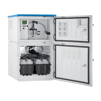
Distribution plate (depending on the sample bottles selected) Distribution arm Vacuum system, e.g. dosing system with a0011690 Fig. 1: Example of a Liquistation CSF48, version with vacuum pump conductive sample sensor Controller Window (optional) Dosing compartment door Suction line connection Sampling compartment door Sample bottles, e.g. -
Page 9: Installation
• If you have any questions, please contact your supplier or your local sales center. NOTICE The top of the sampler may be damaged or torn by incorrect transportation ► Always use a lifting truck or a fork-lift to transport the sampler. Never lift the sampler by the top. Endress+Hauser... -
Page 10: Installation Conditions
Installation Installation conditions 4.2.1 Dimensions a0013080 Fig. 3: Dimensions of plastic version of Liquistation CSF48 without/with stand Suction line connection Endress+Hauser... - Page 11 Installation a0013082 Fig. 4: Dimensions of stainless steel version of Liquistation CSF48 without/with stand Suction line connection Endress+Hauser...
- Page 12 Allow at least 150 mm (5.91") between the wall and the sampler on the left and right-hand sides. • Do not mount the sampler directly over the inlet channel of a municipal wastewater treatment plant. Endress+Hauser...
- Page 13 Installation 4.2.3 Mechanical connection Foundation plan a0012761 Fig. 6: Foundation plan Fasteners (4 x M10) Cable inlet Outlet for condensate and overflow > DN 50 Sample supply from below > DN 80 - - - Dimensions of Liquistation Endress+Hauser...
-
Page 14: Erecting The Sampler
4.3.1 Connecting the suction line from the side Observe the installation conditions when mounting the sampler. Route the suction line from the sampling point to the sampler. Screw the suction line onto the suction line connection of the sampler. Endress+Hauser... - Page 15 Remove the drain plug from the hose gland located at the back of the sampler base. As illustrated, guide the suction line upwards and through the opening towards the front. Gland for the suction line Suction line a0013704 Fig. 7: Sample supply from below Endress+Hauser...
- Page 16 Unscrew the thread adapter nut (item 3) and the hose gland (item 4) from the side panel. Unscrew the small thread adapter nut (item 1) and remove the hose. Connect the suction line from below as illustrated. Insert the dummy plugs supplied. Endress+Hauser...
-
Page 17: Sampling With A Flow Assembly
• Pumping with external pumps The flow rate should be 1000 to 1500 l/h. Flow assembly inlet: ¾" Sample connection Flow assembly outlet: 1¼" a0013127 Fig. 12: Flow assembly The outlet of the flow assembly must be unpressurized (e.g. drain, open channel). Endress+Hauser... -
Page 18: Post-Installation Check
• Make sure the suction line is securely fitted to the sampler. • Perform a visual inspection to ensure the suction line is routed correctly from the sampling point to the sampler. • Make sure the distribution arm is correctly mounted. Endress+Hauser... -
Page 19: Wiring
• Analog, signaling and transmission cables: e.g. LiYY 10x0.34 mm The terminal connection is located under an additional protective cover in the upper rear section of the device. For this reason, the rear panel of the device must be removed to connect the power supply prior to commissioning. Endress+Hauser... - Page 20 5.1.4 Removing the rear panel of the sampling compartment a0012825 a0012824 Fig. 16: Remove the bolts on the bottom left and right on the Fig. 17: Push up the lower rear panel to remove it rear of the dosing compartment Endress+Hauser...
- Page 21 ► Make sure the device is disconnected from the power source before you remove the cover of the power unit. a0012831 Fig. 18: Removing the cover on the power unit Release the screw with an Allen key (5 mm) Remove the cover of the power unit from the front Endress+Hauser...
- Page 22 Fuses are available as an option (see section Technical Data). Use rechargeable batteries only. a0013237 Fig. 19: Terminal assignment Assignment for 230 V: 100 ... 120 V/200 ... 240 V AC ±10 % Assignment for 24 V DC +15/-9 % Rechargeable batteries (optional) Internal voltage source Fuses Endress+Hauser...
-
Page 23: Terminal Assignment For Input/Output
• 2 binary signals > 100 ms pulse or edge • Signals of digital sensors with Memosens protocol (optional) Output signals • 2 binary signals > 1 s pulse or edge The controller must be opened to connect the signal cables and the sensor cables. Endress+Hauser... -
Page 24: Optional Sensor Inputs, Current Outputs And Relays
The controller housing has a separate connection compartment. Release 6 housing screws toopen the display cover: a0012843 Fig. 23: Release 6 housing screws with a Phillips screwdriver to open the display cover a0013238 Fig. 24: Controller with L basic module, opened L basic module Sampler controller Endress+Hauser... - Page 25 SD card slot Fuse (T4.0A) Slot for the display cable Alarm relay connection Service interface Power supply for digital fixed cable sensors with Connections for 2 Memosens sensors Memosens protocol Current outputs Internal device connection. Do not disconnect the connector! Endress+Hauser...
- Page 26 (opens the terminal) stop the terminal) After connection, make sure that every cable end is securely in place. Terminated cable ends, in particular, tend to come loose easily if they have not been correctly inserted as far as possible. Endress+Hauser...
- Page 27 Inductively measuring conductivity sensors Digital sensors with additional Fixed cable • Turbidity sensors power supply • Nitrate sensors • Optical oxygen sensors 5.3.7 Sensor connection If possible, only use terminated genuine cables. a0003350 Fig. 34: Memosens data cable CYK10 Endress+Hauser...
- Page 28 The outer shield of the cable is grounded by means of the metal gland on the left of the L basicmodule. a0013451 Fig. 35: Connecting CYK10 sensor cable a0013497 Fig. 36: Connecting sensor with Memosens protocol with additional supply voltage Endress+Hauser...
-
Page 29: Sampler Controller
The connections for the sampler controller are in the controller housing, see section "Connection compartment in the controller housing". 5.4.1 Analog inputs and binary inputs/outputs a0012988 Fig. 37: Position of the terminals Analog inputs 1 and 2 Binary inputs/outputs Endress+Hauser... - Page 30 Analog input for active devices (4-wire transmitter) In + Gnd terminals (123/124 or 223/224) a0015214 Fig. 39: Connection example analog input with two-wire transmitter, e.g. Liquiline M CM42 a0015212 Fig. 40: Connection example analog input with four-wire transmitter, e.g. Prosonic S FMU90 Endress+Hauser...
- Page 31 Connect the cable cores to terminals "+" and "-" (bottom terminal block, left), see section Power supply terminal assignment. 5.4.4 Binary outputs a0013382 Fig. 43: Assignment of binary outputs 1 and 2 Binary output 1 (145/146) Binary output 2 (245/246) Endress+Hauser...
-
Page 32: Post-Connection Check
Hydraulic connection 10. Is the suction line connected along with the suction strainer? 11. Is the suction line routed at a gradient without any loops? 12. Are all the sample connections leak-tight? 13. Are sample bottles in the sampling compartment? Endress+Hauser... -
Page 33: Operation
Menu path and/or device designation Status display Assignment of the soft keys, e.g. ESC: escape or abortion of a sampling process MAN: manual sample ?: help, if available OFF: switches the device to standby or aborts a0013241-en Fig. 46: Display (example) a program Endress+Hauser... -
Page 34: Operation Concept
Fig. 49: Pressing the navigator: launching a function Fig. 50: Turning the navigator: selecting a value (e.g. from a list) a0013357-en a0013358-en Fig. 51: Pressing the navigator: accepting the new value Fig. 52: Result: new setting is accepted Endress+Hauser... -
Page 35: Configuration Options
• You know that the item in question is an action if it is preceded by the following symbol: • Examples of typical actions include: – Starting a sampling program – Starting manual sampling – Saving or loading configurations • Example: Menu/Manual sampling/Start sampling Endress+Hauser... - Page 36 – Cancel your entries without saving the data ( – Delete the character in front of the cursor ( – Move the cursor back one position ( – Finish your entries and save ( • Example: Menu/Setup/General settings/Device tag Endress+Hauser...
-
Page 37: Commissioning
Press the Navigator button to reactivate the display. Screen rotation Options If "Automatic" is selected, the single-channel measured value • Manual display switches from one channel to the next every second. • Automatic Factory setting Manual User definable screens Endress+Hauser... - Page 38 The sampling program has been started and the device takes a sample as per the set parameters. Display "Inactive": No sampling program has been started, or a program that was running has been stopped. Start Action The selected sampling program is started. Endress+Hauser...
-
Page 39: Basic Setup
Software path in main menu Current output x:y Outputs Setup/Outputs/Current output x:y Alarm relay Outputs Setup/Outputs/Alarm relay Relais x:y Outputs Setup/Outputs/Relais x:y Limit switches Additional functions Setup/Additional functions/Limit switches Diagnostics settings General settings Setup/General settings/Extended setup/Diagnostics settings Cleaning Additional functions Setup/Additional functions/Cleaning Endress+Hauser... - Page 40 • The current bottle configuration and the current sample volume are displayed. The distributor position and sample volume can be changed. • A new screen is displayed indicating the progress of the sampling process. • After manual sampling a running program can be displayed by the "ESC" soft key. • Example: Endress+Hauser...
- Page 41 7."Multiple bottles": same sample in several bottles. "Start condition" immediately or time-delayed. "Stop condition" after the last sample or continuous operation. 10. Pressing the "SAVE" soft key saves the program and ends data entry. 11. Example: "Menu/Setup/Sampling programs/Setup program/New/Basic" Endress+Hauser...
-
Page 42: Display
In the first 3 modes, you can switch between channels by turning the navigator. In addition to having an overview of all the channels, in the 4th mode you can also select a value and press the navigator to see more details for the value. You can also find your user-defined screens in this mode. Endress+Hauser... - Page 43 "Assignment views", e.g. Channel assignment view, appear as the last function in many sections of the menu. You can use this function to see what actuators or functions are connected to a sensor channel. The assignments appear in hierarchical order. Endress+Hauser...
-
Page 44: Technical Data
±0.5 Kelvin Binary input, passive 8.3.1 Span 12 to 30 V, galvanically isolated 8.3.2 Signal characteristics Minimum pulse width: 100 ms Analog input, passive/active 8.4.1 Span 0/4 to 20 mA, galvanically isolated 8.4.2 Accuracy ±0.5 % of measuring range Endress+Hauser... -
Page 45: Output
Error current from 2.4 to 23 mA • Factory setting for both measuring ranges: 21.5 mA 8.6.4 Load Max. 500 Ω 8.6.5 Output voltage Max. 24 V 8.6.6 Cable type Recommended: shielded cable 8.6.7 Cable cross-section Max. 2.5 mm (14 AWG) Endress+Hauser... -
Page 46: Relay Outputs
Min. 100,000 switching cycles Minimum load (typical) • Min. 100 mA with 5 V DC • Min. 1 mA with 24 V DC • Min. 5 mA with 24 V AC • Min. 1 mA with 230 V AC Endress+Hauser... -
Page 47: Power Supply
• Device version with 24 V DC power supply: 240 W 8.8.6 Power failure • Power supply (optional): 2 x 12 V, 7.2 Ah, with additional charge controller Replace the rechargeable batteries with type Panasonic LC-R127R2PG1. • Real-time clock: lithium battery, type CR2032 Endress+Hauser... -
Page 48: Performance Characteristics
> 0.6 m/s (> 1.9 ft/s) for 10 mm (3/8") ID, in accordance with Ö 5893 (Austrian standard), US EPA 8.9.6 Suction height • Vacuum pump: 6 m (20 ft) or 8 m (26 ft), depending on the version • Peristaltic pump: Max. 8 m (26 ft) Endress+Hauser... -
Page 49: 8.10 Environment
Interference emission and interference immunity as per EN 61326-1: 2006, class A for industry 8.10.4 Electrical safety In accordance with EN 61010-1, protection class I, environment ≤ 2000 m (6500 ft) above MSL; pollution degree 2 8.10.5 Relative humidity 10 to 95%, not condensing Endress+Hauser... -
Page 50: 8.11 Process
Plastic version with refrigeration 101 kg (223 lbs) Plastic version without refrigeration and with 105 kg (232 lbs) fixed castor frame Stainless steel version with refrigeration 118 kg (260 lbs) Stainless steel version with stand and refrigeration 146 kg (322 lbs) Endress+Hauser... - Page 51 Distribution arm cover Plastic PE Distribution plate Plastic PS Composite container/bottles Plastic PE, glass (depending on version) Suction line Plastic PVC, EPDM (depending on version) Suction line connection Plastic PP Pneumatics Vacuum pump only Pneumatikschläuche Silicone Air-Manager housing Air-Manager sealing Silicone Endress+Hauser...
- Page 52 Vacuum pump only Pump head Aluminium, anodized Pump membrane EPDM 8.12.4 Process connections • Vacuum pump: Suction line ID 10 mm (3/8"), 13 mm (1/2"), 16 mm (5/8") or 19 mm (3/4") • Peristaltic pump: Suction line ID 10 mm (3/8") Endress+Hauser...
-
Page 53: Index
Load ........45 Dimensions ......10, 50 Endress+Hauser... - Page 54 Material ....... 51 Relay outputs......46 Measured variable.
- Page 55 Endress+Hauser...
- Page 56 BA443C/07/EN/14.11...