Endress+Hauser Liquistation CSF48 Brief Operating Instructions
Automatic sampler for liquid media
Hide thumbs
Also See for Liquistation CSF48:
- Operating instructions manual (268 pages) ,
- Operation and setting (188 pages) ,
- Brief operating instructions (56 pages)
Table of Contents
Advertisement
Quick Links
KA01165C/07/EN/08.22-00
71588419
2022-09-16
Products
Brief Operating Instructions
Liquistation CSF48
Automatic sampler for liquid media
These instructions are Brief Operating Instructions; they are
not a substitute for the Operating Instructions pertaining to
the device.
Detailed information on the device can be found in the
Operating Instructions and in the other documentation
available at:
• www.endress.com/device-viewer
• Smart phone/tablet: Endress+Hauser Operations App
Solutions
Services
Advertisement
Table of Contents

Related Manuals for Endress+Hauser Liquistation CSF48


Summary of Contents for Endress+Hauser Liquistation CSF48
- Page 1 These instructions are Brief Operating Instructions; they are not a substitute for the Operating Instructions pertaining to the device. Detailed information on the device can be found in the Operating Instructions and in the other documentation available at: • www.endress.com/device-viewer • Smart phone/tablet: Endress+Hauser Operations App...
- Page 2 Liquistation CSF48 Order code: XXXXX-XXXXXX Ser. no.: XXXXXXXXXXXX Ext. ord. cd.: XXX.XXXX.XX Serial number www.endress.com/deviceviewer Endress+Hauser Operations App A0040778 Endress+Hauser...
-
Page 3: Table Of Contents
Liquistation CSF48 Table of contents Table of contents About this document ............. . 4 Warnings . -
Page 4: About This Document
About this document Liquistation CSF48 About this document Warnings Structure of information Meaning This symbol alerts you to a dangerous situation. DANGER Failure to avoid the dangerous situation will result in a fatal or serious injury. Causes (/consequences) If necessary, Consequences of non- compliance (if applicable) ‣... -
Page 5: Documentation
About this document Documentation The following manuals complement these Brief Operating Instructions and are available on the product pages on the Internet: • Operating Instructions Liquistation CSF48, BA00443C • Device description • Commissioning • Operation • Software description (excluding sensor menus; these are described in a separate manual - see below) •... -
Page 6: Basic Safety Instructions
Intended use Liquistation CSF48 is a stationary sampler for liquid media. The samples are taken discontinuously using a vacuum pump or peristaltic pump or sampling assembly and are then distributed into sampling containers and refrigerated. -
Page 7: Operational Safety
Liquistation CSF48 Basic safety instructions Operational safety Before commissioning the entire measuring point: Verify that all connections are correct. Ensure that electrical cables and hose connections are undamaged. Do not operate damaged products, and protect them against unintentional operation. Label damaged products as defective. -
Page 8: Product Safety
Basic safety instructions Liquistation CSF48 Product safety 2.5.1 State-of-the-art technology The product is designed to meet state-of-the-art safety requirements, has been tested, and left the factory in a condition in which it is safe to operate. The relevant regulations and international standards have been observed. -
Page 9: Product Description
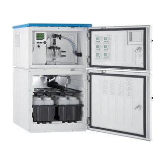
Liquistation CSF48 Product description Product description Product design Depending on the version, a complete sampling unit for open channels comprises: • Controller with display, soft keys and navigator • Vacuum or peristaltic pump for sampling • PE or glass sample bottles for sample preservation •... - Page 10 Product description Liquistation CSF48 Controller Window (optional) Dosing compartment door Suction line connection Sampling chamber door Sample bottles, e.g. 2 x 12 bottles, PE, 1 liter Bottle trays (depending on sample bottles selected) Distribution plate (depending on sample bottles selected)
- Page 11 Distribution arm 10 Direct supply line for sample A0024319 3 Example of a Liquistation CSF48 with CSA420 sampling assembly Example of Samplefit CSA420 sampling assembly with flange connection A0024320 4 Samplefit CSA420 sampling assembly with flange connection DN50, PP...
-
Page 12: Equipment Architecture
Product description Liquistation CSF48 A0024321 5 Samplefit CSA420 sampling assembly with Triclamp connection DN50, DIN 32676 Equipment architecture 3.2.1 Slot and port assignment – – 12,5V 3,3V A0045689 6 Slot and port assignment of hardware and presentation on the display... - Page 13 Liquistation CSF48 Product description The electronics configuration follows a modular concept: • There are several slots for electronics modules. These are referred to as "slots". • These slots are numbered consecutively in the housing. Slots 0 and 1 are always reserved for the base module.
-
Page 14: Terminal Diagram
Product description Liquistation CSF48 Terminal diagram The unique terminal name is derived from: Slot no. : Port no. : Terminal Example, NO contact of a relay Device with inputs for digital sensors, 4 current outputs and 4 relays • Base module BASE2-E (contains 2 sensor inputs, 2 current outputs) •... -
Page 15: Incoming Acceptance And Product Identification
Liquistation CSF48 Incoming acceptance and product identification Incoming acceptance and product identification Incoming acceptance Verify that the packaging is undamaged. Notify the supplier of any damage to the packaging. Keep the damaged packaging until the issue has been resolved. -
Page 16: Storage And Transport
Transport the sampler using a lifting truck or forklift. Do not lift the sampler by the roof. Lift it in the middle between the top and bottom sections. Scope of delivery The scope of delivery comprises: • 1 Liquistation CSF48 with: • The ordered bottle configuration • Optional hardware • Accessories kit For peristaltic or vacuum pump: Hose adapter for suction line with various angles (straight, 90°), Allen screw (for version... - Page 17 Liquistation CSF48 Incoming acceptance and product identification ‣ If you have any queries: Please contact your supplier or local sales center. Endress+Hauser...
-
Page 18: Mounting
Mounting Liquistation CSF48 Mounting Mounting requirements 5.1.1 Dimensions 625 (24.6) 471 (18.5) 753 (29.7) 355 (14.0) 125 (4.9) 816 (32.1) 625 (24.6) 471 (18.5) 753 (29.7) 355 (14.0) 125 (4.9) 816 (32.1) A0025857 8 Dimensions of Liquistation, plastic version, without/with stand. Unit of measurement mm (in) - Page 19 Liquistation CSF48 Mounting 624 (24.6) 467 (18.4) 743 (29.3) 355 (14.0) 125 (4.9) 816 (32.1) 624 (24.6) 467 (18.4) 743 (29.3) 355 (14.0) 125 (4.9) 816 (32.1) A0024423 9 Dimensions of Liquistation, stainless steel version, without/with stand. Unit of...
- Page 20 Mounting Liquistation CSF48 5.1.2 Installation site For version with sample pump A0024411 10 Liquistation mounting conditions Mounting conditions Route the suction line with a downward gradient to the sampling point. Never mount the sampler in a place where it is exposed to aggressive gases.
- Page 21 A0024412 11 Installation conditions for Liquistation CSF48 with Samplefit CSA420 sampling assembly Note the following when installing the sampling assembly in a pipe: • The best installation location is in the ascending pipe (pos. 2). Installation is also possible in the horizontal pipe (pos.
- Page 22 Mounting Liquistation CSF48 • Protect the device against strong magnetic fields. • Make sure air can circulate freely at the side panels of the cabinet. Do not mount the device directly against a wall. Allow at least 150 mm (5.9") from the wall to the left and right.
- Page 23 Liquistation CSF48 Mounting 5.1.4 Connection for sample intake and for version with sample pump • Maximum suction height: • Vacuum pump: standard 6 m (20 ft) option 8 m (26 ft) • Peristaltic pump: standard 8 m (26 ft) • Maximum hose length: 30 m (98 ft) •...
-
Page 24: Setting Up The Device
Mounting Liquistation CSF48 Setting up the device 5.2.1 Connecting the suction line at the side on version with pump When setting up the device, take the installation conditions into account. Route the suction line from the sampling point to the device. - Page 25 Liquistation CSF48 Mounting A0013704 13 Sample supply from below Gland for the suction line Suction line Endress+Hauser...
- Page 26 Mounting Liquistation CSF48 Connecting the suction line on version with vacuum pump A0013708 A0013707 15 Suction line connected from below 14 Connecting the suction line from the side (as- delivered state) Hose Fixing clip for hose gland Thread adapter nut...
- Page 27 Liquistation CSF48 Mounting Connecting the suction line on version with peristaltic pump A0013705 A0013706 16 Connecting the suction line from the side (as- 17 Suction line connected from below delivered state) Small thread adapter nut Hose Thread adapter nut...
-
Page 28: Sampling With A Flow Assembly
Connect the black compressed air lines from the sampler (item 6) to the connections on the sampling assembly. In the case of the Liquistation CSF48 version without an internal compressor, connect the black compressed air hose (item 5) to the external compressed air supply. -
Page 29: Post-Installation Check
Liquistation CSF48 Mounting The max. flow rate should be 1000 to 1500 l/h. Flow assembly inflow: ¾" Sampling connection Flow assembly outflow: 1¼" A0013127 19 Connections on flow assembly 71119408 The outlet of the flow assembly must be unpressurized (e.g. drain, open channel). - Page 30 Mounting Liquistation CSF48 Allow the sampler to rest for at least 12 hours after setup and before switching it on. Otherwise you may cause damage to the climate control module. Endress+Hauser...
-
Page 31: Electrical Connection
Liquistation CSF48 Electrical connection Electrical connection WARNING Device is live! Incorrect connection may result in injury or death! ‣ The electrical connection may be performed only by an electrical technician. ‣ The electrical technician must have read and understood these Operating Instructions and must follow the instructions contained therein. -
Page 32: Connecting The Sensors
Electrical connection Liquistation CSF48 Connecting the sensors 6.1.1 Connection compartment in the controller housing A0042244 A0012843 1 E base module Sampler controller The controller housing has a separate connection Display cover open, version with base module E compartment. Release the six cover screws to open the connection compartment: ‣... - Page 33 Liquistation CSF48 Electrical connection 6.1.2 Description of base module SYS BASE2-SYS Status A0042245 21 Base module SYS (BASE2-SYS) SD card slot Slot for display cable Ethernet interface Connecting cable to sampler controller Voltage connection Service interface Internal device connection, do not disconnect the plug.
- Page 34 Electrical connection Liquistation CSF48 6.1.3 Description of base module E A0042273 22 BASE2-E Power supply for digital fixed cable sensors with Memosens protocol SD card slot Slot for display cable Ethernet interface Service interface Connections for 2 Memosens sensors...
- Page 35 Liquistation CSF48 Electrical connection 6.1.4 Sensor types with Memosens protocol Sensors with Memosens protocol Sensor types Sensor cable Sensors Digital sensors without With plug-in • pH sensors additional internal power connection and • ORP sensors supply inductive signal • Combined sensors transmission •...
- Page 36 Electrical connection Liquistation CSF48 6.1.6 Sensor connection ‣ Guide the sensor cable via the rear panel to the controller housing towards the front. → 51 and → 52 A0016360 23 Gland to the controller Only use terminated original cables where possible.
-
Page 37: Connecting The Sampler Controller
Liquistation CSF48 Electrical connection Connecting the ferrules of the sensor cable to the base module E ‣ Ground the outer shield of the cable via the metal gland to the left of the base module E. A0028930 25... - Page 38 Electrical connection Liquistation CSF48 6.2.1 Wiring the analog inputs and binary inputs/outputs 125 123 124 225 223 224 191 192 291292 145 146 245 246 A0042282 26 Position of the terminals Analog inputs 1 and 2 Binary inputs/outputs 6.2.2...
- Page 39 Liquistation CSF48 Electrical connection CSXxx CMxx A0028652 28 With two-wire transmitter, e.g. Liquiline M CM42 CSXxx FMU90 A0028653 29 With four-wire transmitter, e.g. Prosonic S FMU90 6.2.3 Binary inputs A0013381 30 Assignment of binary inputs 1 and 2...
- Page 40 Electrical connection Liquistation CSF48 When connecting to an internal voltage source, use the terminal connection on the rear of the dosing compartment. The connection is located on the lower terminal strip (on the far left, + and -), (→ 53) 6.2.4...
-
Page 41: Connecting The Signal Transmitter To The Alarm Relay
Liquistation CSF48 Electrical connection Connecting the signal transmitter to the alarm relay A0016343 34 Relay Binary output 1 Binary output 2 The left relay is activated with binary output 1, while the right relay is activated by binary output 2. -
Page 42: Connecting The Communication
Electrical connection Liquistation CSF48 Connecting the communication 6.4.1 Wiring cables at cable terminals Plug-in terminals for Memosens and PROFIBUS/RS485 connections ‣ ‣ Insert the cable until the limit stop. ‣ Press the screwdriver against the Remove the screwdriver (closes the clip (opens the terminal). - Page 43 Liquistation CSF48 Electrical connection 36 Press the screwdriver 37 Insert the cable until the 38 Remove the screwdriver against the clip (opens limit stop (closes the terminal) the terminal) 6.4.2 Module 485DP 128/SW Service DGND Termi- nation A0050400 ...
- Page 44 Electrical connection Liquistation CSF48 LEDs on front of module Designation Color Description Power Supply voltage is applied and module is initialized. Bus failure Bus failure System failure Device error Communication PROFIBUS message sent or received. Bus termination • Off = No termination •...
- Page 45 Liquistation CSF48 Electrical connection Terminal Modbus RS485 DGND LEDs on front of module Designation Color Description Power Supply voltage is applied and module is initialized. Bus failure Bus failure System failure Device error Communication Modbus message sent or received. Bus termination •...
- Page 46 Electrical connection Liquistation CSF48 6.4.4 Module ETH 128/SW Service 44 Wiring 43 Module diagram LEDs on front of module Designation Color Description RJ45 LNK/ACT • Off = Connection is not active • On = Connection is active • Flashing = Data transmission...
- Page 47 Liquistation CSF48 Electrical connection 6.4.5 Bus termination There are 2 ways to terminate the bus: 1. Internal termination (via DIP switch on module board) "OFF" "ON" 45 DIP switch for internal termination ‣ Using a suitable tool such as a tweezer, move all four DIP switches to the "ON" position.
-
Page 48: Connecting Additional Inputs, Outputs Or Relays
Electrical connection Liquistation CSF48 Connecting additional inputs, outputs or relays WARNING Module not covered No shock protection. Danger of electric shock! ‣ Change or extend the hardware for the non-hazardous area: always fill the slots from top to bottom. Do not leave any gaps. - Page 49 Liquistation CSF48 Electrical connection 6.5.2 Current outputs – – – – – – 49 Module 50 Wiring 51 Module 52 Wiring diagram diagram A maximum of 6 current outputs are supported. Endress+Hauser...
-
Page 50: Connecting The Supply Voltage
Electrical connection Liquistation CSF48 6.5.3 Relays Module 2R Module 4R 56 Wiring 53 Module 54 Wiring 55 Module diagram diagram A maximum of 4 relay outputs are supported. Connecting the supply voltage 6.6.1 Laying the cable ‣... - Page 51 Liquistation CSF48 Electrical connection 6.6.3 Removing the rear panel of the dosing compartment Open the dosing compartment door. Using an 5 mm (0.17 in) Allen key, release the rear panel by turning the lock clockwise. CLOSE OPEN A0012803 A0012826 ...
- Page 52 Electrical connection Liquistation CSF48 6.6.4 Removing the rear panel of the sampling compartment A0012825 Remove the bolt on the rear of the dosing compartment. A0012824 Remove the bolt on the rear panel. 6.6.5 Removing the cover WARNING The device is live! Incorrect connection may result in injury or death ‣...
- Page 53 Liquistation CSF48 Electrical connection A0012831 Release the screw with an Allen key (5 mm). Remove the cover of the power unit from the front. When reassembling make sure that the seals are seated correctly. 6.6.6 Terminal assignment The power supply is connected via plug-in terminals.
-
Page 54: Special Connection Instructions
Electrical connection Liquistation CSF48 A0013237 58 Terminal assignment Assignment: 100 to 120 V/200 to 240 V AC ±10 % Assignment: 24 V DC +15/-9 % Rechargeable batteries (optional) Internal 24 V voltage Fuses (only for batteries) Special connection instructions 6.7.1... -
Page 55: Hardware Settings
Liquistation CSF48 Electrical connection Output signals 2 binary signals > 1 s pulse width or edge The controller must be opened to connect the output and input signals. Hardware settings Setting the bus address Open the housing. Set the desired bus address via the DIP switches of module 485DP or 485MB. - Page 56 Electrical connection Liquistation CSF48 Individual types of protection permitted for this product (impermeability (IP), electrical safety, EMC interference immunity) can no longer be guaranteed if, for example : • Covers are left off • Different power units to the ones supplied are used •...
-
Page 57: Post-Connection Check
Liquistation CSF48 Electrical connection 6.10 Post-connection check WARNING Connection errors The safety of people and of the measuring point is at risk! The manufacturer does not accept any responsibility for errors that result from failure to comply with the instructions in this manual. -
Page 58: Operation Options
Operation options Liquistation CSF48 Operation options Overview of operation options 7.1.1 Display and operating elements Display (with red display background in alarm condition) Navigator (jog/shuttle and press/hold EH_CSF 09:11:05 31.03.2015 function) Soft keys (function depends on menu) MODE A0025501 62... - Page 59 Liquistation CSF48 Operation options 7.2.2 Configuration options Display only • You can only read the values but cannot change them. • Typical read-only values are: sensor data and system information Picklists • You receive a list of options. In a few cases, these also appear in the form of multiple choice boxes.
-
Page 60: Access To The Operating Menu Via The Local Display
Operation options Liquistation CSF48 Tables • Tables are needed to map mathematical functions or to enter irregular interval samples. • You edit a table by navigating through rows and columns with the navigator and changing the values of the cells. - Page 61 Liquistation CSF48 Operation options Example: MODE MODE Turn the navigator: move the cursor in the menu Press the soft key: select the menu directly Menu/Language MODE Turn the navigator: select a value (e.g. from a list) Press the navigator: launch a function...
- Page 62 Operation options Liquistation CSF48 7.3.2 Locking or unlocking operating keys Locking operating keys ‣ Press the navigator for longer than 2 seconds A context menu for locking the operating keys is displayed. You have the choice of locking the keys with or without password protection. "With password"...
-
Page 63: System Integration
Liquistation CSF48 System integration System integration Integrating the sampler in the system 8.1.1 Web server Versions without fieldbus: An activation code is required for the web server. Connecting the web server ‣ Connect the communication cable of the computer to the Ethernet port of the BASE2 module. - Page 64 192.168.1.212/logbooks_csv.fhtml (for logbooks in CSV format) 192.168.1.212/logbooks_fdm.fhtml (for logbooks in FDM format) Downloads in FDM format can be securely transmitted, saved and visualized with Endress+Hauser' s "Field Data Manager Software". (→ www.endress.com/ms20) The menu structure of the web server corresponds to the onsite operation.
- Page 65 • You can make your settings conveniently via the computer keyboard. Instead of using an Internet browser, you can also use FieldCare for configuration via Ethernet. The Ethernet DTM required for this is an integral part of the "Endress+Hauser Interface Device DTM Library".
- Page 66 System integration Liquistation CSF48 Establish a connection to the Commubox. To do so, select the "CDI Communication FXA291" ComDTM. Then select the "Liquiline CM44x" DTM and start configuration. You can now start online configuration via the DTM. Online configuration competes with onsite operation, i.e. each of the two options blocks the other one.
- Page 67 Liquistation CSF48 System integration ‣ Connect the Modbus data cable to the terminals of the fieldbus module (RS 485) or to the RJ45 socket of the BASE2 module (TCP) as described. For detailed information on "Modbus communication", see the product pages on the Internet (→...
-
Page 68: Commissioning
Commissioning Liquistation CSF48 Commissioning Function check WARNING Incorrect connection, incorrect supply voltage Safety risks for staff and device malfunctions! ‣ Check that all connections have been established correctly in accordance with the wiring diagram. ‣ Ensure that the supply voltage matches the voltage indicated on the nameplate. - Page 69 Liquistation CSF48 Commissioning • MAN • MEAS • MODE 9.3.2 Display settings Menu/Operation/Display Function Options Info Contrast 5 to 95 % Adjust the screen settings to suit your working environment. Factory setting 50 % Backlight = Automatic The backlighting is switched off automatically...
- Page 70 Commissioning Liquistation CSF48 9.3.3 User definable screens Menu/Operation/User definable screens Function Options Info Meas. screen 1 ... 6 You can create 6 measuring screens of your own and give them a name. The functions are identical for all 6 measuring screens.
- Page 71 Liquistation CSF48 Commissioning 9.3.4 Basic setup Making basic settings Switch to the Setup/Basic setup menu. Make the following settings. Device tag: Give your device any name of your choice (max. 32 characters). Set date: Correct the set date if necessary.
- Page 72 Commissioning Liquistation CSF48 Standard (1 sampling program with 1-5 sub-programs) Start condition: • Immediate activation, individual Stop condition: • Immediate times, multiple times, interval, • Program end • Date/time deactivation of sub-program 1 • Continuous • Volume • Time-paced, volume-paced or flow-...
- Page 73 Liquistation CSF48 Commissioning Programming for automatic sampling In the overview screen, create a simple sampling program under Select sampling program/ New/Basic or under Menu/Setup/Sampling programs/Setup program/New/Basic: Enter the "Program name". The settings from the Basic setup for the bottle configuration and bottle volume are displayed.
- Page 76 *71588419* 71588419 www.addresses.endress.com...