Endress+Hauser Liquistation CSF48 Operating Instructions Manual
Hide thumbs
Also See for Liquistation CSF48:
- Operating instructions manual (268 pages) ,
- Operation and setting (188 pages) ,
- Brief operating instructions (76 pages)
Table of Contents
Advertisement
Quick Links
KA01165C/07/EN/03.16
71314894
Valid as of version
01.06.00
Products
Brief Operating Instructions
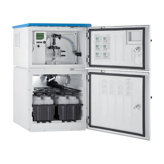
Liquistation CSF48
Automatic sampler for liquid media
These Instructions are Brief Operating Instructions; they are
not a substitute for the Operating Instructions pertaining to
the device.
Detailed information on the device can be found in the
Operating Instructions and in the other documentation
available at:
• www.endress.com/device-viewer
• Smart phone/tablet: Endress+Hauser Operations App
Solutions
Services
Advertisement
Table of Contents

Related Manuals for Endress+Hauser Liquistation CSF48


Summary of Contents for Endress+Hauser Liquistation CSF48
- Page 1 These Instructions are Brief Operating Instructions; they are not a substitute for the Operating Instructions pertaining to the device. Detailed information on the device can be found in the Operating Instructions and in the other documentation available at: • www.endress.com/device-viewer • Smart phone/tablet: Endress+Hauser Operations App...
- Page 2 Liquistation CSF48 Order code 00X00-XXXX0XX0XXX Ser. No.: X000X000000 TAG No.: XXX000 Serial number www.endress.com/deviceviewer Endress+Hauser Operations App A0023555 Endress+Hauser...
-
Page 3: Table Of Contents
Liquistation CSF48 Table of contents Table of contents Document information ............4 Warnings . -
Page 4: Document Information
Document information Liquistation CSF48 Document information Warnings Structure of information Meaning This symbol alerts you to a dangerous situation. DANGER Failure to avoid the dangerous situation will result in a fatal or serious injury. Causes (/consequences) Consequences of non-compliance (if applicable) ‣... -
Page 5: Documentation
Document information Documentation The following manuals which are available on the product pages on the internet complement these Operating Instructions: • Operating Instructions for Liquistation CSF48, BA00443C – Device description – Commissioning – Operation – Software description (excluding sensor menus; these are described in a separate manual - see below) –... -
Page 6: Basic Safety Instructions
Designated use Liquistation CSF48 is a stationary sampler for liquid media. The samples are taken discontinuously using a vacuum pump or peristaltic pump or sampling assembly and are then distributed into sampling containers and refrigerated. -
Page 7: Operational Safety
Liquistation CSF48 Basic safety instructions Operational safety Before commissioning the entire measuring point, verify that all connections are correct. Ensure that electrical cables and hose connections are undamaged. Do not operate damaged products, and safeguard them to ensure that they are not operated inadvertently. -
Page 8: Incoming Acceptance And Product Identification
Incoming acceptance and product identification Liquistation CSF48 Incoming acceptance and product identification Incoming acceptance Verify that the packaging is undamaged. Notify your supplier of any damage to the packaging. Keep the damaged packaging until the matter has been settled. -
Page 9: Scope Of Delivery
Liquistation CSF48 Incoming acceptance and product identification Scope of delivery The scope of delivery comprises: • 1 Liquistation CSF48 with: – The ordered bottle configuration – Optional hardware • Accessories kit – For peristaltic or vacuum pump: Connection nipple for suction line with various angles (straight, 90°), Allen key (for version with vacuum pump only) –... -
Page 10: Installation
471 (18.5) 753 (29.7) 355 (14.0) 125 (4.9) 816 (32.1) 625 (24.6) 471 (18.5) 753 (29.7) 355 (14.0) 125 (4.9) 816 (32.1) A0025857 1 Dimensions of Liquistation CSF48 plastic version, without/with stand, dimensions in mm (in) Suction line connection Endress+Hauser... - Page 11 743 (29.3) 355 (14.0) 125 (4.9) 816 (32.1) 624 (24.6) 467 (18.4) 743 (29.3) 355 (14.0) 125 (4.9) 816 (32.1) A0024423 2 Dimensions of Liquistation CSF48 CSF34 stainless steel version, without/with stand, dimensions in mm (in) Suction line connection Endress+Hauser...
- Page 12 Installation Liquistation CSF48 4.1.2 Installation site For version with pump A0024411 3 Installation conditions for the Liquistation Correct The suction line must be routed with a downward slope to the sampling point. Incorrect The sampler should never be mounted in a place where it is exposed to aggressive gases.
- Page 13 A0024412 4 Installation conditions for Liquistation CSF48 with Samplefit CSA420 sampling assembly Note the following when installing the sampling assembly in a pipe: • The best installation location is in the ascending pipe (pos. 2). Installation is also possible in the horizontal pipe (pos.
- Page 14 Installation Liquistation CSF48 • Protect the device against strong magnetic fields. • Make sure air can circulate freely at the side panels of the cabinet. Do not mount the device directly against a wall. Allow at least 150 mm (5.9") from the wall to the left and right.
- Page 15 Liquistation CSF48 Installation 4.1.4 Connection for suctioning samples • Maximum suction height: – Vacuum pump: Standard 6 m (20 ft) Optional 8 m (26 ft) – Peristaltic pump: standard 8 m (26 ft) • Maximum hose length: 30 m (98 ft) •...
- Page 16 Installation Liquistation CSF48 Note the following when erecting the device: • Always route the suction line so that it slopes upwards from the sampling point to the sampler. • The sampler must be located above the sampling point. • Avoid siphoning effects in the suction line.
-
Page 17: Installation
Liquistation CSF48 Installation Installation 4.2.1 Connecting the suction line at the side on version with pump When installing the device, take the installation conditions into account. Route the suction line from the sampling point to the device. Screw the suction line onto the device' s hose connection. - Page 18 Installation Liquistation CSF48 Connecting the suction line on version with vacuum pump A0013708 A0013707 8 Suction line connected from below 7 Connecting the suction line from the side (as- delivered state) Hose Fixing clip for hose gland Thread adapter nut Hose gland Unscrew the thread adapter nut (item 3).
- Page 19 Liquistation CSF48 Installation Connecting the suction line on version with peristaltic pump A0013705 A0013706 9 Connecting the suction line from the side (as- 10 Suction line delivered state) Small thread adapter nut Hose Thread adapter nut Hose gland Unscrew the thread adapter nut (item 3) and the hose fitting (item 4) from the side panel.
- Page 20 Connect the black compressed air lines from the sampler (item 6) to the connections on the sampling assembly. In the case of the Liquistation CSF48 version without an internal compressor, connect the black compressed air hose (item 5) to the external compressed air supply.
-
Page 21: Sampling With A Flow Assembly
The ball valve and the valve are not included in the scope of supply. If necessary, please request a quote from your Endress+Hauser sales center. The reference number is CTSP- SB15P1 (TSP 71180379) A0023437 ... -
Page 22: Post-Installation Check
Installation Liquistation CSF48 Post-installation check Verify that the suction line is securely connected to the device. Visually check that the suction line is installed correctly from the sampling point to the device. Verify that the rotating arm is correctly engaged. -
Page 23: Electrical Connection
Liquistation CSF48 Electrical connection Electrical connection Connecting the sampler WARNING Device is live Incorrect connection may result in injury or death ‣ The electrical connection may be performed only by an electrical technician. ‣ The electrical technician must have read and understood these Operating Instructions and must follow the instructions contained therein. - Page 24 Electrical connection Liquistation CSF48 5.1.2 Cable types • Power supply: e.g. NYY-J; 3-wire; min. 2.5 mm • Analog, signal and transmission cables: e.g. LiYY 10 x 0.34 mm The terminal connection is located under an additional protective cover in the upper rear section of the device.
- Page 25 Liquistation CSF48 Electrical connection 5.1.3 Removing the rear panel of the dosing compartment Open the door of the dosing compartment. Using an 5mm Allen key, release the rear panel by turning the lock clockwise. CLOSE OPEN A0012803 Lift up the rear upper panel and pull it off towards the back.
- Page 26 Electrical connection Liquistation CSF48 5.1.4 Removing the rear panel of the sampling compartment A0012825 ‣ Remove the bolt on the rear of the dosing compartment. A0012824 ‣ Remove the bolt on the rear panel. 5.1.5 Removing the cover on the power unit...
- Page 27 Liquistation CSF48 Electrical connection A0012831 Release the screw with an Allen key (5 mm). Remove the cover of the power unit from the front. When reassembling make sure that the seals are seated correctly. 5.1.6 Power supply terminal assignment The power supply is connected via plug-in terminals.
- Page 28 Electrical connection Liquistation CSF48 A0013237 15 Terminal assignment Assignment: 100 to 120 V/200 to 240 V AC ±10 % Assignment: 24 V DC +15/-9 % Rechargeable batteries (optional) Internal 24 V voltage Fuses (only for batteries) Endress+Hauser...
- Page 29 Liquistation CSF48 Electrical connection 5.1.7 Cable terminals Plug-in terminals for Memosens and PROFIBUS/RS485 connections Insert the cable until the limit stop Press the screwdriver against the clip Remove the screwdriver (closes the (opens the terminal) terminal) After connection, make sure that every cable end is securely in place. Terminated cable ends, in particular, tend to come loose easily if they have not been correctly inserted as far as the limit stop.
-
Page 30: Connecting Modules And Sensors
Electrical connection Liquistation CSF48 Connecting modules and sensors 5.2.1 Connection compartment in the controller housing A0013238 A0012843 1 L base module Sampler controller The controller housing has a separate connection Display cover open, version with L base module compartment. Release the six cover screws to open the connection compartment: ‣... - Page 31 Liquistation CSF48 Electrical connection 5.2.2 SYS base module Int. Com 24V DC Display Service Power A0013172 16 SYS base module SD card slot Connecting cable to sampler controller Slot for the display cable Voltage connection Service interface Internal device connection. Do not disconnect the plug!
- Page 32 Electrical connection Liquistation CSF48 5.2.3 E base module 24 VDC Power A0016535 17 E basic module Indicator LEDs Slot for display cable Voltage connection Service interface Alarm relay connection Connections for 2 Memosens sensors (optional) Power supply for digital fixed cable sensors...
- Page 33 Liquistation CSF48 Electrical connection 85 86 24VDC Alarm Sensor supply Power – (internal) – – 0/4 ... 20 mA Display Service HART – Sensor A0016537 18 E basic module wiring diagram 5.2.4 Connecting the sensors Sensor types with Memosens protocol...
- Page 34 Electrical connection Liquistation CSF48 Sensor Sensor A0023038 A0023039 19 sensors without additional supply voltage 20 sensors with additional supply voltage Sensor Sensor 1 Sensor 2 Sensor A0016197 21 sensors with and without additional supply voltage on 2DS sensor module...
- Page 35 Liquistation CSF48 Electrical connection Sensor connection ‣ Guide the sensor cable via the rear panel to the controller housing towards the front. → 25 and → 26 A0016360 22 Gland to the controller Only use terminated genuine cables where possible.
- Page 36 Electrical connection Liquistation CSF48 Connecting the ferrules of the sensor cable to the E base module ‣ Ground the outer shield of the cable via the metal gland to the left of the E base module. 32 31 A0016356 ...
- Page 37 Liquistation CSF48 Electrical connection Analog inputs and binary inputs/outputs 125 123 124 225 223 224 191 192 291292 145 146 245 246 A0012988 25 Position of the terminals Analog inputs 1 and 2 Binary inputs/outputs Analog inputs A0012989 26...
- Page 38 Electrical connection Liquistation CSF48 CSXxx CMxx A0028652 27 With two-wire transmitter, e.g. Liquiline M CM42 CSXxx FMU90 A0028653 28 With four-wire transmitter, e.g. Prosonic S FMU90 Binary inputs A0013381 29 Assignment of binary inputs 1 and 2...
- Page 39 Liquistation CSF48 Electrical connection When connecting to an internal voltage source, use the terminal connection on the rear of the dosing compartment. The connection is located on the lower terminal strip (on the far left, + and -), (→ 27)
- Page 40 Electrical connection Liquistation CSF48 Binary outputs with relay option A0016343 33 Relay Binary output 1 Binary output 2 The left relay is activated with binary output 1, while the right relay is activated by binary output 2. A0016348 34...
-
Page 41: Terminal Assignment For Input/Output Signals
Liquistation CSF48 Electrical connection Terminal assignment for input/output signals Input signals • 2 analog signals 0/4 to 20 mA • 2 binary signals > 100 ms pulse width or edge Signals of digital sensors with Memosens protocol (optional) Output signals 2 binary signals >... -
Page 42: Connecting Additional Inputs, Outputs Or Relays
Electrical connection Liquistation CSF48 Connecting additional inputs, outputs or relays WARNING Module not covered No shock protection. Danger of electric shock! ‣ If you are modifying or extending your hardware, always fill the slots from top to bottom. Do not leave any gaps. - Page 43 Liquistation CSF48 Electrical connection 5.4.2 Current outputs – – – – – – 37 Module 38 Wiring 39 Module 40 Wiring diagram diagram A maximum of 6 current outputs are supported. Endress+Hauser...
- Page 44 Electrical connection Liquistation CSF48 5.4.3 Relay Module 2R Module 4R 44 Wiring 41 Module 42 Wiring 43 Module diagram diagram A maximum of 4 relay outputs are supported. Endress+Hauser...
-
Page 45: Connecting Digital Communication
Liquistation CSF48 Electrical connection Connecting digital communication 5.5.1 Module 485 128/SW Service DGND 46 Wiring 45 Module diagram LEDs on front of module Description Color Description RJ45 LNK/ACT • Off = Connection is not active • On = Connection is active •... - Page 46 Electrical connection Liquistation CSF48 DIP switches on front of module Factory setting Assignment 1-128 Bus address (→ "Commissioning/communication") Write protection: "ON" = configuration not possible via the bus, only via local operation Service If the switch is set to "ON" , the user settings for Ethernet addressing are saved and connection settings programmed into the device at the factory are activated: IP address=192.168.1.212, Subnet mask=255.255.255.0, Gateway=0.0.0.0, DHCP=Off.
- Page 47 Liquistation CSF48 Electrical connection DIP switches on front of module Factory setting Assignment 1-128 Bus address (→ "Commissioning/communication") Write protection: "ON" = configuration not possible via the bus, only via local operation Service If the switch is set to "ON" , the user settings for Ethernet addressing are saved and connection settings programmed into the device at the factory are activated: IP address=192.168.1.212, Subnet mask=255.255.255.0, Gateway=0.0.0.0, DHCP=Off.
-
Page 48: Hardware Settings
Electrical connection Liquistation CSF48 5.5.3 Bus termination There are two ways to terminate the bus: 1. Internal terminating resistor (via DIP switch on the module board) "OFF" "ON" 49 DIP switches for internal terminating resistor ‣ Using a suitable tool, such as a tweezers, set all 4 DIP switches to the "ON" position. -
Page 49: Ensuring The Degree Of Protection
Liquistation CSF48 Electrical connection Set the desired bus address via the DIP switches of module 485. For PROFIBUS DP, valid bus addresses are anything between 1 and 126, and anything between 1 and 247 for Modbus. If you configure an invalid address, software addressing is automatically enabled via the local configuration or via the fieldbus. -
Page 50: Post-Connection Check
Electrical connection Liquistation CSF48 Post-connection check WARNING Connection errors The safety of people and of the measuring point is under threat. The manufacturer does not accept any responsibility for errors that result from failure to comply with the instructions in this manual. -
Page 51: Operation Options
Liquistation CSF48 Operation options Operation options Overview 6.1.1 Display and operating elements Display (with red display background in alarm condition) Navigator (jog/shuttle and press/hold EH_CSF 09:11:05 31.03.2015 function) Soft keys (function depends on menu) MODE A0025501 54 Overview of operation 6.1.2... -
Page 52: Access To The Operating Menu Via The Local Display
Operation options Liquistation CSF48 Access to the operating menu via the local display 6.2.1 Operating concept MODE MODE Turning the navigator: moving the cursor in the menu Pressing the soft key: selecting the menu directly Menu/Language MODE Turning the navigator: selecting a value (e.g. from a list) -
Page 53: Configuration Options
Liquistation CSF48 Operation options 6.2.2 Locking or unlocking operating keys Locking operating keys ‣ Press the navigator for longer than 2 s. A context menu for locking the operating keys is displayed. You have the choice of locking the keys with or without password protection. "With password"... - Page 54 Operation options Liquistation CSF48 6.3.3 Numerical values • You are changing a variable. • The maximum and minimum values for this variable are shown on the display. • Set a value within this range. • Example: Menu/Operation/Display/Contrast Menu/...ration/Display/Contrast 6.3.4 Actions •...
- Page 55 Liquistation CSF48 Operation options 6.3.5 Free text • You are assigning an individual designation. • Enter a text. You can use the characters in the editor for this purpose (upper-case and lower-case letters, numbers and special characters). • Using the soft keys, you can: –...
- Page 56 Operation options Liquistation CSF48 6.3.6 Tables • Tables are needed to map mathematical functions or to enter irregular interval samples. • You edit a table by navigating through rows and columns with the navigator and changing the values of the cells.
-
Page 57: Commissioning
Liquistation CSF48 Commissioning Commissioning Function check WARNING Incorrect connection, incorrect supply voltage Safety risks for staff and device malfunctions ‣ Check that all connections have been established correctly in accordance with the wiring diagram. ‣ Ensure that the supply voltage matches the voltage indicated on the nameplate. -
Page 58: Basic Setup
Commissioning Liquistation CSF48 Basic setup Making basic settings Device tag: Give your device any name of your choice (max. 32 characters). Set date: Correct the set date if necessary. Set time: Correct the set time if necessary. Number of bottles: Correct the set number of bottles if necessary. -
Page 59: Sampling Programs
Liquistation CSF48 Commissioning Sampling programs 7.4.1 Difference between program types The following box provides an overview of the differences between the Basic, Standard and Advanced program types. Basic (1 sampling program) Start condition: • Immediate activation Stop condition: • Immediate •... - Page 60 Commissioning Liquistation CSF48 7.4.2 Manual sampling Manual sampling is triggered by the MAN soft key. This pauses any program currently running. The current bottle configuration and the current sample volume are displayed. You can select the distributor position. In peristaltic systems, you can also change the sample volume.
- Page 61 Liquistation CSF48 Commissioning Select the Bottle change mode after number of samples or time for average samples. With the option "Bottle change after a time", you can enter the change time and bottle synchronization (None, 1st bottle change time, 1st time of change + bottle number). The description for this can be found in the "Bottle synchronization"...
- Page 64 *71314894* 71314894 www.addresses.endress.com...