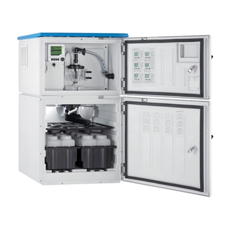
Endress+Hauser Liquistation CSF48 Brief Operating Instructions
Automatic sampler for liquid media
Hide thumbs
Also See for Liquistation CSF48:
- Operating instructions manual (268 pages) ,
- Operation and setting (188 pages) ,
- Brief operating instructions (76 pages)

Related Manuals for Endress+Hauser Liquistation CSF48


Summary of Contents for Endress+Hauser Liquistation CSF48
- Page 1 Operating Instructions/Brief Operating Instructions Liquistation CSF48 Automatic sampler for liquid media Commissioning BA443C/07/EN/13.10 71122369 Valid as of: Software version 01.01.00...
- Page 2 Overview of documentation Operating Instructions The Operating Instructions are split into several parts: Commissioning (BA443C) • All steps that have to be carried out once only during the initial commissioning • Description of menus: – Basic settings – Display/Operation • Technical data Operation &...
-
Page 3: Table Of Contents
Liquistation CSF48 Table of contents Safety instructions ..4 Binary input, passive ....46 Analog input, passive/active ... 46 Designated use . -
Page 4: Safety Instructions
Liquistation CSF48 Safety instructions Designated use The Liquistation CSF48 is a stationary sampler for liquid media. The samples are taken discontinuously using a vacuum or peristaltic pump, distributed to sampling containers and cooled. The sampler is designed for use in the following applications: •... -
Page 5: Return
The electromagnetic compatibility indicated only applies to a device that has been connected in accordance with the instructions in these Operating Instructions. Return The Liquistation CSF48 is repaired on site. Contact your Endress+Hauser Service. Notes on safety conventions and icons 1.5.1 Warnings... -
Page 6: Identification
Identification Liquistation CSF48 Identification Device designation 2.1.1 Nameplate Nameplates can be found: • On the inside of the upper door • On the packaging (adhesive label, portrait format) The nameplate provides you with the following information on your device: • Order code •... -
Page 7: Certificates And Approvals
The manufacturer confirms successful testing of the product by affixing to it the 4 mark. Device description A complete sampling unit comprises: • Liquistation CSF48, with the following depending on the version ordered: – Controller with display, soft keys and navigator – Vacuum or peristaltic pump for sampling –... -
Page 8: Installation
Distributionplate (depending on the sample bottles selected) Distribution arm a0013207 Fig. 2: Example of a Liquistation CSF48, version with peristaltic pump Peristaltic pump Warning! Danger of injury due to rotating parts Do not open the cover of the peristaltic pump while the pump is operating. -
Page 9: Installation Conditions
Liquistation CSF48 Installation Installation conditions 4.2.1 Dimensions a0013080 Fig. 3: Dimensions of plastic version of Liquistation CSF48 without and with stand Suction line connection Endress+Hauser... - Page 10 Installation Liquistation CSF48 a0013082 Fig. 4: Dimensions of stainless steel version of Liquistation CSF48 without and with stand Suction line connection Endress+Hauser...
- Page 11 Liquistation CSF48 Installation 4.2.2 Mounting location a0011693 Fig. 5: Mounting conditions Correct The suction line must be routed with a downward slope to the sampling point. Incorrect The sampler should never be mounted in a place where it is exposed to aggressive gases.
- Page 12 Liquistation CSF48 4.2.3 Mechanical connection Foundation plan a0012761 Fig. 6: Foundation plan Fasteners (4 x M10) Cable inlet Outlet for condensate and overflow > DN 50 Sample supply from below > DN 80 – – – Dimensions of Liquistation CSF48 Endress+Hauser...
-
Page 13: Erecting The Sampler
Liquistation CSF48 Installation 4.2.4 Connection for sampling • Maximum suction height: Vacuum pump: standard 6 m (20 ft), optional 8 m (26 ft) Peristaltic pump: standard 8 m (26 ft) • Maximum hose length: 30 m (98 ft) • Hose connection diameter: Vacuum pump: internal diameter of 10 mm (3/8"), 13 mm (1/2"), 16 mm (5/8") or... - Page 14 Installation Liquistation CSF48 4.3.2 Connecting the suction line from below If the suction line is connected from below, the suction line is routed upwards behind the rear panel of the sample compartment. First remove the rear panel of the dosing chamber and sample compartment as described in the "Wiring"...
- Page 15 Liquistation CSF48 Installation a0013708 a0013707 Abb. 9: Suction line connected from below Abb. 8: Vacuum pump with suction line connected at the side Hose Fixing clip for hose gland Thread adapter nut Hose gland Connecting the suction line in the version with the peristaltic pump Unscrew the thread adapter nut (item 3) and the hose gland (item 4) from the side panel.
-
Page 16: Sampling With A Flow Assembly
Installation Liquistation CSF48 Sampling with a flow assembly The sample is taken directly from the flow assembly which is installed in the sampler stand. The flow assembly is used when sampling in pressurized systems, e.g.: • Containers located at a higher level •... -
Page 17: Post-Installation Check
Liquistation CSF48 Installation a0013458 Fig. 13: Example: Sampling from pressure piping Ball valve 1 Valve 2 Use the ball valve 1 to set the flow rate to 1000 l/h ... 1500 l/h. When the sampling cycle begins, you can use one of the relay outputs to control and open valve 2. The medium flows through the pipe and the flow assembly into the outflow. -
Page 18: Wiring
Wiring Liquistation CSF48 Wiring Warning! • The electrical connection may only be established by an electrical technician. • The electrical technician must have read and understood these Operating Instructions and must follow the instructions they contain. • Prior to beginning any wiring work, make sure voltage is not applied to any of the cables. - Page 19 Liquistation CSF48 Wiring 5.1.3 Removing the rear panel of the dosing compartment Open the dosing compartment door to remove the rear panel of the dosing compartment. CLOSE OPEN a0012803 a0012826 Fig. 14: Screw above the dosing compartment Fig. 15: Lift up the top rear panel and pull it back to...
- Page 20 Wiring Liquistation CSF48 5.1.5 Removing the cover on the power unit Warning! Make sure the device is disconnected from the power source before you remove the cover of the power unit. a0012831 Fig. 18: Removing the cover on the power unit...
- Page 21 Liquistation CSF48 Wiring 5.1.6 Power supply terminal assignment The power supply is connected via plug-in terminals. Connect the ground to one of the ground connections. Rechargeable batteries are available as an option (for battery type see section Technical Data). Fuses are available as an option (see section Technical Data).
-
Page 22: Terminal Assignment For Input/Output Signals
Wiring Liquistation CSF48 5.1.7 Cable terminals 1. Insert a suitable screwdriver into the opening of the terminal clip (square opening) as far as the screwdriver can go. a0003602 Fig. 20: Opening the terminal 2. Insert the terminated end of the cable into the terminal opening (round opening). -
Page 23: Optional Sensor Inputs, Current Outputs And Relays
Liquistation CSF48 Wiring Optional sensor inputs, current outputs and relays 5.3.1 Connection compartment in the controller housing The controller housing has a separate connection compartment. Release 6 housing screws to open the display cover: a0012843 Fig. 23: Release 6 housing screws with a... - Page 24 Wiring Liquistation CSF48 5.3.2 SYS basic module a0013172 Fig. 25: SYS basic module SD card slot Connection cable to sampler controller Slot for the display cable Power connection Service interface Internal device connection. Do not disconnect the connector! 5.3.3 L basic module a0012841 Fig.
- Page 25 Liquistation CSF48 Wiring a0012842 Fig. 27: L basic module wiring diagram 5.3.4 Plug-in terminals for Memosens connections a0012691 a0012692 a0012693 Fig. 28: Press the screwdriver against Fig. 29: Insert the cable until the limit Fig. 30: Remove the screwdriver the clip (opens the terminal)
- Page 26 Wiring Liquistation CSF48 5.3.5 All other plug-in terminals a0012694 a0012695 a0012696 Fig. 31: Insert the screwdriver (opens Fig. 32: Insert the cable Fig. 33: Remove the screwdriver the terminal) (closes the terminal) 5.3.6 Sensor types with Memosens protocol Sensor types...
- Page 27 Liquistation CSF48 Wiring Connecting the end sleeves of the sensor cable to the L basic module Note! The outer shield of the cable is grounded by means of the metal gland on the left of the L basic module. a0013451 Fig.
-
Page 28: Sampler Controller
Wiring Liquistation CSF48 Sampler controller 5.4.1 Analog inputs and binary inputs/outputs 125 123 124 225 223 224 191 192 291292 145 146 245 246 a0012988 Fig. 37: Position of the terminals Analog inputs 1 and 2 Binary inputs/outputs 5.4.2 Analog inputs a0012989 Fig. - Page 29 Liquistation CSF48 Wiring 5.4.3 Binary inputs a0013381 Fig. 39: Assignment of binary inputs 1 and 2 Binary input 1 (191/192) Binary input 2 (291/292) a0013404 Fig. 40: Connection example binary input with external voltage source When connecting to an internal voltage source use the terminal connection on the rear of the dosing chamber.
-
Page 30: Post-Connection Check
Wiring Liquistation CSF48 a0013407 Fig. 42: Connection example binary output with external voltage source When connecting to an internal voltage source use the terminal connection on the rear of the dosing chamber. Connect the cable cores to terminals "+" and "-" (bottom terminal block, left), see section Power supply terminal assignment. -
Page 31: Operation
Liquistation CSF48 Operation Operation Display and operating elements 6.1.1 Overview Navigator (jog/shuttle and press/hold function) Soft keys (function depends on the menu) Display (red background in the event of an a0013350 Fig. 43: Overview of operation error) 6.1.2 Display Menu path and/or device designation Status display Assignment of the soft keys, e.g. -
Page 32: Operation Concept
Operation Liquistation CSF48 Operation concept a0013353-en a0013354-en Fig. 45: Pressing the soft key: selecting the menu directly Fig. 46: Turning the navigator: moving the cursor in the menu a0013355-en a0013356-en Fig. 47: Pressing the navigator: launching a function Fig. 48: Turning the navigator: selecting a value (e.g. from... -
Page 33: Configuration Options
Liquistation CSF48 Operation Configuration options 6.3.1 Display only • You can only read the values but cannot change them. • Typical read-only values are: sensor data and system information • Example: Menu/Setup/Inputs/../Sensor type 6.3.2 Picklists • You receive a list of options. -
Page 34: Commissioning
Commissioning Liquistation CSF48 6.3.5 Customized text • You are assigning an individual designation. • Enter a text. You can use the characters in the editor for this purpose (upper-case and lower-case letters, numbers and special characters). • Example: Menu/Setup/General settings/Device tag... -
Page 35: General Settings
Liquistation CSF48 Commissioning 7.2.2 Display settings Path: Menu / Display/Operation Function Options Info Contrast 5 to 95 % Adjust the screen settings to suit your working environment. Backlight Options Backlight="Automatic" • On The backlighting is switched off automatically after • Off a short time if a button is not pressed. - Page 36 Commissioning Liquistation CSF48 7.3.1 General settings Path: Menu/Setup/General settings Function Options Info Device tag Customized text, 20 Select any name for your controller. Use the TAG characters name for example. Temperature unit Options • °C • °F • K Factory setting °C...
- Page 37 Liquistation CSF48 Commissioning Path: Menu/Setup/General settings/Date/Time Function Options Info Options The controller adapts the summertime/normal • Off time changeover automatically if you choose • Europe European or American daylight saving time. • USA Manual means that you can specify the start and •...
- Page 38 Commissioning Liquistation CSF48 Path: Menu/Setup/General settings/Logbooks Function Options Info Calibration logbook Options Decide whether you want to receive a diagnostic • Off message from the controller in the event of memory Diagnostic logbook • On overrun of the logbook in question.
- Page 39 Liquistation CSF48 Commissioning Path: Menu/Setup/General settings/Logbooks Function Options Info Data logbook Options Ring buffer • Off If the memory is full, the latest entry automatically • Ring buffer overwrites the oldest entry. • Fill up buffer Fill up buffer If the memory is full, there is an overflow, i.e. no Factory setting new values can be saved.
- Page 40 Commissioning Liquistation CSF48 7.3.4 Automatic hold (optional) Path: Menu/Setup/General settings/Automatic hold Function Options Info Device specific hold Setup menu Options Decide whether a hold should be output at the • Disabled current output when the particular menu is Diagnostics menu •...
- Page 41 Liquistation CSF48 Commissioning Function Options Info Diag. output Options You can use this function to select a relay output • None and/or binary output to which the diagnostic • Alarm relay message should be assigned. • Relay 1 to n (depends on...
- Page 42 Commissioning Liquistation CSF48 Path: ET_SwtestMenu/ET_Setup/ET_GeneralSettings Function Options Info Power failure Options • Resume program • Stop program Factory setting Stop program Dosing chamber Options Dosing with pressure e.g. in conditions with low • Dose without pressure suction heights and slight counterpressure or low •...
- Page 43 Liquistation CSF48 Commissioning Path: ET_SwtestMenu/ET_Setup/ET_GeneralSettings Function Options Info Diagnostics settings Sensor fouling Warning 0 ... 10 Indicates maintenance work must be performed on the conductivity sensors. Factory setting Alarm 0 ... 10 Factory setting Pump tube life Control Options Indicates the pump hose has to be exchanged.
- Page 44 Commissioning Liquistation CSF48 Path: ET_SwtestMenu/ET_Setup/ET_GeneralSettings Function Options Info Cooling control Options The temperature regulator is switched off for a cer- • Standard operation tain time if quick cool-down is selected. • Quick cool down Factory setting Standard operation Defrosting The automatic defrosting function is preset at the factory. The following changes may only be made by experts.
- Page 45 Liquistation CSF48 Commissioning • Example: 7.3.8 Programming for automatic sampling Create a sampling program in the general overview under "Select sampling program/New/ Basic" or in the menu "Menu/Setup/Sampling programs/Setup program/New/Basic": Enter the "Program name". The bottle configuration from the setup is displayed.
-
Page 46: Technical Data
Technical data Liquistation CSF48 Technical data Input 8.1.1 Input types • 2 analog inputs • 2 binary inputs • 1 or 2 digital sensors with Memosens protocol (optional) 8.1.2 Measured variables See documentation of the connected sensor. Temperature inputs 8.2.1 Measuring range Temperature: -30 to 70 °C (-20 to 160 °F) -
Page 47: Output
Liquistation CSF48 Technical data Output 8.5.1 Output signal 2 binary outputs (standard): Open collector, max. 30 V, 200 mA Depending on the version: • 2 x 0/4 to 20 mA, active, galvanically isolated from the sensor circuits and from one another 8.5.2 Communication... -
Page 48: Relay Outputs
Technical data Liquistation CSF48 Cable cross-section Max. 2.5 mm² (14 AWG) Relay outputs 8.7.1 Electrical specification Relay types • 2 x changeover contact connected to binary output (optional) • 1 single-pin changeover contact (alarm relay) Relay switching capacity • Power unit (alarm relay) –... -
Page 49: Performance Characteristics
Liquistation CSF48 Technical data 8.8.3 Cable entry Depending on the version: • 1 x M25, 7 x M20 cable gland • 1 x M25, 1 x M20 cable gland Permitted cable diameter • M20x1.5mm: 7 to 13 mm (0.28 to 0.51") •... - Page 50 Technical data Liquistation CSF48 8.9.2 Dosing volume • Vacuum pump: 20 to 350 ml (0.7 to 12 fl.oz.) • Peristaltic pump: 10 to 9999 ml (0.7 to 340 fl.oz.) 8.9.3 Dosing accuracy • Vacuum pump: ±5 ml (0.17 fl.oz.) or 5 % of the set volume •...
-
Page 51: 8.10 Environment
Liquistation CSF48 Technical data 8.10 Environment 8.10.1 Ambient temperature range • With temperature control unit: -20 to 40 °C (0 to 100 °F) • Without temperature control unit: 0 to 40 °C (32 to 100 °F) 8.10.2 Storage temperature –20 to 60 °C (0 to 140 °F) 8.10.3 Electromagnetic compatibility... -
Page 52: 8.12 Mechanical Construction
Technical data Liquistation CSF48 8.12 Mechanical construction 8.12.1 Dimensions --> "Mounting" section 8.12.2 Weight CSF48 sampler version Weight Plastic version without refrigeration 91 kg (201 lbs) Plastic version with refrigeration 101 kg (223 lbs) Plastic version without refrigeration and with... - Page 53 Liquistation CSF48 Technical data Wetted parts Vacuum pump Peristaltic pump Dosing system outflow tubing Silicone Pump tubing Silicone Distribution arm Plastic PP Distribution arm cover Plastic PE Distribution plate Plastic PS Composite container/bottles Plastic PE, glass (depending on version) Suction line...
-
Page 54: Index
Liquistation CSF48 Index Identification ......6 Nameplate......6 Approvals . - Page 55 Liquistation CSF48 Sampling Manual ......44 Scope of delivery ......6 Sensors Connection .
- Page 56 BA443C/07/EN/13.10 FM+SGML 6.0 71122369...