Endress+Hauser OXY5500 Operating Instruction
Optical oxygen analyzer
Hide thumbs
Also See for OXY5500:
- Operating instructions manual (86 pages) ,
- Overview manual (56 pages) ,
- Safety manual (28 pages)
Table of Contents
Troubleshooting

Related Manuals for Endress+Hauser OXY5500


Summary of Contents for Endress+Hauser OXY5500
- Page 1 BA02195C/66/EN/01.21 Products Solutions Services Valid as of version SSI v1.4.1.0521 (Device firmware) Operating Instruction OXY5500 Optical Oxygen Analyzer ATEX/IECEx/UKEX: Zone 2 cCSAus: Class I, Division 2/Zone 2...
- Page 2 Copyright © 2021 Endress+Hauser, Inc. No part of this manual may be reproduced in whole or in part without the express written permission of Endress+Hauser, Inc. Endress+Hauser reserves the right to change product design and specifications at any time without prior notice.
-
Page 3: Table Of Contents
About the OXY5500 Analyzer ........ - Page 4 Equipment and materials ........4-36 Calibration gas connections to the OXY5500 analyzer ....4-38 Connecting the gas inlet for analyzers without the sample conditioning system (SCS) .
- Page 5 BA02195C OXY5500 Optical Oxygen Analyzer Digitals Menu Options ......... 4-50 RS-232 settings .
- Page 6 OXY5500 Optical Oxygen Analyzer BA02195C Required tools and hardware ........B-4 Removing the electro-optical module .
-
Page 7: Associated Documents
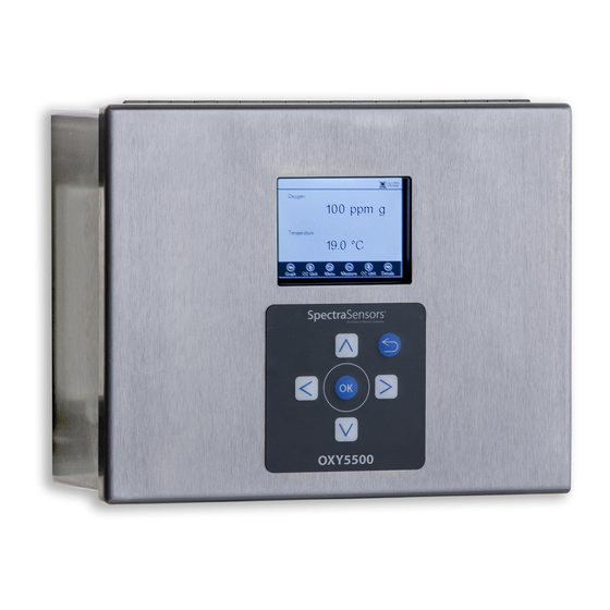
1 - I NTRODUCTION Endress+Hauser’s OXY5500 Optical Oxygen Analyzer is a stand-alone device designed to detect oxygen in gases such as natural gas and air. Its design is based on fluorescence quenching technology that creates very stable, internally referenced measured values. -
Page 8: Who Should Read This Manual
Take a moment to familiarize yourself with the content included in this Operating Instruction by reviewing the "Table of Contents". There are a number of options and accessories available for the OXY5500 analyzers. This manual has been written to address the most common options and accessories. - Page 9 BA02195C OXY5500 Optical Oxygen Analyzer WARNING - USE DAMP CLOTH TO CLEAN DISPLAY AND KEYPAD TO AVOID STATIC ELECTRICITY DISCHARGE. Use appropriate tools to avoid ______________________________________________________ electrostatic discharge. AVERTISSEMENT - AUX CHARGES ELECTROSTATIQUES. UTILISER UN CHIFFON HUMIDE POUR NETTOYER L’AFFICHEUR ET LE CLAVIER.
-
Page 10: Instructional Symbols
Maximum voltage and current specifications for fuses. Documents Provided with the OXY5500 Analyzer Each OXY5500 analyzer shipped from the factory is packaged with documents and software that are to be used for system operation, as applicable to the system configuration. Typically, each shipment includes the following documents: •... -
Page 11: About The Oxy5500 Analyzer
The rugged design and low power consumption makes the OXY5500 ready for an indoor or outdoor application in Class I, Division 2, Groups A, B, C and D, T4. In addition, the analyzer is also marked II 3 G Ex nA IIC T3 Gc IP64. -
Page 12: Oxygen Probe
OXY5500 Optical Oxygen Analyzer BA02195C GRAPHIC DISPLAY KEYPAD OXYGEN PROBE SIGNAL WIRING PORT ANALYZER POWER PORT CHASSIS GROUND STUD PRESSURE SENSOR (OPTIONAL) RTD PROBE (pt100) Figure 1–1 OXY5500 analyzer to the oxygen sensor. Depending on the application and/or ambient conditions, the SCS may also contain a heater and thermostat to maintain the interior of an optional enclosure at a constant temperature. - Page 13 OXY5500 Optical Oxygen Analyzer AC/DC POWER CONNECTION ELECTRO-OPTICAL MODULE RJ-45 AND USB CONNECTORS RELAYS PROTECTIVE EARTH GROUND FUSE ENCLOSURE OPTICAL MODULE WITH SMA CONNECTOR Figure 1–2 Inside cabinet view (AC version) OP-3 OP-6 OP-9 Figure 1–3 OXY5500 probe sensor spot – Endress+Hauser...
-
Page 14: How An Oxygen Sensor Works
OXY5500 Optical Oxygen Analyzer BA02195C Endress+Hauser’s fiber-optic oxygen sensors are made with 2 mm polymer optical fibers. The sensing portion is a 4 mm stainless steel probe. As a standard, the probe is mounted in a 1/4 in. Swagelok Union Tee using a 1/4 in. -
Page 15: Safety Guidelines
Figure 1–6 Principle of dynamic quenching of luminescence by molecular oxygen Safety Guidelines Please read these instructions and the OXY5500 Safety Manual (P/N XA02754C) carefully before working with this instrument. All functions of this device has been carefully tested and comply with safety requirements, prior to leaving the factory. - Page 16 OXY5500 Optical Oxygen Analyzer BA02195C • Calibration, maintenance and repair work must only be completed by qualified trained personnel. • If there is any doubt as to the working condition of the analyzer, return the instrument for repair and maintenance. Consult with “Service”...
-
Page 17: Potential Risks Affecting Personnel
Electrical connections must not be made or broken with power on (to avoid arcing). Electrostatic discharge Use a damp cloth to clean the display and keypad to avoid static electricity discharge. – Endress+Hauser... - Page 18 OXY5500 Optical Oxygen Analyzer BA02163C Adhere to all warning labels to prevent damage to the unit. Refer to “General warnings and cautions” on page 1-2. – Endress+Hauser...
-
Page 19: Shipping Box Contents
3 - I NSTALLATION This section describes the processes used to install and setup your OXY5500 analyzer. Once the analyzer arrives, fully examine the contents before installing the unit. Endress+Hauser Class I Division 2 analyzers use a non-incendive protection method and Zone 2 uses a non-arcing protection method; as such, all portions of the local electrical installation codes apply. -
Page 20: Lifting/Carrying The Analyzer
At approximately 5.44 Kg (12 lbs) without the sample conditioning system, the OXY5500 can easily be lifted from the packaging and moved to the installation location. Take care to lift or carry the analyzer by the enclosure and not by any ancillary probes or cables or damage may occur. -
Page 21: Analyzer Mounting
Screw driver, small (Flat-head) • Needle-nose pliers Analyzer Mounting The OXY5500 analyzer is manufactured for wall or Unistrut (or equivalent) ® metal framing installations. Depending on your application and configuration, the analyzer will come mounted on a plate or Unistrut frame. Refer to Appendix A for drawings with detailed wall mounting dimensions. -
Page 22: Mounting The Analyzer
(or equivalent) to minimize sun exposure. Endress+Hauser analyzers are designed for operation within the specified ambient temperature range. Refer to Appendix A. Direct sun exposure in some areas may cause the analyzer temperature to exceed the maximum range. -
Page 23: Connecting Electrical Power To The Analyzer
OXY5500 Optical Oxygen Analyzer Connecting Electrical Power to the Analyzer The OXY5500 is able to interface with either AC or DC power connections. The OXY5500 is available in power options of either 240 VAC or 9 to 30 VDC (CSA), or 18 to 30 VDC (IEC/ATEX). The OXY5500 can be powered by an DC source via connection directly to the terminal of the DC/DC converter terminals. -
Page 24: Protective Chassis And Ground Connections
Refer to Figure 1–1 and Figure 1–2 for the protective and chassis ground locations. Connecting electrical power to the analyzer 1. Open the OXY5500 analyzer electronics enclosure door. Take care not to disturb the electrical assembly inside. Hazardous voltage and risk of electric shock. Failure to properly ground the analyzer may create a high-voltage shock hazard. - Page 25 BA02195C OXY5500 Optical Oxygen Analyzer An approved switch or circuit breaker rated for 15 amps should be used and clearly marked as the disconnecting device for the analyzer. 3. For AC systems, pull ground, neutral (N) and L1 wires into the electronics enclosure.
-
Page 26: Analyzer Connections
Analyzer Connections The fiber optic oxygen cable to the SMA connector, located at the bottom of the OXY5500, will be installed at the factory. Additional connectors are available as shown in Figure 3–3. RS-232/RS-485 Interface: The unit has standard RS-232 communication via Modbus protocol. -
Page 27: Connecting The Analog Outputs/Analog Inputs
Endress+Hauser Class I Division 2 analyzers use a non-incendive protection method and Zone 2 uses a non-arcing protection method; as such, all portions of the local electrical installation codes apply. - Page 28 OXY5500 Optical Oxygen Analyzer BA02195C RJ-45 Figure 3–4 TB1/TB2 connections If using rated armor cable, wires are already provided. Skip to step 4. 4. Strip back the jacket and insulation of the current loop output and serial cables just enough to connect to the mating terminal block.
- Page 29 BA02195C OXY5500 Optical Oxygen Analyzer Table 3–1 Terminal block TB2 (Continued) Label Description Function GNDA Analog output #1 ground Configurable analog IOUT1 Analog output #1 (4 – 20 mA); max output #1 load = 800 Ohm GNDA Analog output #2 ground...
- Page 30 OXY5500 Optical Oxygen Analyzer BA02195C Table 3–2 Terminal block TB1 (Continued) Label Description Function RS-232/RS-485 ground RS-232/RS-485 signal ground RS-232/RS-485 ground RS-232/RS-485 signal ground 485(A)+ RS-485 non-inverting receiver input RS-485 signal and non-inverting driver output 485(B)- RS-485 inverting receiver input and...
-
Page 31: Starting Up The Analyzer
The instructions provided in this chapter should be used to start up, configure and operate the OXY5500. On the face of the analyzer is an LCD with programming and data readouts. Refer to Figure 1–1 for an external view of the analyzer with descriptions. -
Page 32: Operation Overview
Figure 4–2 Main menu screen The OXY5500 must be calibrated before use. Refer to “Performing a two-point calibration” on page 4-41. The OXY5500 display is divided into three sections: status bar, main screen and navigation bar. The status bar shows: •... - Page 33 Press the button to access the MAIN MENU screen. Refer to Figure 4–4 for a view of the MENU MAP that outlines the OXY5500 software structure. This section gin with a review of the top level menu screens (shown in grey boxes in the Menu Map) and then continue with an overview of the accessible screens available from each menu screen.
- Page 34 4-20mA Values Sensor Constraints TCP/IP Settings Concentration Alarm Relay Calibration Data 4-20mA Calibration Calibration Calibration Settings – Pressure Calibration Settings – Temperature Calibration RATA Pressure/Temperature for RATA Calculation Relative Accuracy Test Audit Figure 4–4 OXY5500 software menu map – Endress+Hauser...
-
Page 35: Measurement Menu
BA02195C OXY5500 Optical Oxygen Analyzer Measurement Menu Selecting Measurement from the MAIN MENU screen displays the currently measured values and measurement settings. Refer to Figure 4–5. Figure 4–5 Main menu screen - Measurement selected Views can be selected for simple, detailed or graphical presentations of the measurements. - Page 36 OXY5500 Optical Oxygen Analyzer BA02195C Figure 4–6 Main menu screen - Measurement settings selected 1. Select Meas. Settings from the MAIN MENU screen. A message window displays requiring confirmation to abort the currently running measurement. Refer to Figure 4–7. Figure 4–7 Message window - Stop measurements during configuration –...
-
Page 37: To Enter Editing Mode
BA02195C OXY5500 Optical Oxygen Analyzer 2. Press the Yes button to stop the measurement in order to display the MEASUREMENT SETTINGS screen. Refer to Figure 4–8. Figure 4–8 Measurement settings screen 3. Use the arrow buttons to navigate between screens. -
Page 38: Device Settings Menu
OXY5500 Optical Oxygen Analyzer BA02195C Device Settings Menu Select Device Settings from the MAIN MENU screen to display the analyzer settings. Refer to Figure 4–9. Figure 4–9 Main menu screen - Device settings selected The DEVICE SETTINGS menu is divided into three screens: DEVICE SETTINGS, SENSOR DETAILS and ABOUT. - Page 39 BA02195C OXY5500 Optical Oxygen Analyzer In the SENSOR OPTIONS window, the user can select the Change Parameters button for the connected sensor, the Calibration button to perform a sensor calibration or the RATA (Relative Accuracy Test Audit) button. Refer to Figure 4–11.
-
Page 40: Digitals Menu
BA02195C Digitals Menu From the MAIN MENU, select Digitals to change the digital connection setting of the OXY5500. Refer to Figure 4–12. Figure 4–12 Main menu screen - Digitals selected Before displaying the DIGITALS screen, a message window displays requesting confirmation to abort the currently running operation. -
Page 41: To Enter Editing Mode
BA02195C OXY5500 Optical Oxygen Analyzer To enter editing mode 1. Press to enter editing mode. 2. Change the setting or value (one digit at a time) using the buttons. 3. Press the again to save editing changes. To exit the editing mode •... -
Page 42: To Enter Editing Mode
OXY5500 Optical Oxygen Analyzer BA02195C Figure 4–15 Message window - Stop measurements during configuration Select Yes and stop the measurement to proceed with the Analog Output settings. The ANALOGUES menu is divided into four screens: 4-20mA INTERFACE SETTINGS, 4-20mA VALUES, CONCENTRATION ALARM RELAY (LS2) and 4-20mA CALIBRATION. -
Page 43: Measurement Menu Options
BA02195C OXY5500 Optical Oxygen Analyzer Measurement Menu Options Selecting Measurement from the MAIN MENU will open the SIMPLE screen. The DETAILS or GRAPH screens can be selected from the SIMPLE screen. Simple screen This screen displays the oxygen and temperature values from the moment the measurement was started. - Page 44 OXY5500 Optical Oxygen Analyzer BA02195C Figure 4–17 Temperature sensor error message If no sensor is connected or is not connected properly, and the signal cannot be read when measurements are started, an error message will be displayed in the status bar as shown in Figure 4–18.
-
Page 45: Details Screen
BA02195C OXY5500 Optical Oxygen Analyzer • For OP-9 sensor – ppmv 1. Press the buttons to change the oxygen unit on the display. The last measurement value shown in the respective oxygen unit immediately. Choose one of the following options: •... -
Page 46: Error Codes
OXY5500 Optical Oxygen Analyzer BA02195C The temperature unit can be changed in Manual mode. Values ° ° ranging from -99 C to 199 C can be input into the MEAS. SETTINGS window. Refer to “Temperature compensation” on page 4-19. •... -
Page 47: Graph Screen
BA02195C OXY5500 Optical Oxygen Analyzer • “Error code: 5” = No RTD (Pt100) and amplitude too low (bit 0 [2 Value 1], bit 2 [2 Value 4)=5) • “Error code: 1024” = No pressure sensor connected (bit 10) • “Error code: 1029” = No RTD (Pt100), amplitude too low, no pressure... - Page 48 OXY5500 Optical Oxygen Analyzer BA02195C Figure 4–20 Graph screen In the lower right area of the screen, the number of measurement points of the total number of measurement points are displayed in the graph. In the lower left of the screen, a progress bar shows the progress of the data being analyzed.
-
Page 49: Measurement Settings (Meas. Settings) Menu Options
BA02195C OXY5500 Optical Oxygen Analyzer Figure 4–21 Y-Axis setup: Autoscale, ...and Manual setting • Press to return to SIMPLE view. • Press to return to the MAIN MENU screen. Measurement Settings (Meas. Settings) Menu Options After selecting Meas. Settings from the MAIN MENU, the MEASUREMENT SETTINGS window displays. -
Page 50: Setting The Temperature Compensation
OXY5500 Optical Oxygen Analyzer BA02195C With Auto selected, the measurement temperature is determined by the RTD (Pt100) sensor. Automatically measured temperature values can be displayed in ° ° F or K. Setting the temperature compensation 1. Change the settings to the desired unit of measurement in the lower right corner of the Temperature box. -
Page 51: Setting The Pressure Compensation
Figure 4–23 Measurement settings screen - Pressure compensation If the OXY5500 was purchased with a pressure sensor, the analyzer will be configured to use the pressure sensor from the factory. If the pressure sensor is purchased separately, refer to the following steps for configuring the pressure sensor. -
Page 52: Interval
B-17 for more information. The Interval sampling rate determines the frequency for the sensor calibration. For example, a sensor with an Interval sampling rate of 30 seconds would produce 100,000 measurement points at 34.7 days. Endress+Hauser – Endress+Hauser... -
Page 53: Logging And Data Management
BA02195C OXY5500 Optical Oxygen Analyzer recommends 35 days as a starting point for re-calibration or as the application requires it. Refer to Table 4–2 below and “Calibrating the analyzer” on page 4-35. Table 4–2 Interval sampling rate/calibration frequency Calibration Sampling Rate... - Page 54 OXY5500 Optical Oxygen Analyzer BA02195C Figure 4–26 Measurement browser - List of measurement files • Use the buttons to navigate up or down the list. • Press to select the highlighted file. The new measurement data will be added to the existing file. The display will switch back to the measurement settings automatically.
- Page 55 BA02195C OXY5500 Optical Oxygen Analyzer • Press to create a new measurement file. A keyboard screen displays to enter the new measurement file name. Refer to Figure 4–27. Figure 4–27 Keyboard screen to enter measurement name Use the buttons to move across the keyboard and the button to select the respective letter or number.
-
Page 56: Device Settings Menu Options
SETTINGS menu, the SENSOR DETAILS screen and the ABOUT screen. Device settings screen This screen is used to change the general settings of the OXY5500. Refer to Figure 4–28. Date, Time, LED Intensity (User Signal Intensity) and Forced Zero settings are saved with every measurement in the respective measurement file. -
Page 57: Setting The Forced Zero Mode
BA02195C OXY5500 Optical Oxygen Analyzer • Forced Zero (Hard Zero): Provides a measuring mode that displays negative oxygen values as zero. Devices can still be used in standard measuring mode in which the Forced Zero function is inactivated and negative values are displayed. - Page 58 ALARM SIGNAL Figure 4–29 Forced Zero alarm signal The OXY5500 requires regular calibration as discussed in “Calibrating the analyzer” on page 4-35. Negative oxygen values which may be due to an inaccurate calibration are not displayed when Forced Zero is active.
-
Page 59: About Screen
OXY5500 Optical Oxygen Analyzer About screen The ABOUT screen provides the Serial Number, LED Status and Firmware Version of the OXY5500. Refer to Figure 4–30. Figure 4–30 About screen Make sure to have the analyzer information found in the ABOUT screen before contacting “Service”... -
Page 60: Sensor Menu Options
OXY5500 Optical Oxygen Analyzer BA02195C Figure 4–31 Sensor details screen Sensor Menu Options The option to change parameters, sensor type or to calibrate the analyzer are accessed via the Sensor button on the MAIN MENU. Change parameters Clicking the Change Parameters button in the SENSOR menu causes a message window to display with the question to abort the currently running measurement. -
Page 61: To Enter Editing Mode
BA02195C OXY5500 Optical Oxygen Analyzer Select Yes to stop the measurement in order to display the SENSOR TYPE AND SENSOR CONSTANTS window. Refer to Figure 4–33. Figure 4–33 Sensor type and sensor constants - Sensor type menu selected for editing Use the arrow buttons to navigate between input fields. -
Page 62: To Manually Change The Sensor Constants Values
20.000 19.995 20.005 COMMENTS NOTE: Calibration was performed using SpectraSensors instrumentation at ambient conditions. OXY5500 manual recommends for end users to calibrate the unit prior to use. End users to check calibration frequency based on manual recommended intervals. FT20 1-12-2022... -
Page 63: Calibration
BA02195C OXY5500 Optical Oxygen Analyzer 2. Press the Next button in the upper right corner of the screen, then click The display will change to the CALIBRATION DATA screen. Refer to Fig- ure 4–35. If a calibration was performed with a previously connected sensor, the data from that calibration is shown. -
Page 64: Setting Calibration Temperature
OXY5500 Optical Oxygen Analyzer BA02195C Figure 4–36 Calibration settings screen • Pressure: – Select Auto to measure the atmospheric pressure via the 4-20mA input. – Select Manual if there is no pressure sensor connected to the analyzer. – Type in the current atmospheric pressure value and the respective unit (hPa, mbar, PSI, atm or torr). -
Page 65: Calibrating The Analyzer
To proceed with the calibration, press the Next button at the top right of the screen followed by the Before starting the measurement, the OXY5500 must be calibrated. Refer to the section "Calibrating the analyzer". Calibrating the analyzer Complete the calibration procedures in this section before starting the measurement. -
Page 66: Equipment And Materials
To be used to connect the tubing 316L, electro-pol- cylinders to the OXY5500 ished, seamless Cal Port (minimize the length between the cylin- der and the OXY5500 cal port/inlet) Three-way ball 0.35 Cv, 1/4 in. TF, Swagelok; To be used to connect the valve... - Page 67 BA02195C OXY5500 Optical Oxygen Analyzer Table 4-4 Calibration materials/equipment (Continued) Material/ Vendor; P/N Specifications Notes Equipment (if available) Tube reducer Stainless steel tube Swagelok; (quantity 2) fitting, reducer, 1/8 in. SS-200-R-4 x 1/4 in. tube OD Stainless steel tube SS-6M0-R-3M...
-
Page 68: Calibration Gas Connections To The Oxy5500 Analyzer
Calibration gas connections to the OXY5500 analyzer Connecting the two calibration gas cylinders to a three-way valve will minimize the OXY5500 exposure to ambient oxygen. This process will help reduce the calibration time of the analyzer. The instruction below are for analyzers with and without integrated sample conditioning systems. -
Page 69: Connecting The Gas Inlet For Analyzers With Endress+Hauser's Sample Conditioning System (Scs)
OXY5500 Optical Oxygen Analyzer Connecting the gas inlet for analyzers with Endress+Hauser’s sample conditioning system (SCS) Refer to Figure 4–40 for connection locations and the OXY5500 SCS Operating Instruction for more information on the sample conditioning system. 1. Attach the Port Connector to the Endress+Hauser analyzer SCS enclosure. -
Page 70: Performing A Manual Calibration (Calibration Using Sensor Values)
OXY5500 Optical Oxygen Analyzer BA02195C 6. Close the cylinder valve and crack the dual stage pressure regulator outlet valve. Allow the gas to discharge until both the primary and secondary regulator pressure gases approach zero. 7. Close the dual stage pressure regulator outlet valve prior to releasing the last amount of gas pressure. -
Page 71: Performing A Two-Point Calibration
BA02195C OXY5500 Optical Oxygen Analyzer 1. Change the values for Cal0, T0, Cal2nd, T2nd and pATM according to the values shown in the Calibration Certificate. Refer to Figure 4–41. Figure 4–41 Calibration data screen - Changing the pressure unit On the Calibration Certificate, “pATM” is shown as “Atmospheric Pressure”... - Page 72 OXY5500 Optical Oxygen Analyzer BA02195C Figure 4–42 Message window - Sensor type change resets RATA 1. Select Calibration from the SENSOR OPTIONS window. Refer to Figure 4–43. Figure 4–43 Calibration button in the sensor options window 2. Press A message window will display requesting a response to the following question, “Measurement active.
-
Page 73: To Enter Editing Mode
BA02195C OXY5500 Optical Oxygen Analyzer Figure 4–44 Message window - Stop measurements during configuration 3. Select Yes to stop the measurement in order to move to the CALIBRATION windows. Use the buttons to navigate between input fields. To enter editing mode 1. - Page 74 2 years provided the sensor material is stored in the original Stability packaging In the upper section of the main screen, the Present Values measured by the OXY5500 are displayed. Refer to Figure 4–45. Figure 4–45 Calibration screen – Endress+Hauser...
-
Page 75: Setting The First Calibration Point Cal0
BA02195C OXY5500 Optical Oxygen Analyzer Setting the first calibration point Cal0 1. Flow Cal0 gas to sensor for the first calibration point. Refer to Table 4–5 for Cal 0 gas specifications. 2. Press the Start button to the left of the Cal0 value. -
Page 76: Relative Accuracy Test Audit (Rata)
OXY5500 Optical Oxygen Analyzer BA02195C 2. Press to store the calibration data for the selected sensor. The display will switch to the measurement screen automatically. Relative accuracy test audit (RATA) RATA is accessible from the RATA button on the SENSOR / SENSOR OPTIONS menu screen. -
Page 77: To Enter Editing Mode
BA02195C OXY5500 Optical Oxygen Analyzer 2. Press to perform a Relative Accuracy Test Audit (RATA). This will open a message window with the question, “Measurement Active. Abort for calibration?” Refer to Figure 4–47. Figure 4–47 Message window - Stop measurements for calibration 3. -
Page 78: Setting The Pressure For Rata Calculation
OXY5500 Optical Oxygen Analyzer BA02195C Setting the pressure for RATA calculation After stopping the currently running measurement, the PRESSURE FOR RATA CALCULATION screen displays. Refer to Figure 4–48. Figure 4–48 Pressure for RATA calculation • Select Auto and the atmospheric pressure will be measured via the 4-20mA Input. -
Page 79: Setting Rata Reference Values
BA02195C OXY5500 Optical Oxygen Analyzer Press the Next button at the top right of the screen followed by the button. The screens in Figure 4–49 will display. Figure 4–49 Relative accuracy test audit (RATA) screen At the top of the screen, the currently measured Oxygen, Temperature, and Pressure values are displayed. -
Page 80: Setting New Rata Mult. Manually
OXY5500 Optical Oxygen Analyzer BA02195C 5. Press The display will switch to the MEASUREMENT screen automatically. There is no automatic reset for RATA. This feature cannot be manually reset to ‘off’ (1). Setting new RATA mult. manually 1. Navigate to the New RATA Mult. box and click 2. -
Page 81: Rs-485 Settings
BA02195C OXY5500 Optical Oxygen Analyzer Figure 4–50 Digitals - RS-232 settings • The Baudrate for the RS-232 channel can be set to 9600, 19200, 38400, 57600 or 115200. • The ID, which is used in the Modbus communication, can be set to any value between 1 and 32. -
Page 82: Tcp/Ip Settings
OXY5500 Optical Oxygen Analyzer BA02195C Figure 4–51 Digitals - RS-485 settings • The Baudrate for the RS-485 channel can be set to 9600, 19200, 38400, 57600 or 115200. • The ID, which is used within the Modbus communication, can be set to any value between 1 and 32. -
Page 83: Analog Output Settings (Analogues) Menu Options
BA02195C OXY5500 Optical Oxygen Analyzer Figure 4–52 Digitals - TCP/IP settings • If DHCP is selected, the IP and Subnet Mask will be assigned by the DHCP server and therefore are not editable. • If Static is selected, the IP and Subnet Mask must be entered manually. - Page 84 OXY5500 Optical Oxygen Analyzer BA02195C Figure 4–53 Analogues - 4-20mA interface settings The Output, Mode and Error Trigger Level settings will be applied to the selected Port, which includes Port1, Port2 or the Input. The Output of Port1 or Port2 can be Oxygen or Temperature.
-
Page 85: 4-20Ma Values
BA02195C OXY5500 Optical Oxygen Analyzer Figure 4–54 Bilinear current output vs oxygen value The first example (gray line) in Figure 4–54 shows high resolution in a low oxygen environment. The second example (yellow line) shows a high resolution in high oxygen environment. This also shows the behavior for measurement values that lie outside the value range (oxygen values over a maximum of 50 will be shown as 20mA). - Page 86 OXY5500 Optical Oxygen Analyzer BA02195C The values will be used for calculating the output or input value on the next measurement. Figure 4–55 Analogues - 4-20mA values for mode “Off” Figure 4–56 4-20mA values for mode “Linear” • Bilinear: The High Value, Mid Value and Low Value can be entered.
-
Page 87: Concentration Alarm Relay
BA02195C OXY5500 Optical Oxygen Analyzer Figure 4–57 4-20mA values for mode “Bilinear” Concentration alarm relay This screen is used to define the range of the concentration alarm relay (LS2). Refer to Figure 4–58. If the oxygen value is outside this range, the relay will be switched with low impedance and will trigger an error. -
Page 88: 4-20Ma Calibration
OXY5500 Optical Oxygen Analyzer BA02195C Figure 4–58 Analogues - Concentration alarm relay 4-20mA calibration Use the 4-20mA CALIBRATION screen to calibrate the Output and Input. The analyzer is delivered in the calibrated state but can be calibrated to other devices in your measurement system. -
Page 89: Calibrating The Input
The procedure for calibrating the input is similar to the output procedure noted above. Use the following steps to calibrate the input. Refer to Figure 4–60. 1. Apply a low current to the OXY5500. 2. Enter this value in the Reference column in the 1st Point row. - Page 90 Figure 4–60 Analogues - 4-20mA input calibration 4. Apply a higher value to the OXY5500. 5. Enter this value in the Reference column in the 2nd Point row. 6. Press the Set button next to the 2nd Point when the reading is steady.
-
Page 91: 5: Modbus Communication
This chapter covers the protocols, formats and register data, among other things, that will be used to communicate with the OXY5500. Protocol Definition General specification The following general specifications apply to the Modbus protocol: •... -
Page 92: Function Codes
OXY5500 Optical Oxygen Analyzer BA02195C Function codes Available public functions are: • 3: Read Holding Registers • 4: Read Input Registers • 16: Write Multiple Registers Please note that function codes 3 and 4 are fully interchangeable as they behave in the same way. -
Page 93: Boolean
• 6 (Slave device busy): This code appears when there is an “active” USB connection (communication via software is active). Different communication channels The OXY5500 has multiple ways to read and set its settings and measurement values: • Modbus Communication –RS-485... -
Page 94: Holding Registers
OXY5500 Optical Oxygen Analyzer BA02195C If there is a Service Software connected (via USB), the Modbus write command 16 (“Write multiple registers”) will always return error code 6. Holding Registers Refer to Table 5–1 for table register definitions. When reviewing the table, it is important to remember: •... - Page 95 BA02195C OXY5500 Optical Oxygen Analyzer Table 5-1 Holding registers (Continued) Register Variable Write Address Size Description Name Type Access Device ID 4095 Int32 Sets the device ID that is RS-485 used in Modbus RTU com- munication (range 1-32). Refer to Table 5–6.
- Page 96 OXY5500 Optical Oxygen Analyzer BA02195C Table 5-1 Holding registers (Continued) Register Variable Write Address Size Description Name Type Access Baud Rate 4115 Int32 Code for baud rate where: RS-232 0x03 = 9600 0x04 = 19200 0x05 = 38400 0x06 = 57600...
- Page 97 BA02195C OXY5500 Optical Oxygen Analyzer Table 5-1 Holding registers (Continued) Register Variable Write Address Size Description Name Type Access 4-20mA 4383 Float In fixed output mode, this Port1 Fixed value is applied to the out- Value put. Unit is mA.
- Page 98 OXY5500 Optical Oxygen Analyzer BA02195C Table 5-1 Holding registers (Continued) Register Variable Write Address Size Description Name Type Access 4-20mA 4975 Int32 Output current in the event Port2 Error of an error, where: Trigger Level 0x00 = 22mA Value 0x01 = 2mA...
- Page 99 BA02195C OXY5500 Optical Oxygen Analyzer Table 5-1 Holding registers (Continued) Register Variable Write Address Size Description Name Type Access 4-20mA 5667 Float Two calibration values for a Input low point and a high point, Calibration each with reference value Values and device output.
- Page 100 OXY5500 Optical Oxygen Analyzer BA02195C Table 5-1 Holding registers (Continued) Register Variable Write Address Size Description Name Type Access Cal0 5521 Float Calibration value: Phase shift of low oxygen calibra- tion point (Default: 59.9). 5523 Float Calibration value: Temper- ate at the low oxygen cali- °...
- Page 101 BA02195C OXY5500 Optical Oxygen Analyzer Table 5-1 Holding registers (Continued) Register Variable Write Address Size Description Name Type Access Subnet Mask 5685 Int32 The Subnet Mask. Each pair of registers holds one octet of the address. Refer to “Ethernet subnet mask”...
-
Page 102: Measurement Control
OXY5500 Optical Oxygen Analyzer BA02195C Table 5-1 Holding registers (Continued) Register Variable Write Address Size Description Name Type Access LED Intensity 5711 Int32 The signal LED intensity. The allowed range is 0x00 (lowest) to 0x0A (highest) Timestamp 8231 Int32 This is the current system... -
Page 103: Compensation Temperature
BA02195C OXY5500 Optical Oxygen Analyzer Compensation temperature This value is used for compensation of the oxygen calculation. Table 5–4 Definition of register 2411 Start Number of Write Reg3 / Reg4 Register Registers Access 2411 Float: Temperature ° value in Measurement interval The oxygen measurement interval can be set between 1 and 359999. -
Page 104: Measurement Values
OXY5500 Optical Oxygen Analyzer BA02195C Table 5–7 Definition of register 4109 Start Number of Write Reg3 / Reg4 Register Registers Access 4109 Int32: Device ID of RS- 232. Minimum 1, Maxi- mum 32. Table 5–8 Definition of register 5695 Start... -
Page 105: 4-20Ma Port1 Calibration Values
BA02195C OXY5500 Optical Oxygen Analyzer Table 5–10 Error codes for the error register Error Value No RTD (Pt100) No sensor selected Amplitude too low SD card defect Reference amplitude out of range Photo diode saturated Signal overflow Signal overflow Reserved Critical error. -
Page 106: 4-20Ma Port2 Calibration Values
OXY5500 Optical Oxygen Analyzer BA02195C 4-20mA port2 calibration values All values are transmitted in mA. Table 5–12 Definition of register 4979 Start Number of Reg1/ Reg3/ Reg5/ Reg7/ Write Register Registers Reg2 Reg4 Reg6 Reg8 Access 4979 Float: Float: Float:... -
Page 107: Ethernet Ip
BA02195C OXY5500 Optical Oxygen Analyzer Endress+Hauser recommends deactivating the current measurement before changing any settings. The device will hold its last analog output value until the next measurement. Ethernet IP Table 5–15 Definition of register 5677 Start Number of Reg1/... -
Page 108: Ethernet Subnet Mask
OXY5500 Optical Oxygen Analyzer BA02195C Ethernet subnet mask Table 5–16 Definition of register 5685 Start Number of Reg1/ Reg3/ Reg5/ Reg7/ Write Register Registers Reg2 Reg4 Reg6 Reg8 Access 5685 Int32: Int32: Int32: Int32: Ethernet Ethernet Ethernet Ethernet Subnet Mask... -
Page 109: Configuration Of An Analog Output
BA02195C OXY5500 Optical Oxygen Analyzer Table 5-17 Configuration for a continuous measurement (Continued) Step Description Register(s) Value Read measurement control regis- 5707, 5708 ter. If bit 1 is deleted, go to step 9. If bit 1 is set or the display has timed out, repeat step 7 until it the value shows ‘0’... -
Page 110: 1-Point Calibration Of An Op-9 Sensor
OXY5500 Optical Oxygen Analyzer BA02195C Table 5–19 Configuration for an analog output Step Description Register(s) Value Deactivate the current measure- 5707, 5708 0 (Int32) ment, otherwise the output may generate false values. Set the Mode to “linear”. 4359, 4360 2 (Int32) Set the Output to “oxygen”. - Page 111 BA02195C OXY5500 Optical Oxygen Analyzer Table 5–21 Measurement reading for calibration process example Register Register Register Register Register 4899/4900 4901/4902 4903/4904 4905/4906 4907/4908 Float: Float: Float: Float: Int32: Error Oxygen Oxygen Temperature Calculated Oxy- Register. ° Amplitude in Phase shift in...
- Page 112 OXY5500 Optical Oxygen Analyzer BA02195C THIS PAGE INTENTIONALLY LEFT BLANK – Endress+Hauser...
-
Page 113: Appendix A: Specifications
Appendix A: Specifications Table A–1 OXY5500 analyzer specifications Application Data Target Components Principle of Measurement Fluorescent Quenching OP-9 OP-6 OP-3 0 to 200 ppmv (default) 0 to 5% 0-20% Typical Measurement Ranges 0-10 to 10-1,000 ppmv 0-1 to 0-5% 0-10 to 0-20%... -
Page 114: Technical Notes
OXY5500 Optical Oxygen Analyzer BA02195C Table A-1 OXY5500 analyzer specifications (Continued) Physical Enclosure Type Type 4X and IP64 rated, 304 and 316 (optional) Stainless Steel 280 x 230 x 114 mm (11 x 9 x 4.5 inches) H X W x D... - Page 115 (COMMUNICATION SIGNAL CONNECTIONS) (POWER CONNECTIONS) Figure A–1 Outline and mounting dimensions - panel mount...
- Page 116 Figure A–2 Interconnect diagram (AC)
- Page 117 Figure A–3 Interconnect diagram (DC)
-
Page 118: Spare Parts
BA02195C Spare Parts Below is a list of spare parts for the OXY5500 Optical Oxygen Analyzer with recommended quantities for 2 years of operation. Not all parts listed are included on every analyzer. When ordering, please specify the system serial number to ensure that the correct parts are identified. - Page 119 OXY5500 Temperature Sensor Kit (0.7 m) (includes tem- perature sensor and all parts associated with installation) 1100002193 OXY5500 RTD Probe Kit (2.5 m, 5.0 m) (includes tem- perature sensor and all parts associated with installation) Pressure Transmitter and Installation Accessories...
- Page 120 OXY5500 Optical Oxygen Analyzer BA02195C THIS PAGE INTENTIONALLY LEFT BLANK – Endress+Hauser...
-
Page 121: Appendix B: Troubleshooting & Maintenance
Appendix B: Troubleshooting & Maintenance The OXY5500 is a maintenance-free instrument, although some components may need cleaning or replacement. This chapter contains instruction for cleaning, replacement and general troubleshooting information. Optical Output The SMA connector is a high precision optical component. For optimal performance, keep it dry and clean. -
Page 122: Cleaning The Oxygen Probe
OXY5500 Optical Oxygen Analyzer BA02195C Cleaning the oxygen probe 1. Remove the probe from the analyzer. Refer to “Removing the oxygen probe” on page B-10. 2. Pour enough ethanol into a clean container to cover the probe tip when submerged. - Page 123 BA02195C OXY5500 Optical Oxygen Analyzer FUSE COVER FUSE ENCLOSURE Figure B–1 Removing the fuse cover 3. Lift the fuse cover off and turn it over. The fuse is held in the slot in the cover. 4. Remove the fuse from the fuse cover. Refer to Figure B–2.
-
Page 124: Replacing The Electro-Optical Module
OXY5500 Optical Oxygen Analyzer BA02195C Table B–1 Fuse specifications Description Rating Cartridge fuse, 216 Series, 5 x 20 mm, Fast Act 800 mA, 250V Replacing the Electro-Optical Module Use the following procedure to replace and install the electro-optical module in the OXY5500 analyzer. - Page 125 BA02195C OXY5500 Optical Oxygen Analyzer CLIP EXTENSION Figure B–3 Inserting screwdriver into clip extension 5. Press down on the corner of the electro-optical module and hold. 6. With the screwdriver, press down on the clip extension and away from the top of the module. Refer to Figure B–4. The electro-optical module should pop up.
-
Page 126: Replacing The Electro-Optical Module
6. Close the analyzer enclosure door. Installing/Replacing the Pressure Sensor The pressure sensor is optional on the OXY5500 analyzer. Use this procedure to install or replace the pressure sensor. Refer to the procedure called “Installing the pressure sensor” on page B-9 and to Table A–2 on page A–6 for the pressure sensor kit part number to install... -
Page 127: Required Tools
BA02195C OXY5500 Optical Oxygen Analyzer Required tools • Flathead screwdriver (standard size and mini) • 9/16 in. open-ended wrench • Adjustable wrench • 10 in. crescent wrench Removing the pressure sensor 1. Turn off the power to the analyzer and open the enclosure door using a standard flathead screwdriver to unlatch the lock. - Page 128 4. Remove the tubing between the pressure sensor and T-fitting. Refer to Figure B–7. Figure B–7 Removing the tubing 5. Loosen both hinge screws from the OXY5500 analyzer enclosure and open the door. 6. Disconnect the red and black wires labeled “psens-” and “psens+”...
-
Page 129: Installing The Pressure Sensor
3. Connect the pressure sensor wiring as shown in Figure A–2 or Figure A–3. 4. Close the OXY5500 enclosure door and secure with the hinge screws. 5. Connect the pressure sensor tubing to the pressure sensor using the Swagelok nut. -
Page 130: Removing And Replacing The Oxygen Probe
OXY5500 Optical Oxygen Analyzer BA02195C Removing and Replacing the Oxygen Probe Use the following instructions to remove and replace an oxygen probe on the OXY5500. Tools/parts • OXY5500 replacement oxygen probe Refer to “Spare Parts” on page A-6 for a complete list of replaceable probe parts and part numbers. - Page 131 BA02195C OXY5500 Optical Oxygen Analyzer Figure B–10 Loosen the cable gland cap 6. Remove the tube nut on the panel using a 1/2 in. open-end wrench turning “down” away from the analyzer. Refer to Figure B–11. Figure B–11 Remove tube nut 7.
- Page 132 OXY5500 Optical Oxygen Analyzer BA02195C Figure B–12 Remove conduit bracket 8. Remove the conduit clamp screw with a Philips screwdriver. Refer to Figure B–13. Figure B–13 Remove conduit clamp – Endress+Hauser...
- Page 133 BA02195C OXY5500 Optical Oxygen Analyzer 9. Turn the conduit bracket parallel to the panel and carefully disengage the probe from the Tee union (panel side). Refer to Figure B–14. Take care not to disturb the temperature probe while removing the oxygen probe conduit.
-
Page 134: Installing The New Oxygen Probe
OXY5500 Optical Oxygen Analyzer BA02195C 11. Loosen the connector nut on the probe at the SMA connector inside the analyzer enclosure. Refer to Figure B–16. OXYGEN PROBE AND SMA CONNECTOR NUT TEE UNION Figure B–16 Remove connector nut (analyzer side) 12. - Page 135 BA02195C OXY5500 Optical Oxygen Analyzer Touching the optical fiber tip will cause damage to the probe. 3. Insert the probe tip into the SMA connector and tighten the connector nut. Refer to Figure B–16. Take care not to bump the probe tip against the sides of the opening or damage will occur.
-
Page 136: Correcting Error Codes
OXY5500 Optical Oxygen Analyzer BA02195C 10. Tighten the tube nut on the probe tip (panel side). Refer to Figure B–11. 11. Secure the cable gland cap with the adjustable wrench. Refer to Figure B–10. Do not overtighten the cable gland cap. -
Page 137: Signal Drifts Due To Oxygen Gradients
If measurement is conducted without temperature compensation, bear in mind that the OXY5500 only measures correctly if the sample temperature is constant during measurement and the temperature is the same as the entry at the beginning of the measurement. -
Page 138: Performance Improvement
This can assist in verifying proper operation. Troubleshooting Refer to Table B–3 for frequently asked questions related to troubleshooting the OXY5500 before contacting the service department. To contact the service department, refer to “Service” on page B-19. Table B–3 Potential instrument problems and their solutions... -
Page 139: Service
BA02195C OXY5500 Optical Oxygen Analyzer Table B–3 Potential instrument problems and their solutions (Continued) Indication Suspected Cause Solution Storage space No more measurement files Delete measurement files via full! can be created and no more Measurement Browser or Service measurement entries can be Software. -
Page 140: Packing And Storage
OXY5500 Optical Oxygen Analyzer BA02195C Packing and Storage Endress+Hauser’s OXY5500 analyzers and auxiliary equipment are shipped from the factory in appropriate packaging. Depending on the size and weight, the packaging may consist of a cardboard-skinned container or a wooden crate. -
Page 141: Storage
Warranty For a period of 18 months from date of shipment or 12 months in operation, whichever comes first, Endress+Hauser warrants that all products sold by it shall be free from defects in material and workmanship under normal use and service when correctly installed and maintained. - Page 142 OXY5500 Optical Oxygen Analyzer BA02195C THIS PAGE INTENTIONALLY LEFT BLANK – Endress+Hauser...
-
Page 143: Index
Electro-optical module B–4 Protocol 5–1 Removal B–4 Replacement B–6 Tools and hardware B–4 Enclosure Electronics 3–6 3–9 Optional analyzer hood 3–4 Equipment requirements (analyzer) Output signal Basic 3–2 4-20 mA current loop 3–8 Hardware 3–2 Serial output 3–8 – Endress+Hauser Index... - Page 144 OXY5500 Optical Oxygen Analyzer BA02195C Power connections 4–1 AC and DC 3–7 Pressure sensor Installation B–9 Removal B–7 Replacement B–6 Tools B–7 Programming Analogues menu (analog output settings) 4–11 Options 4–53 Device settings menu 4–8 Forced Zero 4–27 Options 4–26 Digitals menu 4–10...
- Page 146 BA02195C/66/EN/01.21 www.endress.com...