Table of Contents
Advertisement
Quick Links
Advertisement
Table of Contents

Related Manuals for TRENDnet TEG-30102WS


Summary of Contents for TRENDnet TEG-30102WS
- Page 1 Cover Page TRENDnet User’s Guide...
-
Page 2: Table Of Contents
Enable or disable SNMP and modify idle timeout settings ........ 21 Configure MLD Snooping Settings ..............41 Set the switch date and time ................22 Configure MLD Snooping Table VLAN parameters ..........41 Enable HTTPS/SSL (Secure Socket Layer) management access ......23 © Copyright 2018 TRENDnet. All Rights Reserved. - Page 3 View Error Information Statistics............... 90 Configure parameters for RMON Ethernet statistics ......... 65 Configure parameters for RMON history control settings ......... 66 Switch Maintenance ..............91 Configure parameters for RMON alarms ............67 © Copyright 2018 TRENDnet. All Rights Reserved.
- Page 4 Backup/Restore via TFTP Settings ..............93 Cable Diagnostics Test ....................94 Reboot/Reset to factory defaults ................95 Network Connectivity Test (Ping Tool) ................ 96 Technical Specifications..............97 Troubleshooting ................99 Appendix ..................100 © Copyright 2018 TRENDnet. All Rights Reserved.
-
Page 5: Product Overview
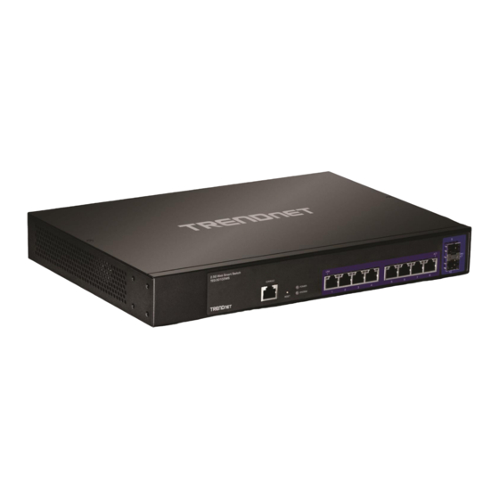
Product Overview TRENDnet’s 10-Port 2.5GBASE-T Web Smart+ Switch with eight 2.5GBASE-T ports and two 10G SFP+ slots, model TEG-30102WS, delivers advanced management features with an 80Gbps switching capacity. The TEG-30102WS is equipped with 2.5GBASE-T RJ-45 ports that provide higher gigabit speeds capable of up to 2.5Gbps over existing Cat5e or better cabling. -
Page 6: Product Hardware Features
Front View Console Port 2.5G/1G/100M Reset LED Indicators Ports Button SFP+ Slots Smart Fan – Smart fans will automatically adjust speed based on temperature and switch usage. The smart fans are hot swappable. © Copyright 2018 TRENDnet. All Rights Reserved. - Page 7 *If the System LED is flashing or on solid (orange) after normal switch operation, flashing will indicate an issue with the smart fan, solid will indicate an issue with switch. © Copyright 2018 TRENDnet. All Rights Reserved.
-
Page 8: Application Diagram
TRENDnet User’s Guide Application Diagram in an EIA standard-size, 19-inch rack The WebSmart switch is installed a server room with 2.5G web smart switch is providing 2.5G connectivity and VLAN support to existing network infrastructure. © Copyright 2018 TRENDnet. All Rights Reserved. -
Page 9: Switch Installation
When installing the Switch on a level surface, attach the rubber feet to the bottom of each device. The rubber feet cushion the hub and protect the hub case from scratching. Note: The look of the switch may be different than what is actually displayed. © Copyright 2018 TRENDnet. All Rights Reserved. -
Page 10: Basic Installation
Password: admin Note: User name and password are case sensitive. 9. Click Save Settings to Flash (button), then click OK. Note: Once the settings are saved, you can connect the switch to your network. © Copyright 2018 TRENDnet. All Rights Reserved. -
Page 11: Connect Additional Devices To Your Switch
Note: If you encounter issues connecting to your network, there may be a problem with your computer or device network settings. Please ensure that your computer or device network settings (also called TCP/IP settings) are configured properly within the network subnet your switch is connected. © Copyright 2018 TRENDnet. All Rights Reserved. -
Page 12: Configure Your Switch
DRAM Size: Displays your switch’s RAM memory size. Flash Size: Displays your switch’s Flash memory size. Temperature: Displays your switch’s current temperature Fan Status: Displays the status of your switch’s fans © Copyright 2018 TRENDnet. All Rights Reserved. - Page 13 System Contact – Displays the identifying system contact or system administrator of your switch. This information can be modified under the System section. System MAC Address, IPv4 Information MAC Address: Displays the switch system MAC address. © Copyright 2018 TRENDnet. All Rights Reserved.
-
Page 14: System
30 characters. System Contact - Specifies the name of the network administrator responsible for managing the switch. This contact name is optional and may contain up to 30 characters. © Copyright 2018 TRENDnet. All Rights Reserved. -
Page 15: Set Your Ipv4 Settings
DHCP Auto Configuration feature is available for this purpose via the DHCP server. Your IP address settings must enable the DHCP client so that this feature can operate with your DHCP server. © Copyright 2018 TRENDnet. All Rights Reserved. -
Page 16: Create And Assign Ipv4 Address Interfaces To Vlans
The new IPv4 interface and VLAN will appear in the table. Click Modify to edit the IPv4 interface address settings. When creating an IP address interface (IPv4 or IPv6), an entry is automatically created for both IPv4 and IPv6 address tables. © Copyright 2018 TRENDnet. All Rights Reserved. -
Page 17: Adding Ipv4 Static Arp Entries
Note: This step saves all configuration changes to the NV-RAM to ensure that if the switch is rebooted or power cycled, the configuration changes will still be applied. switch is rebooted or power cycled, the configuration changes will still be applied. © Copyright 2018 TRENDnet. All Rights Reserved. -
Page 18: Creating Ipv4 Static Routes
5. Click Save Settings to Flash (button), then click OK. Note: This step saves all configuration changes to the NV-RAM to ensure that if the switch is rebooted or power cycled, the configuration changes will still be applied. © Copyright 2018 TRENDnet. All Rights Reserved. -
Page 19: Set Your Ipv6 Settings
Nodes on a local link can use link-local addresses to communicate; the nodes do not need globally unique addresses to communicate. IPv6 devices must not forward packets that have link-local source or destination addresses to other links. © Copyright 2018 TRENDnet. All Rights Reserved. -
Page 20: Create And Assign Ipv6 Address Interfaces To Vlans
In this example, we will assign an IPv4 interface to VLAN 50. The new IPv6 interface and VLAN will appear in the table. Click Modify to edit the IPv6 interface address settings. By default, all IPv6 address interfaces are disabled. © Copyright 2018 TRENDnet. All Rights Reserved. -
Page 21: Add Ipv6 Neighbors
7. Click Save Settings to Flash (button), then click OK. Note: This step saves all configuration changes to the NV-RAM to ensure that if the switch is rebooted or power cycled, the configuration changes will still be applied. © Copyright 2018 TRENDnet. All Rights Reserved. -
Page 22: Creating Ipv6 Static Routes
IPv6 Network Address / Prefix Length: Enter the IPv6 destination network address and prefix. (e.g. fc10::/64) IPv6 Nexthop Address: Enter the IPv6 gateway address used to reach the destination IPv6 network. (e.g. fc00::1) 4. Click Save Settings to Flash (menu). © Copyright 2018 TRENDnet. All Rights Reserved. -
Page 23: Dns Settings
6. Click Save Settings to Flash (button), then click OK. When you have completed entering the IPv4 and IPv6 address entries, click the IP Restriction Status drop-down list at the top and select Enabled, then click Apply. © Copyright 2018 TRENDnet. All Rights Reserved. -
Page 24: Change Administrator Password And Add Accounts
Note: The password consists of up to 20 alphanumeric characters. 3. Review the settings. To change the administrator password, in the “admin” entry in the table, click on Modify. Note: This default administrator account cannot be deleted. © Copyright 2018 TRENDnet. All Rights Reserved. -
Page 25: Enable Or Disable Snmp And Modify Idle Timeout Settings
Web Idle Timeout - Enter the idle period in minutes, when the switch will automatically log out a user from the switch management page. 3. Review the settings. Click Apply to save changes. © Copyright 2018 TRENDnet. All Rights Reserved. -
Page 26: Set The Switch Date And Time
Clock Mode - Displays if system time and date is set manually Local Time or obtained automatically from a network time server SNTP. Current Time – Displays the current system time and date. Time Zone – Displays the current system time zone. © Copyright 2018 TRENDnet. All Rights Reserved. -
Page 27: Enable Https/Ssl (Secure Socket Layer) Management Access
1. Log into your switch management page (see “Access your switch management page” on page 11). 2. Click on System, and click on SSL Settings. © Copyright 2018 TRENDnet. All Rights Reserved. -
Page 28: View And Setup Your Switch Logging
Note: You can define the facility to store logging on your external syslog server. This helps to ensure you have separate logging sections for different devices. © Copyright 2018 TRENDnet. All Rights Reserved. -
Page 29: Physical Interface
SFP+ slots can be set to Auto, 10g/Full, or 1000/Full operation. and the end node connected to the port. The possible values are: Up -This parameter indicates a valid link exists between the port and the end node. © Copyright 2018 TRENDnet. All Rights Reserved. - Page 30 Flow Control field. In other words, each port is set individually. Enabled - This parameter indicates that the port is permitted to use flow control. Disabled - This parameter indicates that the port is not permitted to use flow control. © Copyright 2018 TRENDnet. All Rights Reserved.
-
Page 31: Spanning Tree (Stp, Rstp, Mstp)
Maximum Age: The Maximum Age defines the amount of time a port will wait for STP/RSTP information. MSTP uses this parameter when interacting with STP/RSTP domains on the boundary ports. Its range is 6 - 40 seconds © Copyright 2018 TRENDnet. All Rights Reserved. -
Page 32: Configure Spanning Tree Protocol Port Settings
'0' assigns the automatically calculated default Path Cost value to the status automatically. The default setting for this parameter is Auto. port. If the default Path Cost is being used, this object returns '0' when read. © Copyright 2018 TRENDnet. All Rights Reserved. -
Page 33: Configure Spanning Tree Protocol Mst Settings (Mstp)
Priority: Enter the new priority in the Priority field. The user may set a priority Note: This step saves all configuration changes to the NV-RAM to ensure that if the value between 0-61440. switch is rebooted or power cycled, the configuration changes will still be applied. © Copyright 2018 TRENDnet. All Rights Reserved. -
Page 34: View Your Spanning Tree Protocol Instance Information (Mstp)
5. Click Save Settings to Flash (button), then click OK. Note: This step saves all configuration changes to the NV-RAM to ensure that if the switch is rebooted or power cycled, the configuration changes will still be applied. © Copyright 2018 TRENDnet. All Rights Reserved. -
Page 35: Configure Spanning Tree Protocol Mst Port Settings (Mstp)
5. Click Save Settings to Flash (button), then click OK. Note: This step saves all configuration changes to the NV-RAM to ensure that if the switch is rebooted or power cycled, the configuration changes will still be applied. © Copyright 2018 TRENDnet. All Rights Reserved. -
Page 36: View Your Trunk Group Status Information
5. Click Save Settings to Flash (button), then click OK. Note: This step saves all configuration changes to the NV-RAM to ensure that if the switch is rebooted or power cycled, the configuration changes will still be applied. © Copyright 2018 TRENDnet. All Rights Reserved. -
Page 37: Configure Your Port Priority
Port section or you could click All to copy data received on all ports. To copy data transmitted on specific port, check the port number under the Egress Port section or you could click All to copy data transmitted on all ports. © Copyright 2018 TRENDnet. All Rights Reserved. -
Page 38: Loopback Detection
Recover Time – Defines the time period when connectivity will be restored to a switch is rebooted or power cycled, the configuration changes will still be applied. port where a loop was previously detected and blocked. Click Apply to save changes. © Copyright 2018 TRENDnet. All Rights Reserved. -
Page 39: Static Unicast
5. Click Save Settings to Flash (button), then click OK. Note: This step saves all configuration changes to the NV-RAM to ensure that if the switch is rebooted or power cycled, the configuration changes will still be applied. © Copyright 2018 TRENDnet. All Rights Reserved. -
Page 40: Static Multicast
Note: You can click All to select all ports. switch is rebooted or power cycled, the configuration changes will still be applied. Click Apply to add the Static Multicast Group entry to the list. © Copyright 2018 TRENDnet. All Rights Reserved. -
Page 41: Igmp Snooping
6. Click Save Settings to Flash (button), then click OK. Note: This step saves all configuration changes to the NV-RAM to ensure that if the switch is rebooted or power cycled, the configuration changes will still be applied. © Copyright 2018 TRENDnet. All Rights Reserved. -
Page 42: Configure Igmp Snooping Port Settings
Robustness Variable – Enter the robustness value used to determine the number of times to send a message. 5. Click Save Settings to Flash (menu). © Copyright 2018 TRENDnet. All Rights Reserved. -
Page 43: Configure Igmp Snooping Port Settings
5. Click Save Settings to Flash (button), then click OK. Note: This step saves all configuration changes to the NV-RAM to ensure that if the switch is rebooted or power cycled, the configuration changes will still be applied. © Copyright 2018 TRENDnet. All Rights Reserved. -
Page 44: Configure Igmp Snooping Address Entry
4. Click Apply. 5. Click Save Settings to Flash (menu). 5. You can review your settings under the IGMP Snooping Profile Table. 4. Click Apply. 6. Click Save Settings to Flash (button), then click OK. © Copyright 2018 TRENDnet. All Rights Reserved. -
Page 45: Mld Snooping
Compatibility – Click the drop-down to select Auto (automatically detect which IGMP version to use) or force the use of a specific IGMP version. Querier Interval – Enter the amount of time you want your switch to send IGMP queries. © Copyright 2018 TRENDnet. All Rights Reserved. -
Page 46: Configure Mld Snooping Port Settings
Bridge > MLD Snooping > Port Settings 1. Log into your switch management page (see “Access your switch management page” on page 11). 2. Click on Bridge, click on MLD Snooping, and click on Port Settings. © Copyright 2018 TRENDnet. All Rights Reserved. -
Page 47: Configure Mld Snooping Address Entry
4. Click Apply. 5. Click Save Settings to Flash (menu). 5. You can review your settings under the MLD Snooping Profile Table. 6. Click Save Settings to Flash (button), then click OK. 4. Click Apply. © Copyright 2018 TRENDnet. All Rights Reserved. -
Page 48: Bandwidth Control
Note: Modifying settings in the row marked All, will apply the settings to all ports. Broadcast – Click the drop-down list and select Enabled to enable broadcast storm control. Multicast – Click the drop-down list and select Enabled to enable multicast storm control. © Copyright 2018 TRENDnet. All Rights Reserved. -
Page 49: Set Egress Rate Limiting
Note: Modifying settings in the row marked All, will apply the settings to all 2. Click on Bridge, click on VLAN, and click on Tagged VLAN. ports. 3. Review the settings. VLAN ID – Enter the VLAN ID for the new VLAN. © Copyright 2018 TRENDnet. All Rights Reserved. - Page 50 VLAN aware. Select the tagged VLAN ports to add to the new VLAN. 4. Click Save Settings to Flash (menu). © Copyright 2018 TRENDnet. All Rights Reserved.
-
Page 51: Configure Vlan Port Settings
Disabled to disable ingress filtering. Note: Modifying settings in the row marked All, will apply the settings to all ports. 4. Click Save Settings to Flash (menu). 5. Click Save Settings to Flash (button), then click OK. © Copyright 2018 TRENDnet. All Rights Reserved. -
Page 52: View The Switch Vlan Dynamic Forwarding Table
Enable: Enable Private VLAN settings. Disable: Disable Private VLAN settings. Press Apply for changes to take effect. Set the Source Port to one of the following choices from the pull-down menu: All, 01 – 10. © Copyright 2018 TRENDnet. All Rights Reserved. -
Page 53: View The Current Vlan Database
Note: This step saves all configuration changes to the NV-RAM to ensure that if the switch is rebooted or power cycled, the configuration changes will still be applied. 2. Click on Bridge, click on VLAN, and click on Asymmetric VLAN. © Copyright 2018 TRENDnet. All Rights Reserved. - Page 54 6. Click Save Settings to Flash (button), then click OK. Note: This step saves all configuration changes to the NV-RAM to ensure that if the switch is rebooted or power cycled, the configuration changes will still be applied. © Copyright 2018 TRENDnet. All Rights Reserved.
-
Page 55: Qos (Quality Of Service)
Select Enabled in the QoS Status field. For each Traffic Class whose queue you want to change, click on the CoS Table (Low, Medium, High, or Highest) radio button that applies to your configuration. © Copyright 2018 TRENDnet. All Rights Reserved. -
Page 56: Set Port Priority
5. Click Save Settings to Flash (button), then click OK. Note: This step saves all configuration changes to the NV-RAM to ensure that if the switch is rebooted or power cycled, the configuration changes will still be applied. © Copyright 2018 TRENDnet. All Rights Reserved. -
Page 57: Set The Scheduling Algorithm
Note: This step saves all configuration changes to the NV-RAM to ensure that if the switch is rebooted or power cycled, the configuration changes will still be applied. © Copyright 2018 TRENDnet. All Rights Reserved. -
Page 58: Snmp
5. Click Save Settings to Flash (button), then click OK. Note: This step saves all configuration changes to the NV-RAM to ensure that if the switch is rebooted or power cycled, the configuration changes will still be applied. © Copyright 2018 TRENDnet. All Rights Reserved. -
Page 59: Configure The Snmp Group Access Table
Auth-Protocol has a password assigned and the Priv- Protocol has been selected as none on the SNMP User/Group page. AuthPriv: When the Auth-Protocol or Priv-Protocol have been enabled, choose this selection. Click the Add button. © Copyright 2018 TRENDnet. All Rights Reserved. -
Page 60: Configure The Snmp User/Group Table
Note: This step saves all configuration changes to the NV-RAM to ensure that if the none - Specifies no encryption is applied to SNMP data. switch is rebooted or power cycled, the configuration changes will still be applied. © Copyright 2018 TRENDnet. All Rights Reserved. -
Page 61: Configure The Snmp Community Table
Note: This step saves all configuration changes to the NV-RAM to ensure that if the Community table entry. switch is rebooted or power cycled, the configuration changes will still be applied. © Copyright 2018 TRENDnet. All Rights Reserved. -
Page 62: Configure The Snmp Trap Management
SNMP Community Table page. If you enter a Community Name that has not been pre-defined, the Trap Host entry is displayed, but agent/manager communication fails. Click Add. The new host is added to the table. © Copyright 2018 TRENDnet. All Rights Reserved. -
Page 63: Access Control Config
5. Click Save Settings to Flash (button), then click OK. Note: This step saves all configuration changes to the NV-RAM to ensure that if the switch is rebooted or power cycled, the configuration changes will still be applied. © Copyright 2018 TRENDnet. All Rights Reserved. - Page 64 Replaced-CoS or Replaced-DSCP to be processed by the switch. Note: You must enter a selection for Deny/Permit field even if the Profile Action ID that you have entered ignores both the Replaced- DSCP and Replaced-CoS fields. © Copyright 2018 TRENDnet. All Rights Reserved.
- Page 65 Enter a number in the Policy Index field. The Policy Index is a unique number within the range of 1 – 256 which identifies the policy. This field is mandatory. Mask Length – Indicates the length of the Sender IP Address ranging from 1 – 32 © Copyright 2018 TRENDnet. All Rights Reserved.
- Page 66 1 – 256 which identifies the policy. This field is mandatory. processed by the switch. Enter a number in the VLAN ID field. A unique number identifying a VLAN ranging from 1 to 4094. © Copyright 2018 TRENDnet. All Rights Reserved.
- Page 67 4. Click Save Settings to Flash (menu). range of 0 to 63. This field indicates the DSCP level of interest. This field is not mandatory and you may elect to leave it blank. © Copyright 2018 TRENDnet. All Rights Reserved.
-
Page 68: Configure Rate Control
This section allows you to enable or disable RMON functionality. 4. Click Save Settings to Flash (menu). 1. Log into your switch management page (see “Access your switch management page” on page 11). 2. Click on RMON and click on Global Settings. © Copyright 2018 TRENDnet. All Rights Reserved. -
Page 69: Configure Parameters For Rmon Ethernet Statistics
Note: This step saves all configuration changes to the NV-RAM to ensure that if the Port: This parameter specifies the port where you want to monitor the switch is rebooted or power cycled, the configuration changes will still be applied. statistical information of the Ethernet traffic. © Copyright 2018 TRENDnet. All Rights Reserved. -
Page 70: Configure Parameters For Rmon History Control Settings
Note: This step saves all configuration changes to the NV-RAM to ensure that if the and is an optional field. switch is rebooted or power cycled, the configuration changes will still be applied. © Copyright 2018 TRENDnet. All Rights Reserved. -
Page 71: Configure Parameters For Rmon Alarms
Event Index that you previously entered in “Events”. Owner: This parameter is used to identify the person who created an entry. It is primarily intended for switches that are managed by morethan one person, and is an optional field. © Copyright 2018 TRENDnet. All Rights Reserved. -
Page 72: Configure Parameters For Rmon Events
5. Click Save Settings to Flash (button), then click OK. Note: This step saves all configuration changes to the NV-RAM to ensure that if the switch is rebooted or power cycled, the configuration changes will still be applied. © Copyright 2018 TRENDnet. All Rights Reserved. -
Page 73: Voice Vlan
OUI. If the OUI of the remaining phones from that manufacturer is the same, then no other IP phone MAC addresses need to be entered into the configuration. © Copyright 2018 TRENDnet. All Rights Reserved. -
Page 74: Create A Voice Vlan
If the IP phone(s) that you are installing cannot be configured with a VLAN ID, then the after the last IP phone's OUI was received on a port, after which this switch ports should be configured as Static tagged ports within the voice VLAN. © Copyright 2018 TRENDnet. All Rights Reserved. -
Page 75: Configure Voice Vlan Oui Settings
The Status column displays Static for the member ports Enter a text description that helps you identify the manufacturer’s OUI in the User Defined OUI - Description field. This parameter can be up to 20 characters in length. © Copyright 2018 TRENDnet. All Rights Reserved. -
Page 76: Security
1. Log into your switch management page (see “Access your switch management page” switch is rebooted or power cycled, the configuration changes will still be applied. on page 11). 2. Click on Security and click on Port Access Control. © Copyright 2018 TRENDnet. All Rights Reserved. -
Page 77: Configure Port Access Settings
Port Control – Select the type of control being used (Auto, Force Authorized, Force Unauthorized) Authentication Mode – Select which authentication method for each port (802.1X, MAC Based) Supplicant Mode – Select the supplicant mode (Multiple, Single) © Copyright 2018 TRENDnet. All Rights Reserved. - Page 78 5. Click Save Settings to Flash (button), then click OK. Note: This step saves all configuration changes to the NV-RAM to ensure that if the switch is rebooted or power cycled, the configuration changes will still be applied. © Copyright 2018 TRENDnet. All Rights Reserved.
-
Page 79: Create Dial-In Users (Local Authentication Method)
If you enter 0, this field will be ignored. Click Add to add the entry to the table. © Copyright 2018 TRENDnet. All Rights Reserved. -
Page 80: Add Radius Servers (Radius Authentication Method)
1813. Shared Secret – Enter the default authentication and encryption key for RADIUS communication between the device and the RADIUS server. Click Add to add the entry to the table. © Copyright 2018 TRENDnet. All Rights Reserved. -
Page 81: Add Tacacs+ Servers (Tacacs+ Authentication Method)
Shared Secret – Enter the default authentication and encryption key for switch is rebooted or power cycled, the configuration changes will still be applied. TACACS+ communication between the device and the TACACS+ server. Click Add to add the entry to the table. © Copyright 2018 TRENDnet. All Rights Reserved. -
Page 82: Destination Mac Filter
1. Log into your switch management page (see “Access your switch management page” on page 11). 2. Click on Security and click on Destination MAC Filter. 3. Enter the MAC Address to add to the destination filter table. Click Add. © Copyright 2018 TRENDnet. All Rights Reserved. -
Page 83: Denial Of Service (Dos)
6. Click Save Settings to Flash (button), then click OK. Note: This step saves all configuration changes to the NV-RAM to ensure that if the switch is rebooted or power cycled, the configuration changes will still be applied. © Copyright 2018 TRENDnet. All Rights Reserved. -
Page 84: Arp Inspection
ARP entries, denied ARP entries, both permitted & denied (All), or no log entries (None). You can also check the Dynamic Entry Table, and add all dynamic entries discovered to the Static Entry Table list. © Copyright 2018 TRENDnet. All Rights Reserved. -
Page 85: Port Security Control
Violation Action/port state. Maximum Violation – This number is the maximum number of violations that will be allowed before applying the Violation Action/port state. © Copyright 2018 TRENDnet. All Rights Reserved. -
Page 86: Dhcp Snooping
DHCP Snooping - Select one of the following radio button choices: Enabled - This parameter activates the DHCP Snooping feature. Disabled - This parameter de-activates the DHCP Snooping 4. Click Save Settings to Flash (menu). © Copyright 2018 TRENDnet. All Rights Reserved. -
Page 87: Enable Dhcp Snooping
This section allows you to set trusted port interfaces where DHCP servers can be connected allows or denies DHCP server information to be received on those ports. 1. Log into your switch management page (see “Access your switch management page” on page 11). © Copyright 2018 TRENDnet. All Rights Reserved. -
Page 88: Dhcp Server
2. Click on DHCP, then click on DHCP Server, and click on Exclude IP Address. 3. Review the settings. Click Add to add the database entry to the table. Start IP Address: Enter the starting IP address to exclude from the DHCP server range. © Copyright 2018 TRENDnet. All Rights Reserved. - Page 89 5. Click Save Settings to Flash (button), then click OK. Note: This step saves all configuration changes to the NV-RAM to ensure that if the switch is rebooted or power cycled, the configuration changes will still be applied. © Copyright 2018 TRENDnet. All Rights Reserved.
-
Page 90: Dhcp Pool
First, Previous, Next, and Last Page to navigate the pages. Disabled – Blocks an Option 82 packet from passing through the switch Option 82 Policy – Select one of the following choices from the menu © Copyright 2018 TRENDnet. All Rights Reserved. -
Page 91: Lldp (Link-Layer Discovery Protocol)
Enable and configure LLDP LLDP > LLDP Global Settings 1. Log into your switch management page (see “Access your switch management page” on page 11). 2. Click on LLDP and click on LLDP Global Settings. © Copyright 2018 TRENDnet. All Rights Reserved. - Page 92 5. Click Save Settings to Flash (button), then click OK. Note: This step saves all configuration changes to the NV-RAM to ensure that if the switch is rebooted or power cycled, the configuration changes will still be applied. © Copyright 2018 TRENDnet. All Rights Reserved.
-
Page 93: View Lldp Neighbor Information
LLDP information is received from them. 2. Click on Statistic and click on Traffic Information. Port: This parameter specifies the TEG-30102WS local port number where the LLDP information was received. Chassis ID Subtype: This parameter describes the Chassis ID subtype of the 3. -
Page 94: View Error Information Statistics
Fragments: Number of fragments (packets with less than 64 octets, excluding framing bits, but including FCS octets) received. Collisions: Number of collisions received. If Jumbo Frames are enabled, the threshold of Jabber Frames is raised to the maximum size of Jumbo Frames. © Copyright 2018 TRENDnet. All Rights Reserved. -
Page 95: Switch Maintenance
TRENDnet may periodically release firmware upgrades that may add features or fix 2. Click on Tools, click on Firmware Upgrade, and click via HTTP. problems associated with your TRENDnet switch model and version. To check if there is a firmware upgrade available for your device, please check your TRENDnet model and 3. -
Page 96: Firmware Upgrade Via Tftp Settings
4. A separate file navigation window should open. 5. Select the router configuration file to restore and click Restore. (Default Filename: config.bin). If prompted, click Yes or OK. 6. Wait for the switch to restore settings. © Copyright 2018 TRENDnet. All Rights Reserved. -
Page 97: Backup/Restore Via Tftp Settings
TFTP Server IP: Enter the IP address of your TFTP server. config.bin) Config File Name: Enter the configuration file name for the backup. (Default: config.bin) 5. Wait for the switch to restore settings. © Copyright 2018 TRENDnet. All Rights Reserved. -
Page 98: Cable Diagnostics Test
2. Click on Tools and click on Cable Diagnostic. 3. Click on the Port drop-down list to select which port to run the cable diagnostic and click Test Now to run the test. © Copyright 2018 TRENDnet. All Rights Reserved. -
Page 99: Reboot/Reset To Factory Defaults
3. Click the Reboot Type drop-down list and select Normal and click Apply to initiate a reboot. Wait for the switch complete the rebooting process. The switch factory default settings are below. Administrator User Name admin Administrator Password admin Switch IP Address 192.168.10.200 Switch Subnet Mask 255.255.255.0 © Copyright 2018 TRENDnet. All Rights Reserved. -
Page 100: Network Connectivity Test (Ping Tool)
2. Click on Tools and click on Ping. 3. Review the settings. Click Start to start the network connectivity ping test. After the ping test is activate, you can click Show Ping Results to check the ping test result. © Copyright 2018 TRENDnet. All Rights Reserved. -
Page 101: Technical Specifications
Static unicast entries 802.1Q tagged VLAN LLDP Up to 32 VLAN groups, ID range 1-4094 IPv6 neighbor discovery, IPv6 static IP, and DHCPv6 Private VLAN Voice VLAN (16 user defined OUIs) MIB II RFC 1213 © Copyright 2018 TRENDnet. All Rights Reserved. - Page 102 Port Security/MAC address learning restriction (Up to 64 entries Rack mountable 1U height per port) Destination MAC filter Weight 2.33 kg (5.12 lbs.) Static/dynamic ARP inspection Certifications ACL IPv4 & IPv6 MAC address VLAN ID ARP/RARP EtherType ICMP type 1-255 © Copyright 2018 TRENDnet. All Rights Reserved.
-
Page 103: Troubleshooting
Click Internet Protocol Version (TCP/IPv4) and then click Properties. d. Then click Use the following IP address, and make sure to assign your network adapter an IP address in the subnet of 192.168.10.x. Click OK © Copyright 2018 TRENDnet. All Rights Reserved. -
Page 104: Appendix
From the Location drop-down list, select Automatic. 2. In the Network Preference window, next to "Show:", select Network Status. You'll see d. Select and view your Ethernet connection. your network status and your IP address settings displayed. © Copyright 2018 TRENDnet. All Rights Reserved. - Page 105 1. Apple Menu > System Preferences > Network 2. Select Ethernet from the list on the left. 3. Click the Advanced button. 3. On the Ethernet tab, the Ethernet ID is your MAC Address. © Copyright 2018 TRENDnet. All Rights Reserved.
- Page 106 Country Code selection feature to be disabled for products marketed to the US/CANADA CE Mark Warning This is a Class A product. In a domestic environment, this product may cause radio interference, in which case the user may be required to take adequate measures. © Copyright 2018 TRENDnet. All Rights Reserved.
- Page 107 An RMA number is required in order to initiate warranty service support the event that the RMA unit needs to be replaced, TRENDnet may replace it with a for all TRENDnet products. Products that are sent to TRENDnet for RMA service must refurbished product of the same or comparable model.
- Page 108 OF SUCH DAMAGES, AND LIMITS ITS LIABILITY TO REPAIR, REPLACEMENT, OR REFUND evidence of the original purchaser's date of purchase. Replacement products may be OF THE PURCHASE PRICE PAID, AT TRENDNET'S OPTION. THIS DISCLAIMER OF LIABILITY refurbished or contain refurbished materials. If TRENDnet, by its sole determination, is...