Table of Contents
Advertisement
Advertisement
Table of Contents

Related Manuals for TRENDnet TEG-3102WS


Summary of Contents for TRENDnet TEG-3102WS
- Page 1 Cover Page TRENDnet User’s Guide...
-
Page 2: Table Of Contents
Table of Contents TRENDnet User’s Guide Thank you for purchasing your new TRENDnet PoE Web Smart Switch! Table of Contents PoE Web Smart Switch Series Product Overview ......1 TEG-3102WS Overview ....................1 Package Contents ....................... 1 TPE-3102WS Hardware Features ..................1 Please note: The scope of this user's guide encompasses multiple TPE-3102WS Overview .................... - Page 3 MLD Snooping ......................49 IEEE 802.3az EEE ......................34 Global Settings ......................... 49 Enable IEEE 802.3az Power Saving Mode ................ 34 Fast Leave ........................49 VLAN Settings ........................50 Network..................35 Querier Settings ....................... 50 © Copyright 2022 TRENDnet. All Rights Reserved.
- Page 4 RADIUS ......................... 69 Port CoS ........................58 Add Radius Servers (RADIUS Authentication Method) ............ 69 Set Port Priority ........................ 58 TACACS+ ........................69 Bandwidth Control ....................... 59 Add TACACS+ Servers (TACACS+ Authentication Method) ..........69 © Copyright 2022 TRENDnet. All Rights Reserved.
- Page 5 Config Backup/Restore ....................75 Backup/Restore via HTTP Settings ................... 75 Backup/Restore via TFTP Settings ..................75 Diagnostics ........................76 Cable Diagnostics Test ..................... 76 Ping Test ........................77 Network Connectivity Test (Ping Tool) ................77 © Copyright 2022 TRENDnet. All Rights Reserved.
-
Page 6: Poe Web Smart Switch Series Product Overview
• SFP Slots (9-10) – Supports optional 10Gbps or 1Gbps mini-GBIC SFP modules for uplink or downlink connections. • Ground Point – Switch can be grounded from this point • DC-In © Copyright 2022 TRENDnet. All Rights Reserved. - Page 7 : When the Green LED lights on, the respective port is connected to a 100/1000Mbps Ethernet network. Green : When the LED is blinking green, the port is Blinking transmitting or receiving data on the network at 2.5Gbps speed. © Copyright 2022 TRENDnet. All Rights Reserved.
-
Page 8: Tpe-3102Ws Overview
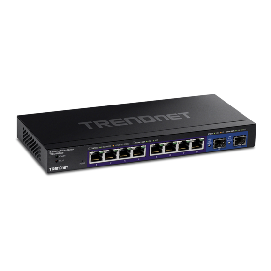
Ethernet Ports (1-8) – Connect either network PoE+ or non-PoE devices at 2.5Gbps / 1Gbps / 100Mbps speeds. • SFP Slots (9-10) – Supports optional 10Gbps or 1Gbps mini-GBIC SFP modules for uplink or downlink connections. © Copyright 2022 TRENDnet. All Rights Reserved. - Page 9 SFP Slots (9-10) PoE power budget. Green on : When the SFP LED is on, the link established using the SFP module is operating at 10Gbps • speed. Gigabit Ethernet PoE+ Port LEDs (1-8) © Copyright 2022 TRENDnet. All Rights Reserved.
-
Page 10: Tpe-3524S / Tpe-3524Sf Overview
• Power Cord (1.8m / 6 ft.) • Rack mount kit If any package contents are missing or damaged, please contact the retail store, online retailer, or reseller/distributor from which the product was purchased. © Copyright 2022 TRENDnet. All Rights Reserved. -
Page 11: Tpe-3524S / Tpe-3524Sf Hardware Features
SFP Slots (49-52) – Supports optional 10Gbps or 1Gbps mini-GBIC SFP When the PoE power provided is below the 240W modules for uplink or downlink connections. PoE power budget. • LAN Mode: Gigabit Ethernet PoE+ Port LEDs (1-48) © Copyright 2022 TRENDnet. All Rights Reserved. - Page 12 When the SFP LED is on, the link established using the SFP module is operating at 1000Mbps speed. When the SFP LED is on, the link established using the SFP module is operating at 10/100Mbps speed or there is no link © Copyright 2022 TRENDnet. All Rights Reserved.
-
Page 13: Teg-7124Ws Overview
Ethernet Ports (1-8) – Connect network devices at 10Gbps / 5Gbps 2.5Gbps / 1Gbps / 100Mbps speeds. • SFP Slots (9-12) – Supports optional 10Gbps or 1Gbps mini-GBIC SFP modules for uplink or downlink connections. © Copyright 2022 TRENDnet. All Rights Reserved. - Page 14 : When the Green LED lights on, the respective port is connected to a 100/1000Mbps Ethernet network. Green : When the LED is blinking green, the port is Blinking transmitting or receiving data on the network at 2.5/5/10Gbps speed. © Copyright 2022 TRENDnet. All Rights Reserved.
-
Page 15: Teg-3524S Overview
2.5Gbps / 1Gbps / 100Mbps speeds. retailer, or reseller/distributor from which the product was purchased. • SFP Slots (49-52) – Supports optional 10Gbps or 1Gbps mini-GBIC SFP modules for uplink or downlink connections. © Copyright 2022 TRENDnet. All Rights Reserved. - Page 16 When the LED is blinking green, the port is Blinking transmitting or receiving data on the network. Green When the LED is solid green, there is a Solid connection between the device and the switch © Copyright 2022 TRENDnet. All Rights Reserved.
-
Page 17: Switch Installation
• When installing the Switch on a level surface, attach the rubber feet to the bottom of each device. The rubber feet cushion the hub and protect the hub case from scratching. Then, use screws provided with the equipment rack to mount each switch in the rack. © Copyright 2022 TRENDnet. All Rights Reserved. -
Page 18: Setup Wizard
Note: Configuration with TRENDnet Hive Cloud Management requires an existing network with Internet access and DHCP server for automatic IP addressing. The switch must be configured to reach the Internet in order to connect to your TRENDnet Hive Cloud Management account. - Page 19 7. After selecting TRENDnet Hive, click Next and change your computer’s network 10. To verify the switch is now successfully registered with your TRENDnet Hive Cloud adapter settings to obtain an IP address automatically to continue the rest of the setup Management account, the Hive button in the top right will be green to indicate wizard.
- Page 20 7. Configure the switch date and time settings, then click Next. 8. Configure the switch IP address, subnet mask, gateway IP address, and DNS settings to match the requirements of your existing network using the fields provided, then click Next. © Copyright 2022 TRENDnet. All Rights Reserved.
-
Page 21: Basic Ip Configuration
192.168.10.x (e.g. 192.168.10.25) and a subnet mask of 255.255.255.0. 4. Open your web browser, and type the IP address of the switch in the address bar, and then press Enter. The default IP address is 192.168.10.200. © Copyright 2022 TRENDnet. All Rights Reserved. - Page 22 Note: All other functions of this page will be explained in detail in its respective section. Note: Be sure to re-log back into the switch using the new IP address and save the configuration to your flash. © Copyright 2022 TRENDnet. All Rights Reserved.
-
Page 23: Connect Additional Devices To Your Switch
Note: If you encounter issues connecting to your network, there may be a problem with your computer or device network settings. Please ensure that your computer or device network settings (also called TCP/IP settings) are configured properly within the network subnet your switch is connected. Note: Your switch model may be different than the one shown in the example illustrations. © Copyright 2022 TRENDnet. All Rights Reserved. -
Page 24: Access Your Switch Management Page
• DRAM Size: Displays your switch RAM memory size. • Flash Size: Displays your switch Flash memory size. • Fan Status: Displays the current status of your switch’s fan • Hardware Version: Displays your switch’s current hardware version © Copyright 2022 TRENDnet. All Rights Reserved. - Page 25 • QoS: Displays if your switch has QoS enabled or disabled • DoS: Displays if your switch has DoS enabled or disabled • IPv4 DHCP Client Mode: Displays if your switch IPv4 address setting is set to DHCP client. © Copyright 2022 TRENDnet. All Rights Reserved.
-
Page 26: Real-Time Statistics
2. Click on Dashboard, then click on Real-time Statistics. The switch view shows the ports that are connected. Select Status, Duplex, Speed, or PoE to display which ports are currently using the selected feature. System System Settings Set your system information System > System Settings © Copyright 2022 TRENDnet. All Rights Reserved. - Page 27 255 characters. • System Contact - Specifies the name of the network administrator responsible for managing the switch. This contact name is optional and may contain up to 255 characters. © Copyright 2022 TRENDnet. All Rights Reserved.
-
Page 28: L3 Feature
VLAN. 5. Review the settings. When you have completed making changes, click Apply to save the settings. • VLAN: Select the VLAN ID you wish to configure. . © Copyright 2022 TRENDnet. All Rights Reserved. -
Page 29: Ipv4 Arp Aging Time
5. Click the Apply button on the top right of the screen. Note: This step saves all configuration changes to the NV-RAM to ensure that if the switch is rebooted or power cycled, the configuration changes will still be applied. © Copyright 2022 TRENDnet. All Rights Reserved. -
Page 30: System Time
1. Log into your switch management page (see “Access your switch management page” on page 5). 2. Click on System, then click on System Settings, and click on System Time. 3. Review the settings below and click Apply to save your settings. © Copyright 2022 TRENDnet. All Rights Reserved. -
Page 31: Snmp
1. Log into your switch management page (see “Access your switch management page” on page 5). 2. Click on System, click on SNMP, and click on Global Settings. • User Name: Enter the User Name to grant access to © Copyright 2022 TRENDnet. All Rights Reserved. -
Page 32: Community List
Community Name: Input the community name for the new entry on page 5). • Security Name: Select the security type • Transport Tag: Input the transport tag in the field 2. Click on System, click on SNMP, and click on Access List. © Copyright 2022 TRENDnet. All Rights Reserved. -
Page 33: View List
2. Click on System, click on RMON, and click on Stat List. 3. Select Edit to edit the selected group name or Delete to delete it. 3. Click Add to add the entry to the table © Copyright 2022 TRENDnet. All Rights Reserved. -
Page 34: Event List
Event group— This group is used with alarms to define the actions of the • switch when packet statistic thresholds are crossed. Index: This parameter specifies the ID number of the new group. The range is 1 to 65535. © Copyright 2022 TRENDnet. All Rights Reserved. -
Page 35: Event Log Table
The alert messages can take • Rising Threshold: This parameter specifies a specific value or threshold level of the monitored statistic. When the value of the monitored statistic becomes © Copyright 2022 TRENDnet. All Rights Reserved. -
Page 36: History
Click Add to add the entry to the table. History System > RMON > History List © Copyright 2022 TRENDnet. All Rights Reserved. -
Page 37: History Log Table
5). 2. Click on System, click on MAC Address Table, and click on Static MAC Address. 3. Click Add to configure a new static MAC address 4. Review the settings and click Apply. © Copyright 2022 TRENDnet. All Rights Reserved. -
Page 38: Dynamic Mac Address
System > MAC Address Table > MAC Aging Time 1. Log into your switch management page (see “Access your switch management page” on page 5). 2. Click on System, click on MAC Address Table, and click on MAC Aging Time. © Copyright 2022 TRENDnet. All Rights Reserved. -
Page 39: Ieee 802.3Az Eee
IEEE 802.3az EEE function. Users can enable this feature via the IEEE802.3az EEE setting page. 1. Log into your switch management page (see “Access your switch management page” on page 5). 2. Click on Tools and click on EEE. © Copyright 2022 TRENDnet. All Rights Reserved. -
Page 40: Physical Interface
You can use this parameter to set the speed and duplex mode of a port. Disabled - This parameter indicates that the port is not permitted to The possible settings are: use flow control. © Copyright 2022 TRENDnet. All Rights Reserved. -
Page 41: Port Isolation
• Destination Port – Click the drop-down and list and select the port to send the copied ingress/egress packets/data. (e.g. Computer or device with packet capture or data analysis program.) © Copyright 2022 TRENDnet. All Rights Reserved. -
Page 42: Jumbo Frames
This section lets you input the size of the Jumbo Frames that can be accepted by the switch. 1. Log into your switch management page (see “Access your switch management page” on page 5). © Copyright 2022 TRENDnet. All Rights Reserved. -
Page 43: Vlan Settings
Name – Enter the VLAN name. Note: By default, the default VLAN VID 1 is set as the Management VLAN. • Cancel – Deletes the current settings • Apply – Apply the new settings © Copyright 2022 TRENDnet. All Rights Reserved. -
Page 44: Pvid & Ingress Filter
Untagged– The port can accept untagged frames and frames with tagged priority information only such as 802.1p. Note: Modifying settings in the row marked All, will apply the settings to all ports. © Copyright 2022 TRENDnet. All Rights Reserved. -
Page 45: Gvrp
GARPLeaveTimer >= (GARPJoinTimer X 2) + 10 3. Select Enabled under GARP VLAN Registration Protocol to to activate GVRP or disabled to deactivate GVRP. Click Apply to save the settings. © Copyright 2022 TRENDnet. All Rights Reserved. -
Page 46: Spanning Tree
BPDUs that the bridge can send per second. Its range is 1 - 10. • Hello Time: The Hello Time is frequency with which the root bridge sends out a BPDU. © Copyright 2022 TRENDnet. All Rights Reserved. -
Page 47: Root Bridge Information
1. Log into your switch management page (see “Access your switch management page” on page 5). 2. Click on Network, click on Spanning Tree, click on Global Settings, and click on Root Bridge Information. © Copyright 2022 TRENDnet. All Rights Reserved. -
Page 48: Cist Port Settings
Selecting Yes indicates a P2P shared link is available. Selecting No means the port cannot maintain a P2P link. • Migration: Enabled indicates the port is configured to accept RSTP and Disabled indicates the port is not configured to accept RSTP. © Copyright 2022 TRENDnet. All Rights Reserved. -
Page 49: Mst
Priority: Select the new priority in the Priority field from the drop down menu 1. Log into your switch management page (see “Access your switch management page” options. The user may set a priority value between 0-61440. on page 5). © Copyright 2022 TRENDnet. All Rights Reserved. -
Page 50: Mst Port Settings
Internal Path Cost (0 = Auto) - This is the port cost used by MSTP when calculating path cost to the root bridge. Port Status: Enable or disable the current settings configured for the selected port. © Copyright 2022 TRENDnet. All Rights Reserved. -
Page 51: Trunk
Data Unit) packets. This setting enables the dynamic LACP feature for the trunk. • Static - Enables static port trunking and disables the LACP feature for the trunk. (Static link aggregation). • Disable - Disables the static port trunk and disables the LACP feature. © Copyright 2022 TRENDnet. All Rights Reserved. -
Page 52: Lacp Timeout
• Fast Leave – Select Enabled to enable Fast Leave from the selected port or switch is rebooted or power cycled, the configuration changes will still be applied. Disabled to disable the feature © Copyright 2022 TRENDnet. All Rights Reserved. -
Page 53: Vlan Settings
IGMP Snooping Status – Click the drop-down list and select Enabled to enable the IGMP snooping or Disabled to disable the feature • Version – Click the drop-down list and select IGMP version Querier Settings Network > IGMP Snooping > Querier Settings © Copyright 2022 TRENDnet. All Rights Reserved. -
Page 54: Router Settings
2. Click on Network, click on MLD Snooping, and click on Port Settings. 3. Review the settings. Click Apply to save the settings. • Fast Leave – Select Enabled to enable Fast Leave from the selected port or Disabled to disable the feature © Copyright 2022 TRENDnet. All Rights Reserved. -
Page 55: Vlan Settings
Version – Click the drop-down list and select IGMP version Router Settings Network > MLD Snooping > Router Settings 1. Log into your switch management page (see “Access your switch management page” on page 5). © Copyright 2022 TRENDnet. All Rights Reserved. -
Page 56: Loopback Detection
The switch identifies a voice data packet by comparing the OUI information in the packet’s source MAC address with an OUI table that you configure when you initially 4. At the top right panel, click the Apply button to save the changes to the Flash. © Copyright 2022 TRENDnet. All Rights Reserved. -
Page 57: Global Settings
These ports might be connected to other voice VLAN network nodes such as other • VLAN Priority Tag – This parameter sets the priority of the VLAN. The priority is configured through the pull-down menu. © Copyright 2022 TRENDnet. All Rights Reserved. -
Page 58: Oui Settings
2. Click on Network, click on Voice VLAN, and click on OUI Settings. • State – Select Enabled to enable COS mode or Disabled to disable this feature. • CoS Mode – Select Src mode or All © Copyright 2022 TRENDnet. All Rights Reserved. -
Page 59: Lldp
System Name: This parameter lists the System Name of the switch. You can assign the system name from System Settings. • System Description: This parameter lists the product name of the switch. You cannot change this parameter © Copyright 2022 TRENDnet. All Rights Reserved. -
Page 60: Multicast Filtering
Password: Set the password for this new username on page 5). • Password Retype: Re-type your password. 2. Click on Network and click on Multicast Filtering. 3. Select Enabled to enable this feature or Disabled to disable Multicast Filtering © Copyright 2022 TRENDnet. All Rights Reserved. -
Page 61: Logs
4. Review the settings and click Apply to save the changes to the Flash. • IP/Hostname: Enter the IP address of the location you want the Log files to go When a port on an Ethernet switch becomes oversubscribed, its egress © Copyright 2022 TRENDnet. All Rights Reserved. -
Page 62: Global Settings
WRR (Weighted RoundRobin) - The port transmits a set number of packets from each queue, in a round robin fashion, so that each has a chance to transmit traffic. 4. Select the Trust Mode: © Copyright 2022 TRENDnet. All Rights Reserved. -
Page 63: Dscp Mapping
4. At the bottom of the left hand panel, click Apply. Note: This step saves all configuration changes to the NV-RAM to ensure that if the switch is rebooted or power cycled, the configuration changes will still be applied. © Copyright 2022 TRENDnet. All Rights Reserved. -
Page 64: Bandwidth Control
Note: Modifying settings in the row marked All, will apply the settings to all • Egress – Select Enabled to enable Egress Rate Limiting or Disabled to disable ports. this feature. • Egress Rate (kbps) – Enter the egress rate limit value. © Copyright 2022 TRENDnet. All Rights Reserved. -
Page 65: Poe (Power Over Ethernet)
Maximum Power level is the default setting. Class Output Power Ranges of the PDs from a Switch Port 15.4W 0.44W to 12.95W 4.0W 0.44W to 3.84W 7.0W 3.84W to 6.49W 15.4W 6.49W to 12.95W © Copyright 2022 TRENDnet. All Rights Reserved. -
Page 66: Configure Poe Budget
State - The PoE port status is given as follows: ON - The port is supplying PoE power. OFF - The port is not supplying PoE power. • Priority - Indicates the port priority: Low, High, or Critical. © Copyright 2022 TRENDnet. All Rights Reserved. -
Page 67: Flick Reboot
Note: This step saves all configuration changes to the NV-RAM to ensure that if the Note: By default, Flick Reboot is set to Disabled. switch is rebooted or power cycled, the configuration changes will still be applied © Copyright 2022 TRENDnet. All Rights Reserved. -
Page 68: Pd Lifeguard
4. At the bottom of the left hand panel, click Apply to save the settings to the flash. . • Ping Interval: Enter the desired time for how often the switch will send a ping to the connected device © Copyright 2022 TRENDnet. All Rights Reserved. -
Page 69: Security
Note: By default, the timeout duration is set to 30 minutes. • Telnet Service: Select Enabled to enable Telnet or Disabled to disable this feature. © Copyright 2022 TRENDnet. All Rights Reserved. -
Page 70: Port Security
3. Review the settings below and click Apply to save your settings. • ACL Name: Select the ACL name you would like to configure. • Sequence: • Action: Defines the ACl action linked to the rule criteria. © Copyright 2022 TRENDnet. All Rights Reserved. -
Page 71: Access Control: Creating Ipv4 Acl
0 to 63. This field indicates the DSCP level of interest. This field is not 2. Click on Security, then click on Access Control, and click on IPv4 ACL. mandatory and you may elect to leave it blank. © Copyright 2022 TRENDnet. All Rights Reserved. -
Page 72: Access Control: Creating Ipv6 Acl
• Destination IP: Input the destination IP address 2. Click on Security, then click on Access Control, and click on IPv6 ACL. • Source IP: Input the source of the IP address © Copyright 2022 TRENDnet. All Rights Reserved. -
Page 73: Port Binding
4. Select from the list of ACLs and click Apply to save your settings. • In the Password field, type a password for the user. • In the Password Retype field, re-type the password to confirm. Click Apply to add the entry to the table. © Copyright 2022 TRENDnet. All Rights Reserved. -
Page 74: Radius
1. Log into your switch management page (see “Access your switch management page” default port is 1813. on page 5). • Key String – Enter the default authentication and encryption key for RADIUS © Copyright 2022 TRENDnet. All Rights Reserved. -
Page 75: Dhcp Snooping
Disable - The MAC address of each ingress ARP packet is not validated against the Binding Table. All ARP packets are forwarded through the switch without regard to the IP and MAC Address information in the packet header. © Copyright 2022 TRENDnet. All Rights Reserved. -
Page 76: Vlan
Untrusted: This parameter defines the port as untrusted for the DHCP Snooping feature. • Trusted: This parameter defines the port as trusted for the DHCP Snooping feature. Note: You can select the row labeled ALL to apply settings to all ports. © Copyright 2022 TRENDnet. All Rights Reserved. -
Page 77: Denial Of Service
1. Log into your switch management page (see “Access your switch management page” on page 5). 2. Click on Security and click on DoS 3. Select Enabled to enable DoS or Disabled to disable DoS. © Copyright 2022 TRENDnet. All Rights Reserved. -
Page 78: Tools
TRENDnet may periodically release firmware upgrades that may add features or fix 3. Select the firmware Upgrade Method (HTTPS or TFTP). problems associated with your TRENDnet switch model and version. To check if there is a firmware upgrade available for your device, please check your TRENDnet model and 4. -
Page 79: Dual Image
Created Time: When the firmware was loaded onto the partition • File Name: Enter the firmware filename with extension. (.hex) 6. Click Apply to start the firmware upgrade. Dual Image Tools > Firmware > Dual Image © Copyright 2022 TRENDnet. All Rights Reserved. -
Page 80: Config Backup Restore
3. Make sure your TFTP server is running and note the IP address of your server and firmware file name. The TFTP server should be in the same IP subnet as the switch. © Copyright 2022 TRENDnet. All Rights Reserved. -
Page 81: Diagnostics
3. The test also measures the cable fault and identifies the fault in length Method: Select TFTP as the method of restoring up your configuration according to the distance from the switch. • TFTP Server IP: Enter the IP address of your TFTP server © Copyright 2022 TRENDnet. All Rights Reserved. -
Page 82: Ping Test
This chapter provides the procedure to ping a node on your network from the switch. This procedure is useful in determining whether an active link exists between the switch and another network device. © Copyright 2022 TRENDnet. All Rights Reserved. -
Page 83: Ipv6 Ping Test
Note: You may want to save the settings to flash before reboot the switch under Save Settings to Flash (menu) > Save Settings to Flash (button). If you have not saved your current configuration settings to flash first, the configuration changes will be lost after a reboot. © Copyright 2022 TRENDnet. All Rights Reserved. - Page 84 Hardware Method: Using a paper clip, on the front panel of the switch, push and hold the Reset button more than 6 seconds and release. Located on the front panel of your switch, see “Product Hardware Features” on page 2. Use © Copyright 2022 TRENDnet. All Rights Reserved.
-
Page 85: Hardware Features And Specifications
802.3at: Up to 30W per port port PoE Budget 240W 410W 740W Fan Quantity Fanless 1 x Smart Fan 1 x Smart Fan 1 x Smart Fan 3 x Smart Fans 3 x Smart Fans © Copyright 2022 TRENDnet. All Rights Reserved. - Page 86 664g (1.46 lbs.) 2.265kg (4.99 lbs.) 1.96kg (4.31 lbs.) 3.408kg (7.51lbs.) 4.75kg (10.46lbs.) 4.75kg (10.46lbs.) Certifications External Power Adapter (UL) MTBF 893,900 hours 342,000 hours 53,900 hours 252,000 hours 37,300 hours 37,300 hours © Copyright 2022 TRENDnet. All Rights Reserved.
-
Page 87: Web Smart Switch Series Software Specifications
• Link Aggregation Static Link Aggregation 802.3ad Dynamic LACP • • • 802.1p Class of Service (CoS) Bandwidth Control per port Queue Scheduling: Strict Priority, Quality of Service (QoS) Weighted Round Robin (WRR) © Copyright 2022 TRENDnet. All Rights Reserved. - Page 88 • IPv4 / IPv6 static routing Routing table entries: Up to 32 (IPv4 / Inter-VLAN routing IPv6) • Layer 3 Features IP interfaces: Up to 6 • ARP table (up to 128 entries) © Copyright 2022 TRENDnet. All Rights Reserved.
-
Page 89: Quick Installation Guide Troubleshooting
Then click Use the following IP address, and make sure to assign your network adapter an IP address in the subnet of 192.168.10.x. Click OK Note: If you are experiencing difficulties, please contact your computer or operating system manufacturer for assistance. © Copyright 2022 TRENDnet. All Rights Reserved. - Page 90 2. In the Network Preference window, next to "Show:", select Network Status. You'll see c. From the Location drop-down list, select Automatic. your network status and your IP address settings displayed. d. Select and view your Ethernet connection. © Copyright 2022 TRENDnet. All Rights Reserved.
- Page 91 2. Select Ethernet from the list on the left. Example: ping –c 4 192.168.10.100 3. Click the Advanced button. 3. On the Ethernet tab, the Ethernet ID is your MAC Address. © Copyright 2022 TRENDnet. All Rights Reserved.
- Page 92 Country Code selection feature to be disabled for products marketed to the US/CANADA CE Mark Warning This is a Class A product. In a domestic environment, this product may cause radio interference, in which case the user may be required to take adequate measures. © Copyright 2022 TRENDnet. All Rights Reserved.
- Page 93 An RMA number is required in order to initiate warranty service support the event that the RMA unit needs to be replaced, TRENDnet may replace it with a for all TRENDnet products. Products that are sent to TRENDnet for RMA service must refurbished product of the same or comparable model.
- Page 94 TRENDnet User’s Guide prepaid, insured and packaged appropriately for safe shipment. International customers LIMITATION OF LIABILITY: TO THE FULL EXTENT ALLOWED BY LAW, TRENDNET ALSO shipping from outside of the USA and Canada are responsible for any return shipping EXCLUDES FOR ITSELF AND ITS SUPPLIERS ANY LIABILITY, WHETHER BASED IN and/or customs charges, including but not limited to, duty, tax, and other fees.