Table of Contents
Advertisement
Quick Links
Advertisement
Chapters
Table of Contents
Troubleshooting

Related Manuals for Datamax Prodigy Plus


Summary of Contents for Datamax Prodigy Plus
- Page 1 Prodigy Plus ™ Operator’s Manual...
- Page 2 PLC, is a product of Agfa Corporation. Futura is a registered trademark of Fundición Tipográfica Neufville, S.A. Prodigy Plus, Prodigy Plus 152, SEAQ, and PC Batch are trademarks of Datamax Barcode Products Corporation. As an Energy Star Partner, Datamax Corporation has determined that this product meets the Energy Star guidelines for energy efficiency.
- Page 3 Agency Compliance and Approvals: UL1950 Information Technology Equipment, file number E156091. CSA: C22.2 No. 950-M1986, file number LR68943-13. TUV-GS: EN60950/03.88, certificate number S9371819. VDE: Class B Vfg. 1046/1984. 1. Nur für Gebrauch innerhalb eines Gebäudes geeignet. 2. Bei Gefahr, Kabel aus der Steckdose herausziehen 3.
- Page 5 Important Safety Instructions Your Barcode Printer has been designed to give you many years of safe, reliable service. As with all electrical equipment, there are a few basic precautions you should take to avoid getting hurt or damaging the Printer. •...
-
Page 7: Table Of Contents
♦ Contents ♦ Getting Started 1.0 Introduction..............1 1.1 Unpacking and Inspection ...........2 1.2 Supplies Necessary to Print Labels.......2 1.3 Location of Parts on your Printer.........3 1.4 Installing the Front Door ..........5 1.5 Using the Printer’s Control Panel.........6 1.6 Using Print Media ............8 1.7 Media Rewind Instructions ........10 1.7.1 Peel-off Mode ..........11 1.8 Ribbon Loading Instructions ........12... - Page 8 ♦ Maintenance 4.0 Cleaning the Printer ...........37 4.1 Cleaning the Printhead..........38 ♦ Appendix A ASCII Control Code Chart..........A-1 ♦ Appendix B Switch Settings and Cable Interfacing ......B-1 ♦ Appendix C Available Fonts and Barcodes .........C-1 ♦ Appendix D Error Codes..............D-1 ♦...
-
Page 9: Getting Started
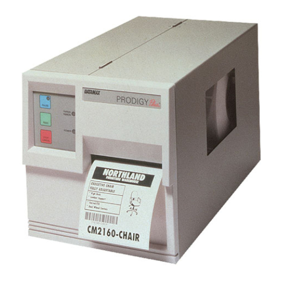
♦ Getting Started Figure 1-1 Printer Overview 1.0 Introduction The Prodigy Plus, hereafter referred to as the “Printer”, incorporates high-performance/low cost thermal label printing capabilities. The combination of powerful capabilities, easy-to-use features, a contemporary look and affordable pricing set a new standard for thermal label printing in retail, office and industrial applications. -
Page 10: Unpacking And Inspection
In order for the Printer to generate labels you will need the necessary software and media. There are many different types of media and software packages available, therefore it is a good idea to contact your local reseller on which software and media is best suited for your needs. Prodigy Plus... -
Page 11: Location Of Parts On Your Printer
The following illustrations show the major components of your Printer. Figure 1-2 is the front panel with the cover open, Figure 1- 3 is the mechanism detail and Figure 1-4 is the rear view. Figure 1-2 Front Panel (Front Cover Open) Prodigy Plus... - Page 12 Getting Started Figure 1-3 Mechanism Detail Figure 1-4 Rear View Prodigy Plus...
-
Page 13: Installing The Front Door
Complete the following steps when installing the front door. 1. Remove the door and Printer from its packaging. 2. With the hinges lined up to the proper location on the Printer, gently slide the door into the Printer’s hinge slots. Figure 1-5 Installing the Door Prodigy Plus... -
Page 14: Using The Printer's Control Panel
Printer is activated. Pause Light: This light will turn on if any of the following occurs: the Pause Button is pressed; a print job is canceled with the Stop/CancelButton, or; a fault occurs with the Cutter. Prodigy Plus... - Page 15 Printhead temperature is reduced, since most Thermal-Transfer Printing does not require as much heat as Direct-Thermal Printing. Darkness Control This potentiometer (POT) is used to fine adjust POT: darkness to variations in the media. Prodigy Plus...
-
Page 16: Using Print Media
1. Slide the Media Retainer to outer end of Media Supply Mount. 2. Place the new media supply roll on the Media Supply Mount and slide the Media Retainer firmly back against it. Figure 1-7 Media Supply Mount Prodigy Plus... - Page 17 ‘Feed’ button and does not seem to be stopping on a label’s edge, the Thermal/Thermal Transfer switch has probably been turned on without thermal-transfer ribbon being installed. Slide the switch back to the left side for direct-thermal printing. Prodigy Plus...
-
Page 18: Media Rewind Instructions
Getting Started 1.7 Media Rewind Instructions 1. Remove the window cover from the front door. 2. Fasten the rewind adapter to the front of the Printer as shown in Figure 1-9. Figure 1-9 Attaching the Rewind Adapter Prodigy Plus... -
Page 19: Peel-Off Mode
Note: Do not install the rewind adapter when using the Peel-off Mode. Using the Peel-off Mode without the Present Sensor installed and enabled can cause labels to become jammed in the Printer. Caution Prodigy Plus... -
Page 20: Ribbon Loading Instructions
4. Ensure that the Transfer Switch is in the ‘on’ position. Note: If using a ribbon that is translucent, (i.e., color other than black), it may be necessary to turn on switch 1-7 located on the back of the Printer. Prodigy Plus... -
Page 21: Printing Labels
The attention getter character is followed by a command character that tells the Printer what action to take. ASCII Decimal Attention Getter For Char. Value Value Prompt Ctrl A Immediate Commands Ctrl B System-Level Commands Ctrl [ Font-Loading Commands Table 2-1 Attention Getters Prodigy Plus... - Page 22 3. Parameters that must be entered by the user (if any). Command Must Enter Printer Command Character Parameters Responds Reset Send ASCII status string Toggle pause Cancel SOH shutdown Send batch quantity Send status byte Table 2-2 Immediate Commands Prodigy Plus...
- Page 23 Where: nn plus or minus (.50 inches in hundredths of an inch increments) Test RS-232 Port Y=ok Sends character "Y" to RS-232 port Enter Label Formatting Mode Set maximum label length Mnnnn = 4 digits (default) Table 2-3 System-Level Commands Prodigy Plus...
- Page 24 Test FLASH module memory Takes about 90 seconds Set default module bank Xa a - A = Memory Module A Output sensor values Dumps sensor values status to RS-232 port Print internal information and dot pattern Table 2-3 System-Level Commands (Continued) Prodigy Plus...
- Page 25 B =Memory Module B C= Default Module nn...n - label name (16 char. max) Set field data line terminator Tnn nn = 2 digit ASCII Hex 00 - FF Make previous field a string replace field Table 2-4 Label-Formatting Commands Prodigy Plus...
- Page 26 Commands. Unlike the other Label-Formatting Commands, which follow the STX L Command, these special commands are entered directly into the data field. Character Description <STX>S Recall global data and place in field <STX>T Print time and date Table 2-5 Special Label-Formatting Commands Prodigy Plus...
-
Page 27: Programming Examples
CC = Command Character P = Must Supply Parameters? (Y/N) PR = Printer Responds? (Y/N) 2.2 Programming Examples <STX> L <CR> H07 <CR> D11 <CR> 19110080100002510K OHM 1/4 WATT <CR> 1a6210000000050590PCS <CR> 10K OHM 1/4 WATT Figure 2-1 Sample Label Prodigy Plus... - Page 28 Refer to Figures 2-2 and 2-3 for a brief explanation of the data fields that appear in the barcode shown below. <STX>L<CR> D11<CR> 1A93040001501000123456789<CR> 121100000000100Barcode A<CR> <STX>L <STX>L on line 1 is used to enter the label formatting mode. Figure 2-2 Example line 3 Figure 2-3 Example line 4 Prodigy Plus...
-
Page 29: Configuration And Test Labels
SETUP SWITCH 1 OFF OFF OFF OFF OFF OFF OFF OFF ANALOG INPUT VALUES: PAPER: 236 EDGE: 184 TEMP POT ADJ: 139 BAT VOL: 204 INCH COUNTER DATE SET 4/07/97 TOTAL LABEL LENGTH IN INCHES 000000170 Figure 2-4 Configuration Label Prodigy Plus... -
Page 30: Print Test Label
Below are examples of the Loop Back Test Plugs. If the Test Plug is installed the following two lines will be added to the Configuration Label. SERIAL LOOP BACK CHECK GOOD CTS & DTR LOOP BACK CHECK IS GOOD Figure 2-6 Loop Back Test Plugs Prodigy Plus... -
Page 31: Troubleshooting
It also provides basic ideas to help identify common installation and communication interfacing problems. If there is any doubt about your ability to perform the procedures outlined in this chapter, contact a qualified service technician before making any adjustments. Prodigy Plus... -
Page 32: Controlling Print Quality
However, when using media other than the recommended 4 mil thick stock the Printhead position, ribbon, and media tracking may require slight adjustment to maintain its print quality. If poor print quality is apparent, follow the procedures outlined in sections 3.2.1 and 3.2.2. Prodigy Plus... -
Page 33: Aligning The Printhead
Once adjusted, the locating pins will ensure correct alignment of all future replacement heads. It should not be necessary to realign each new Printhead; however, an alignment procedure is required if the Printhead Mount Assembly has been removed or disassembled. Prodigy Plus... - Page 34 Figure 3-1 Components for Printhead alignment Print rotated bars and inspect the quality. With a 1/16" hex key, turn the left and right head adjust screws counter-clockwise 1/4 to 1/2 turn until the desired print quality is achieved. Prodigy Plus...
- Page 35 4" (102 mm) wide. If the final media used is different, then make the specific adjustments needed after the standard adjustments are completed. Prodigy Plus...
-
Page 36: Printhead Alignment Procedure
3. Rotate the Media Guide to the up position and slide the Media Guide in or out until the inside edge of the stock is gently resting against the inner Media Guide. Prodigy Plus... -
Page 37: Ribbon Feed And Tracking Adjustments
Position the shield so that there is no rippling in the ribbon as it travels from the Ribbon Supply Hub. The ribbon should also be adjusted so that tension is even across the entire width of the ribbon. Prodigy Plus... - Page 38 In this case, the paper tracking may need to be re- adjusted. If there is no ribbon overlap, then continue. Prodigy Plus...
-
Page 39: Adjusting Printhead Pressure And Support
Finally, tighten the two mount screws to secure the Support Plate. Note: The mount screws that secure the Head-Support Plate also secure the Ribbon Shield. When loosening these screws, be aware that both the plate and the shield may move. Prodigy Plus... -
Page 40: Troubleshooting
The Printhead may be dirty, clean the Printhead, (see Section 4.1). • The Printhead temperature is too high. Use the software control to adjust the burn time and/or heat setting . • Incorrect ribbon/paper combination being used. Be sure to use the correct ribbon type. Prodigy Plus... - Page 41 • The label is formatted too close to the top edge of the form. Leave white space equal to 8-dot rows at the top of the label, approximately .02" (.5 mm). • Check operation of the Top-of-Form Sensor. Prodigy Plus...
- Page 42 The ribbon is installed incorrectly. Make sure that the dull side (side with ink) is facing the paper. • A bad ribbon/paper combination is resulting in an insufficient amount of friction between paper and ribbon. Ensure that the correct type of ribbon is being used. Prodigy Plus...
- Page 43 Label advances 12 inches before a fault indication • A hardware problem may exist, call for service. • The Media Sensor may be out of adjustment. • The Media Sensor, or Media Sensor Circuitry may be defective, call for service. Prodigy Plus...
- Page 44 Troubleshooting Prodigy Plus...
-
Page 45: Maintenance
3. Dampen a clean, soft cloth with Isopropyl Alcohol and wipe off any debris from the Drive Roller. Note: If the Drive Roller contains excessive build-up that is unable to be removed using Isopropyl Alcohol you can try acetone; however, this should be used sparingly. Prodigy Plus... -
Page 46: Cleaning The Printhead
Raise the cover and turn the Head-Lift Lever to the ‘up’ position. Dampen a cotton swab with isopropyl alcohol and insert into the Printhead as shown below. Gently rub the underside of the Printhead with the moistened swab. Figure 4-2 Cleaning the Printhead Prodigy Plus... -
Page 47: Ascii Control Code Chart
110 6E 111 6F 112 70 113 71 114 72 115 73 116 74 117 75 118 76 119 77 120 78 121 79 122 7A 123 7B < 124 7C 125 7D > 126 7E 127 7F Prodigy Plus... - Page 48 Ð ± Æ ² Ê ô ³ Ë ö ´ È ò Á û Â Í ÷ ù À Î ¸ ÿ © Ï º Ö ¹ ¨ Ü · ø » £ Ø ¢ ¥ Ì ƒ Prodigy Plus...
-
Page 49: Switch Settings And Cable Interfacing
SW-3 Table B-1 Baud Rate SW-4 Data Bits Parity Stop Bits None None Table B-2 Word Length SW-5 Prodigy Compatible Prodigy Prodigy Plus SW-6 Present Sensor Enabled Disabled SW-7 Ribbon Sensor Color (translucent) Black (opaque) SW-8 Cutter Cutter Enabled Cutter Disabled... - Page 50 Table B-2 Printer Default Communication Parameters Altering the switch positions of Dip Switch S1 on the back of the Printer will configure the Printer for different applications. Appendix B shows the switch positions and configurations supported by each setting. Prodigy Plus...
-
Page 51: Available Fonts And Barcodes
156, 157, 165, 168, 225 32-126 32, 48-57, 60, 62, 67, 69, 78, 83, 84, 88, 90 32-126, 128-169, 171-173, 181-184, 189, 190, 198, 199, 208-216, 222, 224-237, 241, 243, 246-250 Table C-1 Valid Human-Readable Font ASCII Characters Prodigy Plus... - Page 52 WIDTH SPACING Font 0 Font 1 Font 2 Font 3 Font 4 Font 5 Font 6 Font 7 Font 8 Table C-2 Font Sizes Font 0: 96 character alphanumeric, upper and lower case: Prodigy Plus Prodigy Plus 152 Prodigy Plus...
- Page 53 Available Fonts and Barcodes Font 1: 145-character upper and lower case alphanumeric with descenders and ascenders: Prodigy Plus Prodigy Plus 152 Font 2: 138-character alphanumeric, upper and lower case. Prodigy Plus Prodigy Plus 152 Prodigy Plus...
- Page 54 Available Fonts and Barcodes Font 3: 62-character alphanumeric, uppercase. Prodigy Plus Prodigy Plus 152 Font 4: 62-character alphanumeric, uppercase. Prodigy Plus Prodigy Plus...
- Page 55 Available Fonts and Barcodes Prodigy Plus 152 (Font 4, continued) Prodigy Plus...
- Page 56 Available Fonts and Barcodes Font 5: 62-character alphanumeric, uppercase Prodigy Plus Prodigy Plus 152 Prodigy Plus...
- Page 57 Available Fonts and Barcodes Font 6: 62-character, alphanumeric, uppercase Prodigy Plus Prodigy Plus...
- Page 58 Available Fonts and Barcodes Prodigy Plus 152 (Font 6, continued) Prodigy Plus...
- Page 59 Available Fonts and Barcodes Font 7: OCR-A, size I Prodigy Plus Prodigy Plus 152 Font 8: OCR-B, size III Prodigy Plus Prodigy Plus 152 Prodigy Plus...
- Page 60 Available Fonts and Barcodes Font 9: Identifies the internal Triumvirate font. Point sizes are selected by number in the bar code height. Prodigy Plus C-10 Prodigy Plus...
- Page 61 Available Fonts and Barcodes Prodigy Plus 152 (Font 9, continued) Prodigy Plus C-11...
- Page 62 48-57 Numeric only Same as fonts 48-57 Numeric only 48-57 Numeric only varies All ASCII characters Table C-3 Barcode Characteristics Uppercase Barcode identifiers (I.D's) have corresponding lowercase I.D's that when selected suppress printing of associated human- readable text. C-12 Prodigy Plus...
- Page 63 Available Fonts and Barcodes Barcode A Code 3 of 9 Barcode B UPC-A Barcode C UPC-E Barcode D Interleaved 2 of 5 Barcode E Code 128 Barcode F EAN-13 Barcode G EAN-8 Barcode H Health Industry Barcode (HBIC) Prodigy Plus C-13...
- Page 64 10 checksum Barcode K Plessey Barcode L Interleaved 2 of 5 w/module 10 checksum and shipping bearer bars Barcode M 2 Digit UPC Barcode N 5 Digit UPC addendum addendum Barcode O Code 93 Barcode p Postnet C-14 Prodigy Plus...
- Page 65 Available Fonts and Barcodes Barcode Q UCC/EAN Code Barcode R UCC/EAN Code KMART NON EDI Bar Code z PDF-417 (Prodigy Plus, 203DPI only) Prodigy Plus C-15...
-
Page 67: Appendix D Error Codes
<SOH># command sequence to the Printer or by doing a front panel reset. BELL HEX “07” This is usually returned on a corrupt image dowload, or if you try to load an image that is already installed in the module. Prodigy Plus... - Page 68 Prodigy Plus...
-
Page 69: Appendix E Cable Listings
Printer to PC Parallel Port (DB25P) Table E-1 Printer Interface Cables Description CHASSIS TXD (RS-232) RXD (RS-232) RTS (4.7k ohm to +5VDC) CTS (input) LOGIC GROUND +5 VDC (100 mA maximum) BUSY (output) Table E-2 Printer Pin Connections Prodigy Plus... - Page 70 Note: Cable is used for typical connection to other DCE equipment with Xon/Xoff flow control. STRAIGHT CABLE (MM) Figure E-2 Straight Cable (MM) Note: Cable is used for typical connection to other DCE equipment with Xon/Xoff flow control. Prodigy Plus...
- Page 71 Cable Listings PC (DB25P) TO PRODIGY PLUS Figure E-3 PC (DB25P) to Printer Note: Cable is used for connection to a PC compatible with DB25P communication ports. Flow control is either Xon/Xoff or CTS/DTR. PC (DB9P) TO PRODIGY PLUS Figure E-4 PC (DB9P) to Printer Note: Cable is used for connection to a PC compatible with DB9P communication ports.
- Page 72 This cable is useful when using the Printer with a PC that has only a parallel Printer port available. Figure E-5 Centronics Parallel Interface Converter Cable is used for connection to a PC compatible with DB25M parallel communication ports. Flow control is CTS/DTR only. Part Number: 899516. Prodigy Plus...
-
Page 73: Appendix F Specifications
Appendix F Specifications Printing Type: Direct thermal or thermal transfer Resolution: Prodigy Plus: 203 dots per inch (8 dots/mm) Prodigy Plus 152: 152 dots per inch 2.0 −8.0" (51 mm −203 mm) per second Print Speed: " - .110") Barcode Modules: 5 mil to 110 mil (.005... - Page 74 Character Density: Prodigy Plus: 33.83 cpi font 0 at 1X, .70 cpi font at 6 at 8X. Prodigy Plus 152: 25.64 cpi font 0 at 1X .54 cpi font at 6 at 8X Barcodes: Code 39, Interleaved 2 of 5, Code 128...
- Page 75 Specifications Media Width: 0.75" (19mm) to 4.65" (118mm) Length: Prodigy Plus: 0.50" (13mm) to 50" (1270mm) Prodigy Plus 152: 0.50" (13mm) to 50" (1270mm) Thickness: 0.0025" (0.0635mm) to 0.0100" (0.254mm) Type: Roll-fed, die-cut tags, tickets or continuos forms with black-stripe sensing Supply Roll: 8"...
- Page 76 Distance from edge of Media to edge of 2.250 0.200 sensor opening Reflective sensor mark width 4.00 1.000 Reflective sensor mark length 99.99 0.100 Distance between reflective mark 99.99 0.500 * Units of measure are in inches Table F-1 Media Dimensions Prodigy Plus...
- Page 77 XOn/XOff (in receive mode only) and CTS/DTR Input Buffer: Approximately 7000 bytes. Xon/XOff is transmitted and DTR goes low when 768 bytes are available in the buffer. Xon is transmitted and DTR goes high when 1000 bytes are left in the buffer. Prodigy Plus...
- Page 78 10% to 95% non-condensing Ventilation: Free air movement Dust: Non-conducting, non-corrosive Electromagnetic Radiation: Moderate RF fields can be tolerated Physical Dimensions: 10"H x 10"W x 18"D (254mm H 254mm W x 457 mm D) Weight: 36 lbs. (16.33 kg) Prodigy Plus...
- Page 79 Provides the same feature of the RAM ROM Memory Module: modules but with the added benefit of permanent storage. In addition, the 512K module provides twice as much storage as the 256K module. Centronics Parallel Converts Centronics Parallel type data to Interface adapter: RS-232C. Prodigy Plus...
- Page 80 Label-creation software for IBM-PC or compatible. Twinax/Coax: This device supports printing from IBM and IBM-compatible computers. On-Line Verification: Used to guarantee barcode quality and compliance Kanji: A Japanese font that supports the full 24x24 and 16x16 dot gothic-style Kanji characters. Prodigy Plus...
-
Page 81: Appendix G Warranty Information
Thermal Printhead This warranty is limited to a period of 365 days, or 1,000,000 linear inches of use, whichever comes first, for the Prodigy Plus and Prodigy Plus 152 thermal Printhead. This 365 day warranty is valid only if a Datamax- approved thermal or thermal transfer label... - Page 82 Any warranty work to be performed by Datamax shall be subject to Datamax’s confirmation that such product meets Datamax warranty. In the event of a defect covered by its warranty, Datamax will return the repaired or replaced product to the Purchaser at Datamax’s cost.
- Page 83 Warranty Information Limitation of Liability In no event shall Datamax be liable to the purchaser for any indirect, special or consequential damages or lost profits arising out of or relating to Datamax’s products, or the performance or a breach thereof, even if Datamax has been advised of the possibility thereof.
- Page 84 Warranty Information Prodigy Plus...
- Page 85 Prodigy Max Operator’s Manual...
- Page 86 Agfa Corporation. Futura is a registered trademark of Fundición Tipográfica Neufville, S.A. Prodigy Max is a Trademark of Datamax Bar Code Products Corporation. SEAQ PC and Batch are trademarks of Datamax Bar Code Products Corporation As an Energy Star Partner, Datamax Corporation has determined that this product meets the Energy Star guidelines for energy efficiency.
- Page 87 Agency Compliance and Approvals: UL1950 Information Technology Equipment CSA: C22.2 No. 950-M93 TUV: EN60950, IEC950 1. Nur für Gebrauch innerhalb eines Gebäudes geeignet. 2. Bei Gefahr, Kabel aus der Steckdose herausziehen 3. Falls kein Kabel mitgeliefert wurde, bitte Folgendes bei der Anschaffung eines Kabels beachten: Für 230 Volt (Europa): Benützen Sie ein Kabel, das mit "HAR"...
- Page 88 Important Safety Instructions This printer has been carefully designed to give you many years of safe, reliable performance. As with all electrical equipment, however, there are a few basic precautions you should take to avoid hurting yourself or damaging the printer: Carefully read the installation and operating instructions provided with your printer.
- Page 89 Contents Introduction 1.0 Introduction ..............1 1.1 Technical Specifications ..........3 1.2 Standard Ribbon Sizes..........5 1.3 Label/Tag Specifications ..........6 Getting Started 2.0 Introduction ..............7 2.1 Unpacking ..............7 2.2 Checking the AC Power Requirements ......8 2.2.1 Selecting 230 VAC Operation......
- Page 90 3.3.3 Character Dump Mode........38 3.4 Power-up Configuration and Self-Test......39 3.5 Fuse Replacement ............39 Printing Labels 4.0 Introduction ..............41 4.1 Programming Commands ........... 42 4.2 Programming Example..........48 4.3 Printing Bar Codes ............48 4.4 Printing Lines and Boxes ..........50 Maintenance and Adjustments 5.0 Introduction ..............
-
Page 91: Introduction
Printer Overview Introduction The Prodigy Max™, hereafter referred to as 'the Printer', is a high performance, low cost, direct thermal or thermal transfer label printer that uses Reduced Instruction Set Computing (RISC) technology. With its standard 203 DPI (Dots Per Inch) printhead, the Printer can print labels at speeds of up to 10"... - Page 92 Figure 1-1 Overall View Prodigy Max Operator’s Manual...
- Page 93 The Printer can be connected to almost any computer through its RS- 232C/RS422 serial interfaces, IEEE parallel option, or to an IBM or IBM compatible mainframe through its optional twinax/coax interface. The Printer can be equipped with operator and field-installed options such as a Cutter, Peel and Present (requires factory installed Internal Rewind), On-line Verification, DRAM, Internal Batch Cartridge, and Memory Cartridges.
-
Page 94: Technical Specifications
Technical Specifications Print Technology: Direct Thermal standard Thermal Transfer optional Resolution: 203 DPI (8 dots/mm) Standard Optional 300 DPI (factory installed) Print Speed: 203 DPI 2 to 10 IPS 300 DPI 2 to 8 IPS Bar Code Modules: 5 mil to 110 mil "X" dimension in picket or ladder orientations @ 203 DPI. - Page 95 Cartridge Slots: One Cartridge Slot (Memory) Standard DRAM: 512KB w/203DPI, 1 MB w/300DPI Standard EPROM: 2048KB w/203 DPI, 2048KB w/300DPI Counters: 2 Linear Inch Counters; one absolute and one resettable Interface: RS232, RS422 @ 300 -19,200 baud, XON/XOFF, CTS/RTS Dimensions: 11.38"...
-
Page 96: Standard Ribbon Sizes
1.2 Standard Ribbon Sizes The manufacturer stocks the following standard ribbon sizes: General Purpose Super Durable Color 1.00" (25.4 mm) 1.50" (38.1 mm) 2.00" (50.8 mm) 2.00" (50.8 mm) 2.00" (50.8 mm) 2.50" (64.0 mm) 3.00" (76.2 mm) 3.00" (76.2 mm) 3.00"... -
Page 97: Label/Tag Specifications
1.3 Label/Tag Media Specifications Figure 1-3 Media Dimensions Description MAX. MIN. (inches) (inches) Label width 4.650 0.750 Backing width 4.650 0.750 Gap between labels 99.99 0.100 Label length 99.99 0.250 Backing thickness 0.010 0.0023 Label thickness 0.010 0.0025 Width of sensor opening 0.500 0.200 Distance media edge to sensor opening... -
Page 98: Getting Started
Getting Started Introduction This chapter will assist you in unpacking, configuring the communications, connecting your Printer, loading media stock, and installing the ribbon, (if equipped for thermal transfer). Unpacking Inspect the shipping container(s) for signs of shipment damage. If damage is evident, contact the carrier directly to specify the nature and extent of the damage. -
Page 99: Checking The Ac Power Requirements
Checking the AC Power Requirements The standard Printer is configured for 115 VAC +10% single-phase 50/60 Hz with a properly-grounded outlet. A small sticker next to the power cord connection states the power requirements. The Printer is also manufactured for 230 VAC operation, most of these Printers are shipped to international markets. -
Page 100: Selecting 230 Vac Operation
2.2.1 Selecting 230 VAC Operation If your Printer's AC power requirements do not match your AC power, the rear AC voltage selection switch can be changed. If you wish to change from 115 VAC to 230 VAC, follow the instructions outlined below. -
Page 101: Connecting The Printer
Connecting the Printer You will need a serial cable to connect your computer to the Printer's RS232/RS422 serial interface connector. Connect your Printer's cables as outlined below. 1. Make sure both the Printer and host computer are turned off. 2. Plug the serial cable connector securely into the Printer's serial connector and then attach it to the connector. -
Page 102: Interfacing To The Printer
2.3.1 Interfacing to the Printer For most applications, the interface between the Printer and the host device will be RS-232C. The interface cable is connected between the Printer and the host via the DB-25 connector. The DB-25 connector is labeled "serial" and is located on the back of the Printer. Several typical cable interfaces are listed in Table 2-1. - Page 103 When a serial (RS-232C) interface between the Printer and the host will be used, a serial interface cable is needed to connect the Printer to the host. Cable configurations for typical interfaces are shown below, (Contact your reseller for part numbers and ordering information). Null Modem (MXM) “PC”...
-
Page 104: Dip Switch Settings
2.3.2 Dip Switch Settings For proper operation, you must set the baud rate, parity, and stop bits of the Printer's interface. On the rear of the Printer, you will find Switch 1 (S1), an eight-position dip switch used to set the Printer's communications parameters, (see Table 2-3). -
Page 105: Memory Cartridges
Memory Cartridges The Printer has one standard memory cartridge slot. The primary use of the memory cartridges is for storing label formats, graphic images, fonts and for internal batch. Follow the instructions outlined below when installing memory cartridges. 1. Ensure that all printing has been completed. 2. -
Page 106: Media Loading
Media Loading The Printer supports up to an 8" (203mm) diameter roll of media, (if media less than 4 inches wide is used, refer to Section 5.3.1 before loading media). Follow the instructions outlined below when installing the media stock. 1. - Page 107 Note: If using fanfold media, skip steps 5 and 6. Install fanfold media as shown in figure 2-5b. 5. Place the Media Supply Roll on the Media Hub Assembly. Slide the media retainer against the supply roll and tighten the thumb screw. Figure 2-5a Media Installation Note: Do not use the media retainer if the Media Supply Roll is...
- Page 108 6. Route the media over the Guide Plate, between the Media Sensor, and over the Platen Roller, (located beneath the Printhead), as shown in Figure 2-5b. 7. Rotate the Media Edge Guide up and slide it to the media's edge. 8.
-
Page 109: Using The Optional Internal Rewind
2.5.1 Using the Optional Internal Rewind If the Internal Rewind Option is installed in your Printer, then the media and Arc Plate should be installed as described below. Note: The Arc Plate is supplied only with the Internal Rewind Option. 1. - Page 110 5. Place the Media Supply Roll on the Media Hub Assembly. Slide the media retainer against the Media Supply Roll and tighten the thumb screw. Note: Do not use the media retainer if the media is wider than 4" (102 mm). 6.
-
Page 111: Using The Peel And Present Option
2.5.2 Using the Peel and Present Option The Peel and Present Option allows for on-demand label dispensing and requires the Internal Rewind Option. To use this option follow the instructions outlined below. 1. Turn off the Printer and open the Side Access Cover. 2. - Page 112 5. Place the Media Supply Roll on the Media Hub Assembly. Slide the media retainer against the supply roll and tighten the thumb screw. 6. Route the media over the Guide Plate, between the Media Sensor, and over the Platen Roller (located beneath the Printhead). 7.
-
Page 113: Ribbon Installation And Removal
Ribbon Installation and Removal To use a ribbon, the Printer must first be equipped with the factory- installed Thermal Transfer Option. Follow the instructions below when installing the thermal transfer ribbon. Ribbon Installation: 1. Open the Side Access Cover. 2. Rotate the Printhead latch counterclockwise to unlatch and raise the Printhead. - Page 114 5. Route the ribbon as shown in Figure 2-10 to the Take-Up Hub. 6. While holding the ribbon Take-Up Hub, rotate the J-hook clockwise to unlatch it. 7. Raise the J-hook upward and place the end of the ribbon over the Take-Up Hub.
- Page 115 10. Raise the Hinge Plate and close the Printhead by rotating the Printhead Latch clockwise. 11. Locate the Ribbon ON/OFF switch, (see Figure 2-12), and slide the switch to the right to select Thermal Transfer (ribbon on). If no ribbon is used, place the switch in the off position for direct thermal. This Switch is not available with the LCD/Keypad Front Panel Option, (see Section 3.2).
-
Page 116: Using Your Printer
Using Your Printer Introduction This chapter will explain the front panel operation, how to install memory cartridges, and replace the fuse. Front Control Panel The Printer has five (5) operator accessible switches and three (3) LED indicators, (see Figure 3-1). A brief description of the switches and LED indicators is listed in this section. - Page 117 Figure 3-1 Front Panel Prodigy Max Operator’s Manual...
- Page 118 The POWER indicator light is lit when power is available and the rear POWER switch is activated. This indicator is lit when no media edge and/or no ribbon motion is detected; a fault condition. The PAUSE indicator will turn on if any of the following occurs: •...
-
Page 119: Optional Lcd/Keypad Front Panel
3.1.1 Optional LCD/Keypad Front Panel The Printer can be equipped with an optional, factory-installed LCD/Keypad front panel. If this option is installed on your Printer, refer to this section for menu and function information. The front panel is equipped with a 2 row x 16 character LCD display and a (six) 6 key operator's keypad. -
Page 120: Using The Optional Lcd/Keypad Front Panel
The operator's keypad consists of six (6) pressure sensitive switches. The function of each keypad switch is described as follows: SHIFT Moves to the next available field Scrolls through the current menu selection Increases and decreases values Returns to the previous menu level Moves to the next menu level ENTER Selects a function or value... - Page 121 Basic Function • Selects the type of printing desired BASIC FUNCTION PRINT METHOD DIRECT* • Selects direct thermal printing (no ribbon installed) TRANSFER • Selects thermal transfer printing (ribbon installed) • Top Of Form BASIC FUNCTION SELECT TOF GAP* • Default looks for gap between labels REFLECTIVE •...
- Page 122 • Allows internal label creation with Internal Batch BASIC FUNCTION Cartridge INTERNAL BATCH ENABLE DISABLE* • Used to set the Printer's system of measurement BASIC FUNCTION CONVERSION METRIC • Printer interprets all measurements as metric values DECIMAL* • Printer interprets all measurements as decimal values •...
- Page 123 LABEL WIDTH • Values 75 to 410 (.75 to 4.1"), label printing width in inches (*410) PRESENT DIST. • Distance from the printhead to where the label stops (*0) ADVANCED SETUP SYSTEM OPTIONS FACTORY SETTING • Returns the Printer to its original factory settings SECURITY CHECK •...
- Page 124 ADVANCED SETUP MAINTENANCE TEST PRINT CURRENT CONFIG • Prints a configuration test label of current selections DATABASE CONFIG • Prints a configuration label of default menu selections TEST RIBBON • Test reflects the status of the ribbon type TEST PATTERN •...
-
Page 125: Self-Test
Self-Test Power On Self-Test If the Printer's power switch is off, begin the Self-Test by using the Power-On method. With the Printer OFF, load the media (at least 4 inches wide) to be used and ribbon, (if equipped and/or desired), optionally install one of the Self-Test Plugs. - Page 126 The Self-Test may also be initiated while the power is on by simultaneously pressing the pause and cancel buttons. Simultaneously release them and immediately press and hold the feed button until the ribbon/media LED flashes. Note: If any configuration errors are indicated by the Self-Tests, check the Printer's dip switch settings or configuration setup.
- Page 127 The second of the two test labels is the Test Pattern Label. This label is used to determine whether the Printhead is in need of replacement. 'Good' and 'Bad" test pattern labels are shown in Figure 3-5. Good test label indicates Printhead is operating normally.
-
Page 128: Configuration Test Label
3.3.2 Configuration Test Label The following are explanations of the Configuration Test Label elements, top to bottom, (see Figure 3-5). Rom Checksums indicates whether the ROMs that store the Printer's program and resident fonts are 'good' or 'bad'. Good part numbers are displayed normally. - Page 129 Table 3-1 Internal Dip Switch Settings Prodigy Max Operator’s Manual...
- Page 130 Temp this reading is the feedback voltage of the printhead thermistor. At power up or in an idle condition, this value should be in the range of 060 to 065. A reading of 175 is high and could decrease the life of the printhead. An average amount of printing will give readings that range from 070 to 120.
-
Page 131: Character Dump Mode
3.3.3 Character Dump Mode After printing the configuration test labels, the Printer will automatically enter the Character Dump Mode. This mode allows the user to input strings of data and compare them with the output data from the Printer. This label can readily uncover a buffer overflow problem identified by large gaps of data in the character string. -
Page 132: Fuse Replacement
3.4 Factory Default Setup With the Printer off, press and hold the feed, cancel, and pause buttons while turning the Printer on. Continue to hold the buttons until the Ribbon Media LED illuminates a second time. The Printer will now be set to the 'Factory Defaults'. - Page 133 Prodigy Max Operator’s Manual...
-
Page 134: Printing Labels
Printing Labels Introduction This chapter explains how to generate labels using several different methods, and how to print different bar codes. An optional Internal Batch Cartridge is available for generating label formats using the Printer as a stand-alone device. A VT 100 or LINK MCII compatible CRT is required if the optional Internal Batch Cartridge is used to generate labels. -
Page 135: Programming Commands
Programming Commands To prompt the Printer for a command sequence, the Printer must first receive a special character called an “attention getter”, which informs the Printer that it is about to receive a command and the type of command it will be. - Page 136 The System Level Commands are used to create formats, load and store graphic information, and control the Printer. Table 4-3 provides a brief description and format of each System Level Command character. Char Description Format Set time and date FORMAT: AwmmddyyyyhhMMjjj 16 digits total = 1 digit week, 1 is Monday = 2 digits for month...
- Page 137 Char Description Format Test RS-232 Port With a Y if OK Sends character "Y" to RS-232 port Enter label formatting mode Set maximum label length 4 digits (nnnn) Max. 99.99 inch. Set metric flag, enter metric mode All measurements set to metric until reset Clear metric flag, return to inch mode Form edge offset (start of print...
- Page 138 The STX L command switches the Printer from the system level to the label-formatting command. All command characters after STX L are interpreted as Label Formatting Commands until terminated with E,X, or s. All label formatting commands are terminated with 0D HEX. Description Format Set cut by amount (4 digits)
- Page 139 Description Format Store label format in module sann...n a - destination module A Memory Module A B Memory Module B C Default memory bank D Memory module D E Memory module E nn...n - label name (16 char. max) Set field data line terminator Tnn - nn = 00-FF, 2 digit ASCII Make previous field a string replace field Terminate label formatting node...
- Page 140 There are two special commands used by the Printer, the STX S (Recall Global Data) and the STX T (Print Date and Time) commands. Unlike the other Label Format Commands, which follow the STX L command, these special commands are entered directly into the data field. Character Description <STX>S...
-
Page 141: Programming Example
Programming Example The following ASCII text file will generate the label shown in Figure 4-1. <STX>L<CR> H07<CR> D11<CR> 19110080100002510K OHM 1/4 WATT<CR> 1a6210000000050590PCS<CR> 10K OHM 1/4 WATT Figure 4-1 Sample Label Printing Bar Codes The example shown below prints out a Code 3 of 9 bar code with a wide to narrow bar ratio of 3:1, and can be used to print any of the bar codes shown in Appendix B by altering the examples fields. - Page 142 Field DESCRIPTION Rotation 1 = 0 deg. 2 = 90 deg. 3 = 180 deg. 4 = 270 deg. Bar Code/Font Any valid font character or bar code type. Bar codes automatically select bar code field format. Bar code types designated by uppercase ALPHA letters print with human-readable interpretations.
-
Page 143: Printing Lines And Boxes
Printing Lines and Boxes Lines and boxes can be created by requesting font “X”. The horizontal and vertical multipliers, and row/column position work with the line and box routines in the same manner as human-readable fonts. The format of the data area is as follows: LINES: Lhhhvvv L = “L”... -
Page 144: Maintenance And Adjustments
Maintenance and Adjustments Introduction This chapter contains information about maintaining your Printer, troubleshooting tips, solutions, and Printer adjustment information. Printer Maintenance schedules If your Printer is equipped with an optional Rotary Cutter, it is recommended that the cutter's blades are cleaned every 25,000 cuts. The blades in the Rotary Cutter, although reversible, can not be sharpened and must be replaced if they become dull. -
Page 145: Cleaning The Printhead
5.1.1 Cleaning the Printhead The thermal printhead should be cleaned periodically, or when the print quality is affected by a dirty printhead. Follow the instructions outlined below when cleaning is required. 1. Turn off the Printer and open the Side Access Cover. 2. -
Page 146: Troubleshooting
Troubleshooting This section identifies some causes and solutions to specific problems that may effect the Printer. 1) The Printer prints strange characters or garbage instead of the label: Possible cause and solution: The Printer is in the dump mode, perform a reset by pressing and releasing the pause and cancel switches simultaneously, or by turning the Printer off and back on again. - Page 147 3) The media slips or does not properly advance: Possible cause and solution: The Head Level Adjustment Knob setting is adjusted too high, re-adjust the Head Level Adjustment Knob, (see Section 5.3.1). The Platen Roller is dirty, clean the Platen Roller. 4) Uneven printing or print too light: Possible cause and solution: The Hinge Plate is open or unlatched, re-latch the hinge plate,...
-
Page 148: Optional Lcd/Keypad Front Panel Alarms
5.2.1 Optional LCD/Keypad Front Panel Alarms If the Printer is equipped with the Optional LCD/Keypad Front Panel, it has built in monitors for the Printer status and stock conditions. The alarm messages will be displayed on the front panel LCD display indicating the present status of the Printer, stock levels, or whether the Printer’s electronics have detected an error condition. -
Page 149: Mechanical Adjustments
LCD Display Alarm Description The cutter operation failed CUTTER FAULT Possible causes: Cutter not installed Jam in cutter Defective cutter hardware, call for service. Warning: Turn OFF the Printer and remove the AC power cord before attempting to remove any jam or obstruction from the cutter. -
Page 150: Media Width Adjustment
5.3.1 Media Width Adjustment This adjustment allows the use of narrower media, (less than 4 inches wide) in the Printer. 1. Rotate the Head Level Adjustment Knob clockwise to raise the minimum printhead to platen position for narrow media. Note: Rotate the head level adjustment knob counterclockwise to lower the minimum printhead to position. -
Page 151: Media Sensor Adjustment
5.3.2 Media Sensor Adjustment To detect the media's edge for different media widths, the Media Sensor can be adjusted across half the media path. The Media Sensor may require adjustment when changing to a media of a different width. The gauge behind and below the printhead can be viewed for making this adjustment 1. -
Page 152: Printhead Replacement
5.3.3 Printhead Replacement The Printhead is operator replaceable and can be replaced with a flat- bladed screw driver. If dot patterns on the Configuration Test Label indicate lines of missing dots, (as shown in Figure 5-4), the printhead is dirty or may require replacement. Figure 5-4 Configuration Test Label A single missing dot, or two non-adjacent dots, does not indicate a bad printhead;... - Page 153 3. Using a flat-bladed screw driver, loosen the Thumb Screw and lower the Printhead from the Printhead Mounting Plate. 4. Using the screw driver, push against the Printhead connector's guide to free the connector from its socket, then remove the Printhead. Replacement: 5.
-
Page 155: Ascii Control Chart
Appendix A ASCII Control Chart Char Hex Char Char Char Dec Hex " & › < > Prodigy Max Operator’s Manual... - Page 156 Prodigy Max Operator’s Manual...
- Page 157 Char Char Char Char Ç á Ó ü í ß é ó Ô â ú Ò ä ñ õ à Ñ Õ å ª ã µ ç ° Ã þ ê ¿ Þ ë ® Ú è Û ï Ù î...
-
Page 159: Available Fonts And Barcodes
Appendix B Available Fonts and Barcodes All character fonts and bar codes available with the Printer are described in this section. Each font and bar code has a name associated with it for use in programming. Human-readable fonts have numeric names while bar code fonts have alpha names. - Page 160 (E2) ISO 8859/2 Latin 2 Set, font code S00 (E1) ISO 8859/1 Latin 1 Symbol Set, font code S00 (DT) DeskTop Symbol Set, font code S00 For a complete list of the scalable fonts symbol sets, ASCII codes, and charts, please refer to the Programmer's Manual. Prodigy Max Operator’s Manual...
- Page 161 B.1 Human-Readable Fonts Font Matrix Sizes Charac. Per Inch Font Height Width Spacing 33.83 22.56 16.92 12.69 9.67 9.67 5.64 10.15 10.15 Table B-1 Human-Readable Font Sizes Font Valid ASCII Characters, Decimal 32-126 32-168, 171, 172, 225 32-168, 171, 172, 225 32, 35-38, 40-58, 65-90, 128, 142-144, 146, 153, 154, 156, 157, 165, 168, 225 32, 35-38, 40-58, 65-90, 128, 142-144, 146, 153, 154,...
- Page 162 0 - Identifies a 96-character 1 - Identifies a 145-character alphanumeric font. uppercase and lowercase alphanumeric font that includes descenders and ascenders. 2 - Identifies a 138-character 3 - Identifies a 62-character alphanumeric upper and alphanumeric uppercase font. lowercase font. 4 - Identifies a 62-character alphanumeric uppercase font.
- Page 163 6 - Identifies a 62-character 7 - Identifies a font that prints OCR- alphanumeric uppercase font. A, size I. 8 - Identifies a font that prints OCR- B, size III. 9 - Identifies the internal Triumvirate font. Prodigy Max Operator’s Manual...
- Page 164 B.2 Bar Code Fonts Font Bar Code Length Cksum Valid Characters 3 of 9 Varies 0-9, A-Z, -. *$/+% and space char. UPC-A 11 digits UPC-E 6 digits Interleaved 2 of 5 Varies Code 128 Varies M-103 entire 128 ASCII character set. (A,B,C) EAN-13 12 digits...
- Page 165 Prodigy Max Operator’s Manual...
- Page 166 Barcode O Prodigy Max Operator’s Manual...
- Page 167 Barcode S Barcode T Barcode z Prodigy Max Operator’s Manual...
-
Page 169: Appendix C Error Codes
Appendix C Error Codes The most common error codes transmitted by the Printer are described below. Lower case “c” Printer received a data byte from the host that contains a framing error (corrupted) due to noise. Lower case "e" Memory module won't clear. Retry after a <STX> W command. - Page 170 Prodigy Max Operator’s Manual...
- Page 171 Prodigy Max Label Printer Printer Datamax warrants to Purchaser that under normal use and service, the Prodigy Max , purchased hereunder shall be free from defects in material and workmanship for a period of (365) days from the date of shipment by Datamax.
- Page 172 This warranty does not cover printheads which have been misused, altered, neglected, handled carelessly, or damaged due to improper cleaning or unauthorized repairs. Prodigy Max Operator’s Manual...
- Page 173 Any warranty work to be performed by Datamax shall be subject to Datamax’s confirmation that such product meets Datamax warranty. In the event of a defect covered by its warranty, Datamax will return the repaired or replaced product to the Purchaser at Datamax’s cost.
- Page 174 Limitation of Liability In no event shall Datamax be liable to the purchaser for any indirect, special or consequential damages or lost profits arising out of or relating to Datamax’s products, or the performance or a breach thereof, even if Datamax has been advised of the possibility thereof.
- Page 175 Prodigy Max Operator’s Manual...
- Page 177 Do not include this page in the manual this serves only as a reminder: Insert Business Reply Card to receive copy Programmer’s Manual {7 point matte-coated, right angle perf. card (US Post Office approved stock}. Note: This card should not say “Business Reply Mail”.
- Page 178 Prodigy Max Operator’s Manual...