Table of Contents
Advertisement
Quick Links
Advertisement
Table of Contents

Related Manuals for Datamax Prodigy


Summary of Contents for Datamax Prodigy
- Page 1 Prodigy Operator’s Manual...
- Page 2 Information in this document is subject to change without notice and does not represent a commitment on the part of DATAMAX Bar Code Products Corporation. No part of this manual may be reproduced or transmitted in any form or by any means, for any purpose other than the purchaser's personal use, without express written permission of DATAMAX Bar Code Products Corporation.
-
Page 5: Table Of Contents
TABLE of CONTENTS Product Description ............... 1 1.1 Specifications .............. 6 1.2 Printer Options ............10 1.3 Supplies..............11 Getting Started..............15 2.1 Unpacking and Inspection...........15 2.2 Equipment Checklist...........16 2.3 Switches and Indicators ..........17 Setup and Self Test..............21 3.1 Checking Voltage Selection ........21 3.2 Installing Print Media..........22 3.3 Power Up Self Test............27 3.4 Explanation of the Self Test Label ......28... - Page 6 Using the Printer ..............41 4.1 Printer Command Interpreter........41 4.2 Control Code Reference ..........43 4.3 System Level Commands — Immediate ....44 4.4 System Level Commands...........45 4.5 Label Formatting Commands........48 4.6 Field Definition — Human Readable Fields....51 4.7 Field Definition — Bar Code Fields......52 4.8 Graphic Images............53 4.9 Printing Lines and Boxes ...........56 4.10 Defining and Printing a Label ........56...
- Page 7 Appendix A ASCII Control Code Chart ..........1 Appendix B DIP Switch Settings............1 Appendix C Interface Cable Applications..........1 Pin Connections............1 Null Modem Cable ............2 Straight Cable (MM)............. 2 PC (DB25P) to Printer..........3 PC (DB9P) to Printer............ 4 Appendix D Available Fonts and Bar Codes...........
-
Page 9: Product Description
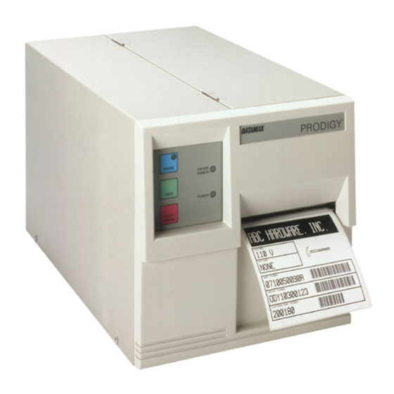
Product Description The Prodigy Label Printer, hereafter referred to as 'the Printer' is a high- performance, low-cost thermal and thermal transfer label Printer. Powerful capabilities and easy to use features set a new price/ performance standard for industrial direct thermal and thermal transfer label printers. - Page 10 10 mil by 15 mil. An optional 152 dot per inch (6 dot/mm) printhead (Prodigy 152) is also available. It is approximately 25% less dense, yet can print 100% UPC/EAN and 9.6 cpi Code 39.
- Page 11 Applications The Printer is designed for use in many different types of applications. Examples include: *Point of sale *Warehouse ticketing *Parts count labeling *Inventory control labeling *Retail merchandise labeling *Pharmaceutical labels *Deli labeling *Retail garment *VICS standard labels *Price marking *HIBC (Health Industry) *Military LOGMARS *UPC shipping container labels...
- Page 12 Features Additional features of the Printer include: Thermal transfer and direct thermal printing Extremely high dot density (203 dots/inch, 8 dots/mm); optional 152 dots/inch, (6 dots/mm) Prints up to 4.0" (101 mm)/sec Large maximum media size: 4.65"W x 99.99"L (118 mm x 2539 mm) Print area of 4.4"W x 99.99"L (112 mm x 2539 mm);...
- Page 13 DATAMAX Corporation certifies that the Prodigy label Printer complies with the RFI suppression requirement of Vfg 1046/1984 for VDE Class B equipment. TUV-GS: The Prodigy Printer has been tested and complies with EN 60 950/06.88 and bears the TUV-GS mark. License Number: S9371819. ________________________________________________________...
-
Page 14: Specifications
Prodigy 152: has nine alphanumeric fonts from .047"H (1 mm) to 10.24"H (260 mm). Character Density: Prodigy: 33.83 cpi FONT 0 at 1X, .70 cpi FONT 6 at 8X Prodigy 152: 25.64 cpi FONT 0 at 1X, .54 cpi FONT 6 at 8X... - Page 15 LOGMARS, HIBC, and AIAG Bar Code Density: Prodigy: 12.69 cpi, Code 3 of 9, 0.005" narrow bar, 3:1 ratio 6.34 cpi, Code 3 of 9, 0.010" narrow bar, 3:1 ratio Prodigy 152: 9.6 cpi, Code 39, 0.0066"...
-
Page 16: Indicators And Switches
Label Material: Thermal transfer-plain coated papers, vinyl, Mylar, metalized paper, nonwoven fabric, fine woven fabric, thermal-visible light scannable paper, infrared scannable paper, thermal ticket/tag stock, thermally sensitive plastic stock Thermal Transfer Ribbon: Black or colored inks; 360 meters long, 4.6 microns, backcoated, ±10% label width Indicators and Switches Indicator Lights:... - Page 17 Electrical Input Voltage: 115 VAC ±10%, single phase 50/60 Hz 230 VAC ±10%, single phase 50/60 Hz Circuit Protection: At 115V = 1.5A Slo Blo; At 230V = circuit breaker at 1.2A Grounding: Unit must be connected to a properly grounded receptacle Environmental Temperature:...
-
Page 18: Printer Options
1.2 Printer Options The Printer hosts a number of different options that can be added to the Printer for additional versatility. These options are described below. CRT Terminal A CRT terminal interface is available for configuring the Printer as a stand-alone label definition and batch label printing system. -
Page 19: Supplies
Present Sensor The Printer can be configured for a “one up” printing mode. With the sensor installed and enabled, the Printer will not print the next label in its internal buffer(s) until the last label printed has been removed from the Printer. - Page 20 Common direct thermal stocks include visible-light scannable paper, infrared scannable paper, thermal ticket, tag, and sensitive plastic stocks. A similar list of thermal transfer stocks includes plain coated vinyl, Mylar, metalized paper, and nonwoven and fine woven fabrics. Consider three important factors when selecting direct thermal media: The abrasive qualities of the material that covers the thermal reactive layer of the paper.
- Page 21 Thermal Transfer Ribbons Use of ribbons other than those supplied or approved by the manufacture's Value Added Resellers (VARs) or by the manufacture may result in a poor quality printing of bar codes and their ability to be scanned and /or may invalidate the printhead warranty. The manufacture's ribbons are: Black ink, scratch, and smudge resistant 1182 feet long (360 meters), 4.6 microns thick...
- Page 22 Label/Tag Media Specifications Description MAX(in.) MIN(in.) Label width 4.650 0.750 Backing width 4.650 0.750 Gap between labels 99.99 0.100 Label length 99.99 0.500 Backing thickness 0.010 0.0023 Label thickness 0.010 0.0023 Width of sensor opening 0.500 0.200 Distance from edge of media 2.250 0.200 to edge of sensor opening...
-
Page 23: Getting Started
Getting Started 2.1 Unpacking and Inspection Inspect the shipping container(s) for signs of being dropped, crushed or punctured. If damage is evident, contact the carrier directly to specify the nature and extent of the damage. The Printer is packed in custom styrofoam packaging. The Printer itself is enclosed in a plastic bag to reduce the chance of moisture damage during shipping. -
Page 24: Equipment Checklist
2.2 Equipment Checklist In addition to the Printer, the shipping container(s) should include the following standard items: Printer's Operators Manual Front door panel (packaged separately) 20 fan-folded labels Thermal transfer ribbon rewind clamp Back rewind/label rewind clamp Power cord Additionally, items purchased separately may be included. These items might include: Additional labels Additional ribbons... -
Page 25: Switches And Indicators
2.3 Switches and Indicators The Printer has 3 function buttons, 3 indicator lights, 3 switches including a 8 position DIP switch on the back of the Printer, and a Darkness potentiometer for print quality control. These buttons, switches and indicators are shown in figures 2-1 and 2-2, with descriptions for each in the section that follows. - Page 26 Figure 2-2 Rear View PAUSE Button-- The PAUSE Button, when pressed, causes the Printer to temporarily stop the printing of labels after the current label is printed. All data is still held in memory. The Printer can resume printing by pressing the PAUSE Button a second time.
- Page 27 STOP/CANCEL The STOP/CANCEL Button, when Button-- pressed, stops and cancels the current run of labels. The Printer will then begin to print the next (if any) batch of labels stored in the print buffer. PAUSE Indicator The PAUSE Indicator Lamp will light when Lamp-- the PAUSE Button is pressed, the lamp will go out when the button is pressed again.
- Page 28 TRANSFER ON In Thermal Transfer printing, the individual dot Switch-- elements of the printhead apply heat to a ribbon. The “ink” on the ribbon is a specially formulated material that is literally melted into the print media, bonding with the media to produce an image.
-
Page 29: Setup And Self Test
Setup and Self Test The Printer has a unique SETUP AND SELF TEST routine that should be run after unpacking and physical inspection to ensure the Printer was not damaged during shipment. The self test will save time and familiarize you with the Printer's function that can be set, such as temperature, print speed, and slew rate. -
Page 30: Installing Print Media
The Printer is also manufactured for 230 VAC operation. Most of these Printers are shipped to international markets. If you are at all uncertain about the configuration of the Printer, or the outlet you are connecting to, check with a qualified service technician to verify the installation before connecting power. - Page 31 3. Disengage the printhead by rotating the Head Lift Lever clockwise to the UP position. 4. Loosen the Label Adjust Guide and slide it outward. 5. Insert the label media as shown. Figure 3-2 Media Routing 6. Slide the Label Adjust Guide inward until it just touches the media, tighten the guide in place.
- Page 32 NOTE: Insure the TRANSFER switch is in the OFF position if a thermal transfer ribbon is not installed. If this is not done the Printer will only feed about .25" of media each time the FEED button is pushed. Media Rewind Instructions 1.
- Page 33 3. Route the media so that it passes over the Rewind Adapter as shown in Figure 3.4. 4. Route the end of the media around the Media Rewinder and replace the Clasp to hold it in place. Figure 3-4 Routing Media for Rewinding ________________________________________________________ Setup and Self Test Page - 25...
- Page 34 Ribbon Loading Instructions 1. Disengage the Printhead by rotating the Head Lift Lever clockwise to the UP position. 2. Slide the ribbon spool onto the Ribbon Supply Hub. 3. Route the ribbon and replace the clasp over the ribbon as shown in Figure 3.5.
-
Page 35: Power Up Self Test
Alternate Ribbon Loading Instructions When loading partial ribbons, or ribbons with leaders that have a high elasticity, you may have some difficulty removing the clasp after the ribbon has been consumed. As an alternate method of loading the ribbon, you can neatly wrap the ribbon over a 1.3" paper ribbon core, turning the take up spindle until the ribbon appears to track smoothly through the Printer. -
Page 36: Explanation Of The Self Test Label
3.4 Explanation of the Self Test Label Below is an illustration of an actual Configuration Label. The label contains information of the Printer's current setup settings, as well as the RAM and ROM checksums, and other important information. PROGRAM VERSION: 02.4 10/22/90 SYSTEM ROM CHECKSUM:... - Page 37 SYSTEM ROM CHECKSUM: SYSTEM ROM CHECKSUM: GOOD GOOD FONT FONT ROM CHECKSUM: ROM CHECKSUM: GOOD GOOD TOTAL TOTAL ROM SUM: ROM SUM: GOOD GOOD SYSTEM RAM-U15 CHECKS GOOD SYSTEM RAM-U15 CHECKS GOOD SYSTEM RAM-U16 CHECKS GOOD SYSTEM RAM-U16 CHECKS GOOD SYSTEM RAM-U17 CHECKS GOOD SYSTEM RAM-U17 CHECKS GOOD These lines list the results and values of all RAM and ROM...
-
Page 38: Print Test Label
Print Test Label The Print Test Label consists of a test pattern of printed bars, this label can be used to isolate problems in print quality and to determine bad printheads or rollers. Figure 3-7 Print Test Label ________________________________________________________ Page - 30 Setup and Self Test... - Page 39 If you want to perform the TXD/RXD and CTS/DTR loop checks, you will need to fabricate a test plug as illustrated below in Figure 3.8 Connect the plug to the RS-232 connector on the back of the Printer and run the self test again. Figure 3-8 Test Plugs If the Printer passes the loop back checks the following two line will print on the Self Test label.
-
Page 40: Monitoring Input After Self Test
3.6 Monitoring Input After Self Test After the self test is complete, the Printer goes into a mode that is very useful in two major situations. The first situation involves checking serial transmissions from the sending device to the Printer. The second situation involves monitoring data that is to be interpreted as graphic control statements. -
Page 41: Printhead Pressure And Support Adjustment
3.7 Printhead Pressure and Support Adjustment The Printers printhead pressure is not adjustable. Two springs in the head mount assembly apply a fixed 9.5 lbs of force upon the printhead. The adjustment of the Printhead Support may be required if you are changing from wide full width media to narrow media that is significantly different in terms of thickness. - Page 42 Figure 3-9 Printhead Adjustment NOTE: The mount screws which secure the head support plate also secure the ribbon shield. When loosening these screws, be aware that both the plate and the shield are adjustable. If you move one, the other may move also. NOTE: For narrow stock the head support plate should be adjusted so that the print image on the outside edge of...
-
Page 43: Modes Of Operation
3.8 Modes of Operation Before operating the Printer, the correct mode of operation must be selected. Standard input and stand-alone batch labeling are the two different modes of operation available. Standard Input In this mode, the Printer receives ASCII data from the RS-232C/RS-422 serial data input port and prints characters on label media as requested by graphic control statements that the host device generates. -
Page 44: Selecting The Mode
3.9 Selecting the Mode After the mode of operation is determined, the function switch on the back of the Printer can be changed to select the desired mode. Turn the Printer OFF while making changes to the switch settings (function switches are only read during power-up). -
Page 45: Setting The Baud Rate And Word Length
3.11 Setting the Baud Rate and Word Length For all modes of operation, you must set the baud rate of the interface. On the back of the Printer, you will find a single eight-position DIP switch. Positions 1, 2, and 3 control the setting of the baud rate. The following table gives the position of the three switches and the corresponding baud rate that can be obtained by each setting: S1-1... -
Page 46: Using The Present Sensor Option
3.12 Using the Present Sensor Option With the addition of the PRESENT SENSOR option, the Printer can be configured for “one up” printing mode. With the sensor installed and enabled, the Printer will not print the next label in its internal buffer(s) until the last label printed has been removed from the Printer. -
Page 47: Maintenance
3.13 Maintenance Very little Printer maintenance is required. Keeping the Printer clean will help insure trouble free operation. Points of interest include: 3.13.1 Printhead WARNING: Turn OFF the Printer and unplug the unit from the outlet before cleaning the printhead. The Printhead can become dirty from operation. - Page 48 3.13.2 Internal/External Cleaning WARNING: Turn OFF the Printer and unplug the unit from the outlet before cleaning any part on the Printer. A periodical cleaning should be done on all rollers, guides and assemblies. Isopropyl Alcohol can be used to clean these areas. This will insure all items are free from residue and will not contribute to any Printer malfunctions.
-
Page 49: Using The Printer
Using the Printer 4.1 Printer Command Interpreter After the cable is connected and the baud rate of the interface is selected, you are ready to start formatting labels. Typical line printers require little, if any, formatting of data to trigger printing. - Page 50 The Printer handles the printing of graphics in a manner that requires less system overhead by the host device. All of the dot patterns for nine different human readable fonts, and formulas for creating different types of bar codes are built directly into the Printer. All of these fonts and bar codes are presented in several different magnifications in APPENDIX D.
-
Page 51: Control Code Reference
4.2 Control Code Reference The commands that are executed by the host device fall into two basic categories: SYSTEM and LABEL FORMATTING commands. SYSTEM commands control such functions as test pattern, setting and clearing the front panel switches, and interactive communications to a host device. -
Page 52: System Level Commands - Immediate
4.3 System Level Commands — Immediate These commands are interpreted before entry into the buffer; therefore, they happen immediately. Upper level commands invoked after the attention getter: $01 (^A). COMMAN DESCRIPTION Reset command, executes a power-on reset. Can be used as an operation cancel. Clears buffers and initializes memory. -
Page 53: System Level Commands
(continued) COMMAN DESCRIPTION Send Printer status (1 byte Hex). Printer sends a single byte in which each bit represents one of the Printer’s status flags. Bit # Description Command interpreter Busy ? Paper out ? Ribbon out ? Only when enabled Printing batch ? Busy printing ? Printer paused ? - Page 54 ________________________________________________________ Page - 46 Using the Printer...
- Page 55 4.4 System Level Commands (continued) COMMAN DESCRIPTION cnnnn Set Continuous Paper Length. (For continuous forms applications) nnnn = length of paper to feed per label format. Set to zero for normal operation. Dbaaaa Memory dump (TEST MODE COMMAND). = Bank address. aaaa = 4-digit address.
- Page 56 Request memory module status Response from Printer x-bt<cr> x=Y or N for bank checksum status b=Bank partition being reported t =G for graphics bank L for label format bank X for unformatted bank ________________________________________________________ Page - 48 Using the Printer...
- Page 57 4.4 System Level Commands (continued) COMMAND DESCRIPTION Kbaaaa Change memory (TEST MODE COMMAND). b = Bank address. aaaa = 4-digit address. ENTER LABEL FORMATTING COMMAND input mode. After entering LABEL FORMATTING mode, the Printer expects FIELD RECORD definition and LABEL FORMATTING commands until command “E”...
-
Page 58: Label Formatting Commands
4.4 System Level Commands (continued) COMMAND DESCRIPTION Print dot pattern test label. Unnss.., Format register fill. nn = String # in format, must be 2 digits. ss = New string data followed by a <CR>. Must equal original string length. Set pseudo switch settings. - Page 59 4.5 Label Formatting Commands (continued) COMMAND DESCRIPTION Enter last field’s string into global table. Strings are consecutively named within a label format starting with A. Up to P strings may be stored into global table. Enter heat setting for label. nn = 2 digits.
- Page 60 4.5 Label Formatting Commands (continued) COMMAND DESCRIPTION Set to format label before printing. Will cause Printer to format 560 dot rows into bit mapped RAM before the first dot row is plotted to media. Terminate field generation and exit to command processor.
-
Page 61: Field Definition - Human Readable Fields
4.6 Field Definition — Human Readable Fields Field definition statements to be sent after “STX L” SYSTEM LEVEL command. LABEL FORMATTING mode terminated by “E” or “X” LABEL FORMATTING command. Field Record for Label Input Mode Human Readable Fields: CHAR # DESCRIPTION Flag for rotation. -
Page 62: Field Definition - Bar Code Fields
4.7 Field Definition — Bar Code Fields Field definition statements to be sent after “STX L” SYSTEM LEVEL command. LABEL FORMATTING mode terminated by “E” or “X” LABEL FORMATTING command. Field Record for Label Input Mode Bar Code Fields: CHAR # DESCRIPTION Flag for rotation. -
Page 63: Graphic Images
12, 13, 14, 15 Column address. Must be 4 digits (0.01" step) 0000-0447 16,... String data. ASCII printable data for font selected. Terminate with a <CR>. ^B Switch to string input commands: Select stored string from global table. n = String location. A-P. 4.8 Graphic Images To enter the graphic image input routine, the Printer must be outside of the LABEL INPUT command interpreter. - Page 64 The following example creates and prints the image DATAMAX using the type “F” graphics formatting method. The character “^B” denotes the ASCII STX character.
- Page 65 ^BqA(CR) ^BIAAFLOGO(CR) 8030FFFFFFFFFFFFFFFFFFFFFFFFFFFFFFFFFFFFFFFFFFFFFFFFFFFFFFFFFFFFFFFFFFFFFFFFFFFFFFFFFFFFFFFFFFFF0000(CR) 8030FFFFFFFFFFFFFFFFFFFFFFFFFFFFFFFFFFFFFFFFFFFFFFFFFFFFFFFFFFFFFFFFFFFFFFFFFFFFFFFFFFFFFFFFFFFF0000(CR) 8030FFFFFFFFFFFFFFFFFFFFFFFFFFFFFFFFFFFFFFFFFFFFFFFFFFFFFFFFFFFFFFFFFFFFFFFFFFFFFFFFFFFFFFFFFFFF0000(CR) 8030FFFFFFFFFFFFFFFFFFFFFFFFFFFFFFFFFFFFFFFFFFFFFFFFFFFFFFFFFFFFFFFFFFFFFFFFFFFFFFFFFFFFFFFFFFFF0000(CR) 8030FFFFFFFFFFFFFFFFFFFFFFFFFFFFFFFFFFFFFFFFFFFFFFFFFFFFFFFFFFFFFFFFFFFFFFFFFFFFFFFFFFFFFFFFFFFF0000(CR) 8030FFFFFFFFFFFFFFFFFFFFFFFFFFFFFFFFFFFFFFFFFFFFFFFFFFFFFFFFFFFFFFFFFFFFFFFFFFFFFFFFFFFFFFFFFFFF0000(CR) 8030FFFFFFFFFFFFFFFFFFFFFFFFFFFFFFFFFFFFFFFFFFFFFFFFFFFFFFFFFFFFFFFFFFFFFFFFFFFFFFFFFFFFFFFFFFFF0000(CR) 8030FFC00000007FFC0003FFFFC001FC0001FC0003FFFFC0018000FFC001FF8000C0003FFFFE000000FFFFE0001FFFFF0000(CR) 8030FFC00000000FFC0003FFFFC001FC0001FC0003FFFFC0018000FFC001FF800040001FFFFE0000007FFFC0001FFFFF0000(CR) 8030FFC000000003FC0001FFFFC001FC0001FC0001FFFFC0018000FFC001FF800040001FFFFE0000003FFFC0001FFFFF0000(CR) 8030FFC000000000FC0001FFFFC001FE0001FE0001FFFFC00180007FC000FF800060001FFFFE0000003FFFC0003FFFFF0000(CR) 8030FFE0000000007E0001FFFFC001FE0001FE0001FFFFC00180007FC000FFC00060000FFFFE0000001FFFC0003FFFFF0000(CR) 8030FFE0000000003E0000FFFFC001FE0000FE0000FFFFC00180007FC0007FC00020000FFFFE0000001FFF80003FFFFF0000(CR) 8030FFE0000000001E0000FFFFC001FE0000FF0000FFFFC001C0007FC0007FC00030000FFFFE0010000FFF80003FFFFF0000(CR) 8030FFE0000000000F0000FFFFC001FE0000FF0000FFFFC001C0007FC0007FC00030000FFFFE00180007FF80007FFFFF0000(CR) 8030FFE0000000000700007FFFC001FF0000FF80007FFFC001C0007FC0003FC000380007FFFE00180007FF80007FFFFF0000(CR) 8030FFF0000000000380007FFFC001FF0000FF80007FFFC001C0003FC0003FE000380007FFFE001C0003FF80007FFFFF0000(CR) 8030FFF0000000000380007FFFC001FF0000FF80007FFFC001C0003FC0003FE000380007FFFE001E0003FF80007FFFFF0000(CR) 8030FFF0000000000180003FFFC001FF00007FC0003FFFC001C0003FC0001FE0001C0003FFFE001E0001FF0000FFFFFF0000(CR) 8030FFF00000000001C0003FFFC001FF00007FC0003FFFC001E0003FC0001FE0001C0003FFFE001F0000FF0000FFFFFF0000(CR) 8030FFF00007C00000C0003FFFC001FF00007FE0003FFFC001E0003FC0000FF0001E0003FFFE001F0000FF0000FFFFFF0000(CR) 8030FFF80007F80000E0001FFFC001FF80007FE0001FFFC001E0003FC0000FF0001E0001FFFE001F80007F0000FFFFFF0000(CR) 8030FFF80007FC0000E00000000001FF80007FE00000000001E0001FC0000FF0001E00000000001FC0007F0000FFFFFF0000(CR) 8030FFF80007FE0000600000000001FF80003FF00000000001E0001FC00007F0000F00000000001FC0003F0001FFFFFF0000(CR) 8030FFF80003FF0000700000000001FF80003FF00000000001F0001FC00007F0000F00000000001FE0001E0001FFFFFF0000(CR) 8030FFF80003FF0000700000000001FF80003FF00000000001F0001FC00007F8000F00000000001FE0001E0001FFFFFF0000(CR) 8030FFFC0001FFC0003C0000000001FFE0001FFE0000000001F8000FC00000FC0007E0000000001FFE00000003FFFFFF0000(CR) 8030FFFE0001FFC0001E0000000001FFE0001FFE0000000001F8000FC00000FC0007E0000000001FFF00000003FFFFFF0000(CR) 8030FFFE0001FFC0001E0000000001FFE0001FFE0000000001F8000FC00000FC0007F0000000001FFF00000007FFFFFF0000(CR) 8030FFFE0000FFC0001F0000000001FFE0000FFF0000000001F8000FC000007C0003F0000000001FFF80000007FFFFFF0000(CR) 8030FFFE0000FFC0001F0000000001FFE0000FFF0000000001FC0007C000007E0003F0000000001FFF80000007FFFFFF0000(CR) 8030FFFE0000FFE0001F0001FFC001FFE0000FFF8001FFC001FC0007C000003E0003F8000FFE001FFFC0000007FFFFFF0000(CR) 8030FFFE0000FFE0000F8001FFC001FFF0000FFF8000FFC001FC0007C000003E0003F8000FFE001FFFE000000FFFFFFF0000(CR) 8030FFFF0000FFE0000F8000FFC001FFF0000FFF8000FFC001FC0007C000003E0003F8000FFE001FFFE000000FFFFFFF0000(CR) 8030FFFF0000FFE0000F8000FFC001FFF00007FFC000FFC001FC0007C000001F0001FC000FFE001FFFF000000FFFFFFF0000(CR) 8030FFFF00007FE0000FC000FFC001FFF00007FFC0007FC001FE0007C002001F0001FC0007FE001FFFF000000FFFFFFF0000(CR) 8030FFFF00007FF0000FC0007FC001FFF00007FFE0007FC001FE0003C002001F0001FE0007FE001FFFF800000FFFFFFF0000(CR) 8030FFFF00007FF0000FE0007FC001FFF80007FFE0007FC001FE0003C003000F0001FE0007FE001FFFFC00001FFFFFFF0000(CR) 8030FFFF80007FF00007E0007FC001FFF80007FFE0003FC001FE0003C003000F0001FE0003FE001FFFFC00001FFFFFFF0000(CR) 8030FFFF80007FF00007E0003FC001FFF80003FFF0003FC001FE0003C00300078001FF0003FE001FFFFE00001FFFFFFF0000(CR) 8030FFFF80003FF00007F0003FC001FFF80003FFF0003FC001FE0003C00380078000FF0003FE001FFFFE00001FFFFFFF0000(CR)
-
Page 66: Printing Lines And Boxes
4.9 Printing Lines and Boxes Lines and boxes can be created by requesting font “X” from within the LABEL COMMAND interpreter. The horizontal and vertical multipliers work with the line and box routines in the same manner as human readable fonts. The format of the data area is as follows: Lhhhvvv Where L = L to specify line drawing (solid box) - Page 67 2. The Printer begins to look for strings terminated by ASCII CRs (DEC 13, HEX 0D). The interpreter takes the data in the string and places the appropriate pieces into the appropriate registers. Whenever the Printer encounters an ASCII control code that has a value of less than 32, the data is not accepted.
- Page 68 THE PRINTER IS HERE 123456 ROTATION 1 HOME POSITION FIGURE 4-2 4. After the rotation field, the next character received is the font type. It must be one of the characters 0 through 8 to select a human readable font or A through L to select a bar code font. Uppercase bar code fonts will print with human readable interpretation, lowercase bar code fonts do not include the interpretation.
- Page 69 If the font selected is a bar code, this character specifies the wide bar width. The range of allowable values for bar code fonts is 1 to 9 and A through K. This range will give a wide bar width of 0.005" to 0.300"...
- Page 70 8. The next four digits, bytes 8 through 11, are the vertical offset. This offset determines the placement, from the home position, of the data that is specified at the end of the string received. The home position is the lower left hand corner of the next print media currently held under the printhead.
- Page 71 12. After the last field is sent, the host device terminates the formatting session by sending an ASCII “E” (DEC 69, HEX 45) as a single character string terminated by an ASCII CR (DEC 13, HEX 0D). The label Printer will print the label from the field registers created and return to the SYSTEM command processor.
-
Page 72: Register Loading
The first string “132100001000050TEST 123” is defined as the register number “01” in the Printer. On the label, it appears as the human readable message “TEST 123” located above the bar code. You can see from the sample label that the data printed in the standard left-to-right rotation “1”, in font “3”, at a 2X width and 1X height magnification. - Page 73 The ASCII character STX G is sent to instruct the Printer to print a label from its internal register data. After the label has finished printing, the host device may send additional STX G characters to print additional copies of the same label. The host device may also reload a particular register with new data and send another STX G command.
-
Page 74: Label Formatting Commands
4.12 Label Formatting Commands There are several commands listed in the label formatting tables in Section 4.5 that have not been covered in the examples. This section examines these commands. The following commands are sent to the Printer after the STX L command, which causes the Printer to switch from the SYSTEM level command processor to the LABEL FORMATTING command processor. - Page 75 The control on the front of the Printer labeled “DARKER” —>” is for matching replacement printheads to the Printer during the head replacement procedure. It has very little control over the actual burn temperature used for imaging. This command is beneficial when the Printer is used with several different media types.
- Page 76 4. “Pa” COMMAND. SETTING THE PRINT SPEED. The print speed of the Printer can be adjusted by the host device to meet specific requirements of particular applications. The command “Pa” will set the print speed according to the single digit represented by the “a”...
- Page 77 7. “+pii...” COMMAND. THE INCREMENT FUNCTION. The Printer formatter is capable of incrementing data fields between each print. To cause a field to increment, send the field in the normal manner to the Printer. After the ASCII CR that terminates the field, send the string “+pii...”...
- Page 78 The “-” character may be replaced by a “<” character to make the field decrement alphanumerically instead of just numerically. To generate a single field label format that prints the first label with a value of 10000 and decrements by 1 for three labels, refer to the following commands: 000 0000 0000 10000 CR -01 CR...
-
Page 79: System And Formatting Commands
10. PLACE DATA IN GLOBAL REGISTER The Printer also contains a utility for printing duplicate data fields (for example, several different places on a label). After a field has been created, the “G” command may be sent as the next string to the Printer. - Page 80 1. “SOH A” COMMAND. CHECKING THE PRINTER STATUS. The Printer can be polled as to the current Printer status. The SYSTEM command to cause the Printer to send this data is “SOH The Printer will respond as soon as it is able to with an 8-character response followed by an ASCII CR (DEC 13, HEX 0D).
- Page 81 4. “STX Vn” COMMAND. SETTING THE PSEUDO SWITCHES. Switch SW1, mounted on the back of the Printer, is read on power- up or on soft reset. The positions of switches 5 through 8 can be modified through this command. Send “STX Vn” where “n” is a hex value of 0 to F to define the settings.
-
Page 82: Controlling Print Quality
6. “O####” COMMAND. CHANGING THE DEFAULT LABEL OFFSET. The “O####” command changes the label offset. The Printer will accept the “####” string to be in the range of 0000 to 0999. The Printer normally stops the label media at 0.20" past the printhead. This means that the last label printed is still attached to the label backing and can be removed by an operator. - Page 83 You will find that printing fine images on the less expensive direct thermal and thermal transfer media at the higher speeds can be tricky. At one heat setting the image will fade and at the next higher heat setting the image can bleed. This is because the reaction temperature of the media is so high that at higher rates of speed, it cannot react quick enough.
- Page 84 ________________________________________________________ Page - 76 Using the Printer...
-
Page 85: Using The Printer's Internal Labeling Software
Using the Printer's Internal Labeling Software The program is very easy to learn and operate. Just two screens are used to create or modify and then print labels. A system maintenance screen is included for printing test labels, copying and formatting memory modules, and several other functions. -
Page 86: Connect Cables
5.1.1 Connect Cables Verify that the LINK CRT and the Printer main power switches are OFF. Connect the LINK CRT terminal to the Printer with the supplied cable, or construct an MXM-type cable as described in APPENDIX C. Plug in the supplied power cords for the Printer and the LINK CRT terminal. -
Page 87: Select Stand-Alone Labeling Software Mode
Handshake: NONE Mode: Data Bits: Stop Bits: Parity: NONE Baud Rate: 9600 Keys: Blk End: US/CR Auto NL: Compatible: LINK MC 2 Function keys equivalent to: CNTL W CNTL X CNTL Y CNTL Z 5.1.3 Select Stand-Alone Labeling Software Mode The Printer is typically shipped in the RS-232 mode for use with PCs. -
Page 88: Verify Setup, Power Up, And Load Media
5.1.4 Verify Setup, Power Up, and Load Media Check that all connections are made and that you have correctly configured DIP switch SW-1. Turn on the CRT first and then the Printer's power switch. Press the F1 key on the CRT several times. The CREATE/MODIFY LABEL and PRINT LABEL screens should toggle back and forth. - Page 89 4. Press and hold the ALT key and press the “S” key at the same time. This screen will appear: SYSTEM MAINTENANCE 1) FORMAT MODULE 2) COPY MODULE 3) METRIC? NO 4) PRINT TEST LABEL 5) SYSTEM TEST LABEL 6) TEST MODULE 7) RESET PRINTER 8) EXIT TO RS232 SYSTEM ENTER NUMBER:...
- Page 90 6. Now you need to decide how to partition the module’s memory. The memory module can be configured into two single 16K banks or joined together into one continuous bank. The two banks are referred to as bank A and bank B. For most applications involving the internal batch program, you should format the module so that bank A and B are both formatted to accept label formats.
-
Page 91: Function Keys
5.2 Function Keys Four function keys are used extensively in the label formatting process. They are labeled F1, F2, F3, and F4. These keys have the following functions: F1 or ESC (SWITCH) Toggles between the PRINT and CREATE/MODIFY LABEL screens. F1 can only be used in the LABEL NAME: position of the CREATE/MODIFY or PRINT screens. -
Page 92: Alt Keys
5.2.1 ALT Keys Several very important and powerful Printer settings are called up and/or controlled by the ALT key. To use the ALT functions, press and hold the ALT key as you press another key. The ALT functions are: ALT-P While in the far left position (ROT) of the CREATE/MODIFY LABEL screen or the SAMPLE? position of the PRINT LABEL screen, press ALT-P to bring up the PRINT PARAMETERS window. - Page 93 Valid settings, defaults, and a description of each print parameter are listed below: HEAT FACTOR: 0 to 20. Default is 10. PRINT RATE: A to G. A = 1 inch/sec. G = 4 inches/sec. Default is E (3.0 inches/sec.). SLEW RATE: A to G.
- Page 94 If ALT-P parameters are changed while in the CREATE/MODIFY LABEL screen, the changes are saved with the label format. If they are changed in the PRINT LABEL screen, they are not saved and will affect only the current print job. Changing parameters in the PRINT LABEL screen is useful when testing a new label to determine optimum print parameter settings for that particular format.
-
Page 95: Other Important Keys
5.3 Other Important Keys Several other keys are used in the editing and printing steps. These keys have the following functions: RETURN Enters an answer for the prompt and moves to the next position if the answer is acceptable. ARROW KEYS Used to move left and right and up and down in the CREATE/MODIFY and PRINT screens. - Page 96 PRINT LABEL LABEL NAME: QUANTITY:0 Press the F1 key, and the screen will look like this: CREATE/MODIFY LABEL DIRECTORY: MEMORY LEFT:99% LABEL NAME:----------------------- ROT FNT XW XH BH ROW COL TYPE DATA/PROMPT --- --- -- -- -- --- --- ---- ----------- 2.
- Page 97 3. Enter up to a 16-character alphanumeric name for this label, followed by the RETURN key. The message “NEW LABEL FORMAT?” appears. Answer “Y” for yes or “N” for no. If yes, the operation moves to the ROT position. If the cursor won’t proceed past the “NEW LABEL FORMAT”...
- Page 98 The “X” font selects box and line drawing. Later, in the DATA/PROMPT field, you will enter the following format for lines or boxes: LINES: Lhhhvvv Where: L = “L” specifies line drawing hhh = horizontal width of line vvv = vertical height of line NOTE: Reverse printing is accomplished by printing a very high (or wide) solid line.
- Page 99 6. The XW and XH positions are used to magnify widths and heights of fonts and to change the X/Y ratio of bar codes. a. If a font, valid responses are 1, 2, 4, and 8. Default is 1 for fonts.
- Page 100 Enter up to a 4-digit number for the desired vertical placement of your field, followed by the RETURN key. If the measurement you have entered is acceptable, the prompt moves to the COL position. If the measurement you select is too large for the given space or the capability of the Printer, the following error message will appear: NUMBER OUT OF RANGE You will have to re-enter the data.
- Page 101 11. The TYPE position tells the Printer how the DATA/PROMPT area is to be used. You have eight choices: C, D, P, R, +, -, <, and >. a. The most common TYPE is “D” for data. It tells the Printer that fixed data will be entered in this field.
- Page 102 If any of the above are entered, you will be printing either incrementing or decrementing numbers or letters in the label position you specified earlier in this field. Information you add in the DATA/PROMPT field in the next step will tell the Printer by what increment you want to count.
- Page 103 Use the DEL or HOME key or the arrow keys to change any information. Also, if the Printer does not allow you to enter as many characters as you need, you may have to back up with the arrow keys to allow more room on the label or change font size. For special font “X”, enter the required information.
-
Page 104: Print Label Screen
d. For comment fields, enter the data you wish to have appear on the PRINT screen in the DATA/PROMPT field. e. Repeat Fields. Enter the data in the DATA/PROMPT field just as if the field were a type “D” field. Place a “^” character in the data string at the place you wish to insert the data from the previous field into this field. - Page 105 When on the PRINT LABEL screen, the procedure for printing a label is as follows: 1. Enter the LABEL NAME you want to print and press the RETURN key. The prompt moves to the QUANTITY position. (If for some reason the Printer does not find the label name you entered, you will receive an error message and will have to re-enter the label name.) The F2 key (LIST) is available when in the LABEL NAME position to list all names entered in the currently installed memory module.
-
Page 106: System Maintenance Screen
5.6 System Maintenance Screen The third screen, SYSTEM MAINTENANCE, is used to format and copy memory modules, print test labels, and perform several other maintenance functions. Access the screen in the LABEL NAME position of the CREATE/MODIFY LABEL or PRINT LABEL screens by keying in ALT-S. - Page 107 4. PRINT TEST LABEL. Prints a head test label. Used as a relative gauge of head condition and wear. 5. SYSTEM TEST LABEL. Lists all current Printer settings and checks both ROM and RAM. Prints a head test label after the system test. 6.
- Page 108 ________________________________________________________ Page - 100 Using the Printer's Internal Labeling Software...
-
Page 109: Appendix Aascii Control Code Chart
Appendix A ASCII Control Code Chart Char Hex Char Dec Hex Char Hex Char Dec Hex Ctrl @ Ctrl A Ctrl B Ò Ctrl C Ctrl D 100 64 Ctrl E 101 65 Ctrl F & 102 66 Ctrl G Ô... - Page 110 Char Char Char Char Ç á Ó ü í ß é ó Ô â ú Ò ä ñ õ à Ñ Õ å ª ã µ ç ° Ã þ ê ¿ Þ ë ® Ú è Û ï Ù î...
-
Page 111: Dip Switch Settings
Appendix B DIP Switch Settings S1 FUNCTION SELECTION S1-1 S1-2 S1-3 9600 4800 2400 1200 19200 TEST/9600 WORD LENGTH S1-4 8,1,N-BIT WORD 7,2,N-BIT WORD MODE SELECTION S1-5 STANDARD RS-232/RS-422 INPUT INTERNAL BATCH LABELING PRESENT SENSOR S1-6 DISABLE SENSOR ENABLE SENSOR ________________________________________________________ Appendix B Page B-1... - Page 112 RIBBON SENSOR S1-7 STANDARD SENSING INVERTED SENSING (Colored and Special Ribbons) CUTTER ENABLE S1-8 REMOTE CUT ENABLED REMOTE CUT DISABLED ________________________________________________________ Page B-2 Appendix B...
-
Page 113: Interface Cable Applications
Appendix C Interface Cable Applications Part Description Number 556000 Printer to CRT Terminal (DB25P) RS-232 556001 Printer to PC 9 Pin (DB9S) RS-232 556002 Printer to PC 25 Pin (DB25S) RS-232 899516 Printer to PC Parallel Port (DB25P) Pin Connections All unlisted pins are not connected. -
Page 114: Null Modem Cable
Null Modem Cable HOST Printer NOTE: Cable is used for typical connection to other DCE equipment with XON/XOFF flow control. Straight Cable (MM) HOST Printer SHIELD RXD 2 2 TXD TXD 3 3 RXD GROUND DB25P DB25P NOTE: Cable is used for typical connection to other DCE equipment with XON/XOFF flow control. -
Page 115: Pc (Db25P) To Printer
PC (DB25P) to Printer "PC" (DTE) Printer NOTE: Cable is used for connection to “PC” compatible with DB25P communication Ports. Flow control is either XON/XOFF or CTS/DTR. ________________________________________________________ Appendix C Page C-3... -
Page 116: Pc (Db9P) To Printer
PC (DB9P) to Printer "PC" (DCE) Printer NOTE: Cable is used for connection to “PC” compatible with DB25P communication Ports. Flow control is either XON/XOFF or CTS/DTR. ________________________________________________________ Page C-4 Appendix C... -
Page 117: Available Fonts And Bar Codes
Appendix D Available Fonts and Bar Codes All character fonts and bar codes available on the Printer are illustrated on the following pages. Each font and bar code has a “name” associated with it for use in programming. Human readable fonts have been given numeric names while bar code fonts are selected by alpha names. -
Page 118: Bar Codes With Interpretation Line
BAR CODES With Interpretation Line (UPPERCASE) Ratio Based Barcodes 203 DPI Printer (actual dpi - 203) Ratio (i.e. 2:1, 3:1, 5) Narrow Bar Name 0.005 0.005 0.005 0.010 0.010 0.010 A 30F9 15.62 7.00 12.69 7.81 3.50 6.34 D 120F5 14.50 6.34 11.28... - Page 119 Element Based Barcodes 203 DPI Printer (actual dpi - 203) Multiplier = Narrow Bar 0.0049 Width 0.0049 0.0049 0.0049 0.0049 0.0049 B UPC-A 114% 152% 227% 303% C UPC-E 114% 152% 227% 303% E CODE128 9.23 3.69 6.15 4.61 1.85 3.08 F EAN-13 114%...
-
Page 120: Standard Fonts - Human Readable Examples
ALL EXAMPLES ARE PRINTED WITH A 10 x 10 MIL PIXEL SIZE, AND A 1X MAGNIFICATION ON THE HORIZONTAL AND VERTICAL DOT PATTERNS. III. Standard Fonts - Human Readable Examples 0: Identifies a 96-character alphanumeric font. Uppercase and lowercase. Characters are 7 dots high, 5 dots wide, and 1 dot spacing. - Page 121 2: Identifies a 138-character alphanumeric upper and lowercase font. Characters are 18 dots high, 10 dots wide, and 2 dots spacing. 203 DPI Printer 152 DPI Printer 3: Identifies a 62-character alphanumeric font, uppercase. Characters are 27 dots high, 14 dots wide, and 2 dots spacing. 203 DPI Printer 152 DPI Printer Appendix D...
- Page 122 4: Identifies a 62-character alphanumeric font, uppercase. Characters are 36 dots high, 18 dots wide, and 3 dots spacing. 203 DPI Printer 152 DPI Printer Page - D6 Appendix D...
- Page 123 5: Identifies a 62-character alphanumeric font, uppercase. Characters are 52 dots high, 18 dots wide, and 3 dots spacing. 203 DPI Printer 152 DPI Printer Appendix D Page D-7...
- Page 124 6: Identifies a 62-character alphanumeric font, uppercase. Characters are 64 dots high, 32 dots wide, and 4 dots spacing. 203 DPI Printer Page - D8 Appendix D...
- Page 125 6. (Continued) 152 DPI Printer Appendix D Page D-9...
- Page 126 7: Identifies a font that prints OCR-A, size I. Characters are 32 dots high, 15 dots wide, and 5 dots spacing. 203 DPI Printer 152 DPI Printer 8: Identifies a font that prints OCR-B, size III. Characters are 28 dots high, 15 dots wide, and 5 dots spacing. 203 DPI Printer 152 DPI Printer Page - D10...
-
Page 127: Bar Code Examples
IV Bar Code Examples A: Identifies the Code 3 of 9 bar code. Code 39 is an uppercase, alphanumeric bar code that is variable in length. The valid ASCII characters for this font are: 32, 36-37, 42-43, 45-47, 48- 57, 65-90. Code 3 of 9’s normal wide to narrow bar ratio is 3:1. 203 DPI Printer 152 DPI Printer B: Identifies the UPC-A bar code. - Page 128 Option V: Identifies Random Weight UPC bar code. The seventh digit supplied by the host or application software must be an uppercase V followed by 4 digit weight information. Eleven digit checksum is supplied by the Printer. 203 DPI Printer 152 DPI Printer C: Identifies the truncated UPC-E bar code.
- Page 129 D: Identifies the Interleaved 2 of 5 bar code. I 2 of 5 is a numeric- only code. The ASCII range for the numeric codes is 48-57. Code I 2 of 5’s normal wide to narrow bar ratio is 5:2. (Maximum 8 bar codes per label.) 203 DPI Printer 152 DPI Printer...
- Page 130 Code Subset B includes all of the standard upper case alphanumeric keyboard characters plus lower case alphabetic and special characters. To select Code Subset B, precede the data to be encoded with an ASCII B (DEC 66, HEX 42). If no start character is sent for the 128 font, Code Subset B will be selected by default.
- Page 131 Control Codes: Control characters can be encoded into Code Subset A by sending the lowercase ASCII characters “a-z”, “a” = SOH, “b” = STX, “c” = ETX and so on. Font Sizing: Font sizing for 128 on Rotation #2 is not consistent because of the variable character code to character correlation.
- Page 132 F: Identifies the standard EAN-13 bar code. Numeric-only bar code; fixed in length. Twelve digits supplied by host or application software, 13th digit checksum supplied by Printer. If the 13th digit is sent by the host, the Printer will check that character against the calculated checksum and will print the bar code as all zero if they do not match.
- Page 133 G: Identifies the truncated EAN-8 bar code. Numeric-only bar code; fixed in length. Seven digits supplied by host or application software, 8th digit supplied by the Printer. If the 8th digit is sent by the host, the Printer will check that character against the calculated checksum and will print the bar code as all zero if they do not match.
- Page 134 H: Identifies the HIBC (modulo 43 checksum) version of the code 3 of 9 bar code. The checksum will be placed at the end of the data string that is received from the host. The host device must supply the leading “+”s to identify the data format type. Code 39 is an uppercase, alphanumeric bar code that is variable in length.
- Page 135 J: Identifies an I 2 of 5 bar code with modulo 10 checksum calculation. The ASCII range for the numeric codes is 48-57. Code I 2 of 5’s normal wide to narrow bar ratio is 5:2. Font D and L also print different forms of the I 2 of 5 bar code. Maximum 8 bar codes per label.
- Page 136 L: Identifies an I 2 of 5 bar code with modulo 10 checksum (UPC shipping container symbology) that does the special human readable formatting and adds bearer bars to the top and bottom of bars when encoding 13 digits. The ASCII range for the numeric codes is 48-57.
- Page 137 M: Identifies the 2 digit addendum code for UPC fonts. It is a numeric-only bar code with a fixed length of 3 characters. Two characters supplied by the host or application software, the third digit checksum supplied by Printer. If the third digit is sent by the host, the Printer will check that character against the calculated checksum and will print the bar code as all zero if they do not match.
- Page 138 N: Identifies the 5 digit addendum code for UPC fonts. It is a numeric-only bar code with a fixed length of 6 characters. Five characters supplied by the host or application software, the sixth digit checksum supplied by Printer. If the sixth digit is sent by the host, the Printer will check that character against the calculated checksum and will print the bar code as all zero if they do not match.
- Page 139 O: Identifies the Code 93 bar code. Code 93 is an upper and lower case alpha numeric bar code. The normal ratios that the Printer can print are 1:1, 2:2, 3:3, 4:4, 6:6, and 8:8. These numbers actually specify size of magnification and are element based; not ratio based.
-
Page 141: Appendix E Transmitted Error Codes
Appendix E Transmitted Error Codes Small “c” The Printer received a data byte from the host that contains a framing error (corrupted) usually due to noise. Small “v” Input buffer overflow. Appendix E Page E-1... - Page 142 Page E-2 Appendix E...
-
Page 143: Warranty Information
Thermal Printhead This warranty is limited to a period of ninety (90) days, or 1,000,000 linear inches of use, whichever comes first, for the PRODIGY and PRODIGY 152 Label Printers thermal printhead. This ninety (90) day warranty is valid only if a DATAMAX- approved thermal or thermal... -
Page 144: Warranty Service Procedures
Florida 32808. Attached to the defective unit, include contact name, action desired, a detailed description of the problem(s) and examples when possible. DATAMAX shall not be responsible for any loss or damages incurred in shipping. Any warranty work to be performed by DATAMAX shall be subject to DATAMAX's confirmation that such product meets DATAMAX's warranty. -
Page 145: Limitation Of Liability
Limitation of Liability IN NO EVENT SHALL DATAMAX BE LIABLE TO PURCHASER FOR ANY INDIRECT, SPECIAL OR CONSEQUENTIAL DAMAGES OR LOST PROFITS ARISING OUT OF OR RELATING TO DATAMAX's PRODUCTS, OR THE PERFORMANCE OR A BREACH THEREOF, EVEN IF DATAMAX HAS BEEN ADVISED OF THE POSSIBILITY THEREOF. - Page 146 Warranty Information...