Table of Contents
Advertisement
Advertisement
Table of Contents
Troubleshooting

Related Manuals for Datamax Workstation w1110


Summary of Contents for Datamax Workstation w1110
- Page 1 Workstation Series User’s Guide...
-
Page 3: Limitation Of Liability
In no event shall Datamax-O'Neil be liable to the purchaser for any damages resulting from or related to any failure or delay of Datamax-O'Neil in the delivery or installation of the computer hardware, supplies or software or in the performance of any services. - Page 4 Workstation Series User’s Guide...
-
Page 5: Agency Compliance
Agency Compliance This product complies to the following: CFR 47 Part 15, Class A Digital Device This device complies with Part 15, Subpart B of the FCC Rules. Operation is subject to the following two conditions: 1) This device may not cause harmful interference, and 2) this device must accept any interference received, including interference that may cause undesired operation. - Page 6 ACMA – Australian Communications and Media Authority EN55022; 2010 +AC:2011 Class A Certificate of Compliance - Mexico CoC-MEX CoC-Mex-00588-UL; UL 60950-1, 2nd Edition, 2011-12-19...
-
Page 7: Table Of Contents
Table of Contents Agency Compliance ..................... 5 1. Safety Warnings and Cautions ..................1 General Safety Information ................... 1 2. Overview Workstation Series Overview ................3 w1110 Product Tour .....................3 Options ..........................6 Standard Features ....................7 Options ......................... 8 Unpacking the Printer ................... 8 Checking the Contents .................. - Page 8 Table of Contents Important Notes: ......................22 4. Operation Printer Modes ..................... 53 Tear Mode ........................53 Present Sensor Mode ....................53 Pause Mode .........................53 Reporting ......................54 System Report ......................54 Settings Report ......................55 Webpages ......................56 5. Cleaning and Maintenance Overview ......................57 Intervals ......................
-
Page 9: Safety
Safety Warnings and Cautions The following Warnings and Cautions are used throughout this manual: Warning: Warnings alert you to possible safety risks. Caution: Cautions alert you to the potential for equipment damage. General Safety Information Caution: This product is intended for indoor use only. All service procedures should be done by properly trained and qualified service personnel. - Page 10 1 | Safety The printhead heats during printing. Do not touch. Caution: Serious damage and bodily injury can result if this printer is exposed to liquids or foreign objects. Workstation Series User’s Guide...
-
Page 11: Overview
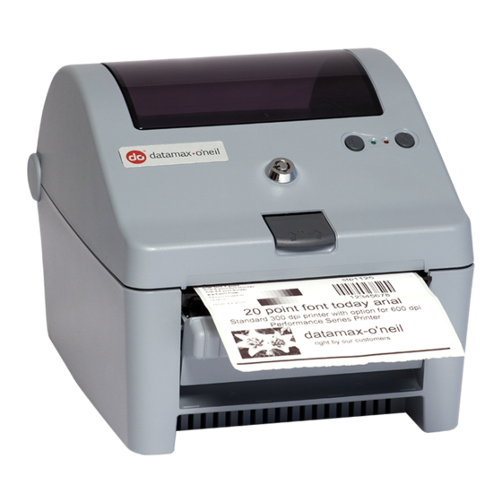
Overview Workstation Series Overview w1110 Product Tour The following illustrations show some of the features and available options for the printer. Figure: 2 - 1 Front View - w1110 1. Cover Latch Release 2. Stop/Resume 3. Power LED (Green) 4. Error LED (Red) 5. - Page 12 2 | Overview Figure: 2 - 2 Rear View - w1110 1. Power Switch 3. Reset Button 2. DC Power Inlet 4. USB 2.0 Port 5. Ethernet/Network Port Workstation Series User’s Guide...
- Page 13 Overview | 2 Figure: 2 - 3 Media Area 1. Printhead 6. Right Core Adapter 2. Upper Top-of-Form Sensor 7. Right Media Support Bracket 3. Cover Latch 8. Lower Top-of-Form Sensor 4. Left Media Support Bracket 9. Platen Roller 5. Left Core Adapter Workstation Series User’s Guide...
-
Page 14: Options
2 | Overview Options Figure: 2 - 4 Peel and Present 1. Peel Bar 2. Present Sensor Figure: 2 - 5 Serial Interface 1. Serial Interface Workstation Series User’s Guide... -
Page 15: Standard Features
Overview | 2 Standard Features The thermal printer has the following standard features: Table 1: Standard Features Features Descriptions Max Print Speed 4 IPS / 102 mmps Resolution 300 dpi / 11.8 dpmm Memory 32 MB Flash (4 MB User Space) / 64 MB DDR2 RAM Printer Type Direct Thermal Media Supply... -
Page 16: Options
2 | Overview Features Descriptions Printer Driver Supported • Windows XP Operating Systems • Windows Vista • Windows 7 • Windows 8 Operating Temperature 32°F (0°C) to 104°F (40°C) Options The following options are available: • Peel and Present • Serial Interface •... -
Page 17: Specifications
Overview | 2 Specifications Print Characteristics Table 2: Print Characteristics Variable Specifications Print Resolution 300 dpi (11.8 dpmm) Max Print Width 4.16” (105.7 mm) Max Print Speed 4 ips (102 mmps) Max Feed Speed 4 ips (102 mmps) Max Back-up Speed 4 ips (102 mmps) Media Width Range* 0.75”... -
Page 18: Configuration Utility
2 | Overview Minimum System Requirements Supported Operating Systems Windows XP - x86 & x64 Windows Vista - x86 & x64 Windows 7 - x86 & x64 Windows 8 Configuration Utility Table 6: Configuration Utility Minimum System Requirements Minimum System Requirements Processor / Speed 500 MHz processor Supported Operating Systems... -
Page 19: Connections And Setup
Connections and Setup Connections Power To connect the printer to a viable power source, please follow the steps below. Caution: Ensure the printer power switch is off before connecting the AC power and data/network connectivity cables to the printer. Caution: Adhere to all environmental requirements when installing and using the printer. -
Page 20: Media Loading
3 | Connections and Setup Connect the appropriate interface cables for your configuration. For network connection, the default is DCHP. *Note: To calibrate the printer sensors, remove paper and close the cover, then press and hold the rear panel reset switch together with both printer buttons simultaneously for five (5) seconds and release. - Page 21 Connections and Setup | 3 Note: The media core sizes are printed on the top of the core adapters. Figure: 3 - 1 Media Core Adapters 1.5” Media Core Adapter Locking Tabs b. Reinstall the core adapters with the corresponding number for the appropriate core size facing upwards.
- Page 22 3 | Connections and Setup Note: The paper must be wound out. Figure: 3 - 2 Paper Roll Installation 4. Release the media support brackets ensuring the core is secured by the core adapters. Workstation Series User’s Guide...
-
Page 23: Media Loading - Peel And Present
Connections and Setup | 3 5. Route the paper under the support bracket guides. Figure: 3 - 3 Support Bracket Guides Left Guide Right Guide 6. Close and latch the printer cover. 7. Feed the paper to find top-of-form. Note: When installing new media, perform a paper calibration to ensure the printer finds the top-of-form. - Page 24 3 | Connections and Setup 1. Open the peel and present sub-assembly. a. Rotate the peel and present sub-assembly forward. Figure: 3 - 4 Peel and Present Assembly 2. Load the media into the support bracket and the core adapters. 3.
- Page 25 Connections and Setup | 3 Note: Be sure there are no labels attached to the backing that is routed behind the peel and present sub-assembly. Figure: 3 - 5 Media Backing Label Backing 4. Pull the label backing tight to ensure proper tension of the label backing. 5.
-
Page 26: Control Panel
3 | Connections and Setup Control Panel The control panel consists of the two (2) main buttons on the printer cover, two (2) LEDs on the printer cover and the reset button on the back of the printer. All three are used to perform certain printer functions. -
Page 27: Buttons
Connections and Setup | 3 Light Printer State Green/Red Fast Alternating Blink - Recovery mode Combination Slow Alternating Blink - Upgrade in progress Slow Synchronized Blink - Cooling down or processing with a warning Synchronized Double Blink - Power-up in progress Buttons The operation of the buttons consists of long or short presses depending on the operation being performed. -
Page 28: Sensor Calibration
3 | Connections and Setup 2. Close and latch the printer cover. 3. Select the Stop/Resume button and the Feed/Cancel button together with long presses until the paper begins to move. Note: The media will advance through the printer verifying the top-of-form. Sensor Calibration Sensor calibration is set during the manufacturing process and may only need to be performed after upgrading the printer’s software or resetting defaults. -
Page 29: Print Driver Installation
The Windows driver is located on the Accessories CD-ROM included with the printer. For the latest version please visit our web site at http://www.datamax-oneil.com Installing the Windows Driver: 1. -
Page 30: Important Notes
‘Next’ and follow the on-screen instructions to install the driver. 7. When prompted, select your printer from the list, (i.e., Datamax-O’Neil w1110). Continue to follow the on-screen instructions to install the driver. Important Notes: The Windows driver functions the same as any other Windows printer. While built-in help... - Page 31 Connections and Setup | 3 Workstation Series User’s Guide...
- Page 32 3 | Connections and Setup Workstation Series User’s Guide...
-
Page 33: Operation
Operation Printer Modes The w1110 features three (3) modes: • Tear Mode • Present Sensor Mode • Pause Mode The modes are set in the printer’s configuration utility. Tear Mode Tear mode is used for most common print jobs and is the default mode for the printer. This mode is always used when Present Sensor Mode and Prompt Mode are not needed. -
Page 34: Reporting
4 | Operation The print job can be canceled by pushing the Feed/Cancel (right) button with a long press. The green LED will illuminate with a solid light indicating the printer ready state. Reporting The printer has a reporting feature that allows the user to print two different reports: •... - Page 35 Operation | 4 Settings Report The Settings Report provides information about the print settings including: Media Settings • Paper Sensor Type • Heat • Heat Balance • Gap/Mark Offset • Gap/Mark Noise • Number of Forms • Form Length Printer Settings •...
-
Page 36: Webpages
4 | Operation • Pitch Size • Symbol Set • Print Truncation • Print on Gap/Mark Auto Settings • Auto Option Detect • Auto Present Distance • Auto Speed Adjust Adjustment Settings • Present Distance Adjust • Vertical Adjust • Horizontal Adjust •... - Page 37 Operation | 4 Note: The printer’s IP address can be obtained by printing a System Report. Workstation Series User’s Guide...
- Page 38 4 | Operation Workstation Series User’s Guide...
-
Page 39: Cleaning And Maintenance
Cleaning and Maintenance Overview To maintain good print quality and increase printhead life, proper cleaning should be routinely performed using factory-approved cleaning supplies. Caution: A contaminated printhead can cause premature printhead failure. Caution: Failure to clean the printhead as detailed in this manual could void the printhead manufacturer’s warranty. - Page 40 5 | Cleaning and Maintenance Workstation Series User’s Guide...
-
Page 41: Troubleshooting
Troubleshooting LED Indicators The printer LEDs are also used to indicate errors and warnings. Refer to the following chart: Table 1: LED Indicators Action Green LED Red LED Notes Warning Not affected by Slow blink Warning Error Solid Control Mode Short blink with a Not affected Only applies when printer is in... -
Page 42: Warnings
6 | Troubleshooting Errors Description PRESENT SENSOR HARDWARE Present sensor hardware fault HEAD UP Printing or feeding with the cover open Note: To clear errors, open the printer cover fully and then close and latch it. Warnings Warnings Description MAINTENANCE REMINDER Maintenance timer has expired POWER SUPPLY HARDWARE Printhead voltage above maximum specifications... -
Page 43: Troubleshooting Print Quality
Hardware representative. The Present Sensor module may be Contact your technical support faulty. representative. Troubleshooting Print Quality Tools • Datamax-O’Neil approved media • Magnifying lens • Barcode verifier and grading system • Printhead cleaning card • Printhead cleaning pen Workstation Series User’s Guide... -
Page 44: Preliminary Instructions
6 | Troubleshooting Preliminary Instructions 1. Ensure the latest software has been loaded. 2. Load the media according to the instructions in the Setup section. Note: Verify that the paper is properly exiting the printer. 3. Print a Quality Label from the configuration utility or the printer control panel buttons. -
Page 45: Symbol Sets
Appendix A Symbol Sets The following Symbol Sets are available: Table 1: Symbol Sets Number Symbol Sets PC-8 Roman-8 Roman-9 ISO-L1 ISO-L2 ISO-L4 ISO-L5 ISO-L6 ISO-L9 PC-775 PS MATH MATH-8 PI FONT MS PUBL PC-8 DN PC-850 PC-852 PC-858 PC-8 TK PC-1004 WIN L1 WIN L2... -
Page 46: Fonts
7 | Appendix A Number Symbol Sets ISO-6 ISO-11 ISO-15 ISO-17 ISO-21 ISO-60 ISO-69 WIN 3.0 MC TEXT UCS-2 RomanExt Wingdings ZapDingBats Symbol Fonts The following Fonts are supported: Table 2: Fonts Font Escape Sequence CG Times <ESC>(<symset><ESC>(s1p<ptsize>v0s0b4101T CG Times Italic <ESC>(<symset><ESC>(s1p<ptsize>v1s0b4101T CG Times Bold <ESC>(<symset><ESC>(s1p<ptsize>v0s3b4101T... - Page 47 Appendix A | 7 Font Escape Sequence CG Omega <ESC>(<symset><ESC>(s1p<ptsize>v0s0b4113T CG Omega Italic <ESC>(<symset><ESC>(s1p<ptsize>v1s0b4113T CG Omega Bold <ESC>(<symset><ESC>(s1p<ptsize>v0s3b4113T CG Omega Bold Italic <ESC>(<symset><ESC>(s1p<ptsize>v1s3b4113T Garamond Antiqua <ESC>(<symset><ESC>(s1p<ptsize>v0s0b4197T Garamond Kursiv <ESC>(<symset><ESC>(s1p<ptsize>v1s0b4197T Garamond Halbfett <ESC>(<symset><ESC>(s1p<ptsize>v0s3b4197T Garamond Kursiv Halbfett <ESC>(<symset><ESC>(s1p<ptsize>v1s3b4197T Courier <ESC>(<symset><ESC>(s0p<pitch>h0s0b4099T Courier Italic <ESC>(<symset><ESC>(s0p<pitch>h1s0b4099T Courier Bold <ESC>(<symset><ESC>(s0p<pitch>h0s3b4099T...
-
Page 48: Barcodes
7 | Appendix A Font Escape Sequence Vera Regular Mono <ESC>(<symset><ESC>(s0p<pitch>h0s0b23410T Vera Italic <ESC>(<symset><ESC>(s0p<pitch>h1s0b23410T Vera Bold <ESC>(<symset><ESC>(s0p<pitch>h0s3b23410T Vera Bold Italic <ESC>(<symset><ESC>(s0p<pitch>h1s3b23410T CG Triumvirate <ESC>(<symset><ESC>(s1p<ptsize>v0s0b92244T CG Triumvirate Condensed Bold <ESC>(<symset><ESC>(s1p<ptsize>v4s3b92250T LinePrinter <ESC>(<symset><ESC>(s0p16.67h8.5v0s0b0T Barcodes The following barcodes are supported: Table 3: Barcodes Barcode Type Length... - Page 49 Appendix A | 7 Barcode Type Length Valid ASCII Characters, decimal value representation 1091 MSI Plessey Mod 10 1-55 1100 Code 93 1-107 0-9, A-Z, $,%,+,-,.,/,space 1110 HIBC Code 93 1-36 0-9, A-Z, $,%,+,-,.,/,space 1111 HIBC Code 128 1-36 0-9, A-Z, $,%,+,-,.,/,space 1120 Telepen 1-30...