Advertisement
Quick Links
Advertisement

Related Manuals for Datamax I-class series


Summary of Contents for Datamax I-class series
- Page 1 Operator’s Manual...
- Page 2 Important Safety Instructions The exclamation point within an equilateral triangle is intended to alert the user to the presence of important operating and maintenance instructions in the literature accompanying this unit. This unit has been carefully designed to provide years of safe, reliable performance. As with all electrical equipment, however, there are some basic precautions that you should follow to avoid personal injury or printer...
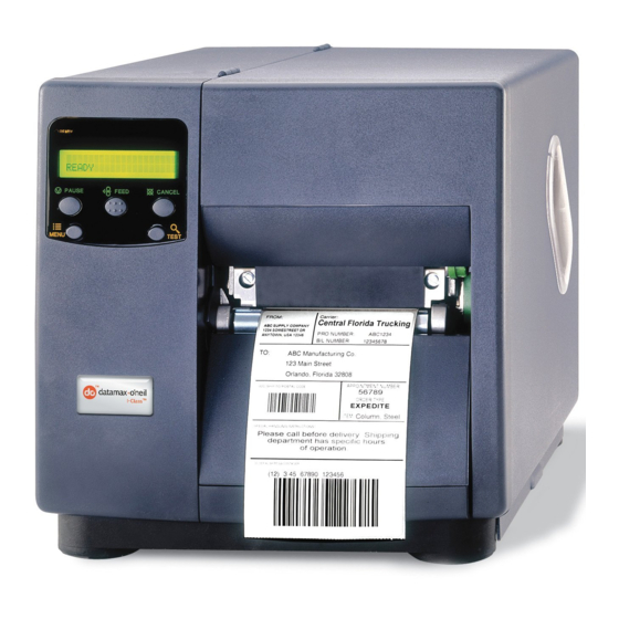
- Page 3 Overview 1.1 About the Printer Congratulations on your purchase of an I-Class printer (hereafter referred to as “the printer”). This manual provides information regarding printer setup, operation, and care. To print label formats, refer to the instructions provided with your labeling software; or if you wish to write custom programs, a copy of the Class Series 2 Programmer’s Manual can be found on the Accessories CD.
- Page 4 Standard Features I-Class Model Feature 4206 4208 4212 4308 4406 4604 Direct Thermal Printing Fan-Fold Media Handling Flash Memory Liquid Crystal Display Media Tear Bar Multi-Language Support On-Demand and Batch Printing Resolution (Dots Per Inch) Rotating Media Hub SDRAM 16MB 16MB 16MB 16MB...
- Page 5 External Keyboard (specify voltage & country requirement when ordering) A portable terminal for stand-alone printing. External Media Rewinder (specify voltage requirement when ordering) label A feature-dependant bidirectional rewinding device: DMXREW1 – rewinds widths up to 4.5 inches (114 mm) into eight-inch (203 mm) •...
- Page 6 A slide-in circuit card that provides a Universal Serial Bus (Version 1.1) interface for Windows printing environments. Option Installation Experience levels for option installations are detailed below. (Contact your dealer or Datamax-O’Neil Technical Support for more information.) Option Installations Option Recommended Installer Cutters / Trays –...
- Page 7 Option Installations (continued) Option Recommended Installer Peel and Present Mechanism Operator Present Sensor Operator RFID-Ready DMX Certified Technician RS-422 Serial Interface DMX Certified Technician Thermal Transfer Operator Twinax/Coax Interface DMX Certified Technician USB Port DMX Certified Technician I-Class...
- Page 8 Getting Started 2.1 Unpacking the Printer The printer has been carefully packaged to prevent transit damage. (Inspect the container for damage; if evident, notify the shipping company before acceptance.) Complete the steps below to ready the printer for use: A. With the arrow pointing upward, open the box. B.
- Page 9 Other items can also be needed for operation: An interface cable; see Section 3.1.1. • Applicable media; see Section 7.3. • Applicable software; consult the Accessories CD-ROM and see Appendix E for details, • or refer to your dealer or Datamax-O’Neil for information. I-Class...
- Page 10 Setting up the Printer 3.1 Installation Interface and connect power to the printer: A. Place the printer on a firm, level surface. B. Turn OFF the Host Computer then, depending upon your system, connect an appropriate interface cable from the host to the printer; see Section 3.1.1. C.
- Page 11 3.1.1 Communications Following power-up (or after a period of inactivity), interface port selection occurs automatically upon detection of valid data. If the incoming (received) data flow stops and the Host Timeout Value (see Section 4.2.6) is exceeded, partially received formats will be ignored and the port detection process repeated.
- Page 12 3.2 Media Loading Load media according to its type: A. Raise the cover. B. Rotate the Printhead Latch then raise the Printhead Assembly. C. Slide the Media Guide outward and then rotate it downward. D. If using roll media on a 1.5-inch (38mm) core, grasp then pull firmly outward to remove the 3-Inch Media Hub;...
- Page 13 3.2.1 Loading Roll Media A. Slide the Roll Media onto the Media Hub until it reaches the Backstop. Backstop Roll Media Media Hub Media Guide B. Route the Media under the Media Idler, through the Media Sensor, and then straight out the front of printer.
- Page 14 E. If using thermal transfer media, load ribbon (see Section 3.4); otherwise, go to Step F. F. Lower the Printhead Assembly and rotate the Printhead Latch into the locked position. Close the cover then turn ON the printer. After READY is displayed, press and hold the FEED Key until at least one label gap (or mark) is advanced;...
- Page 15 B. Route the Media under the Media Idler (also, if equipped over the Internal Rewinder; and, if through the Rear Media Slot, over the Media Hub). Media Idler Media Media Sensor Media Internal Rewinder Media (Optional Equipment) Guide C. Pass the media through the Media Sensor then straight out the front of the printer. D.
- Page 16 3.3 Media Sensor Adjustment The Media Sensor detects media presence, and top-of-form (except when using continuous stock). Adjust the Media Sensor as follows: A. With media loaded and the Printhead Assembly raised for visual access, grasp the Slide Tab of the Media Sensor. B.
- Page 17 3.4 Ribbon Loading The Thermal Transfer Option type determines the applicable ribbon type [Coating Side In (CSI) or Coating Side Out (CSO)]. Depending upon the option type, load ribbon as follows: A. Unlock the Printhead Latch and raise the Printhead Assembly. Following the Directional Arrows on the Thermal Transfer Option, orient the Ribbon Roll accordingly and then slide it completely onto the Ribbon Supply Hub.
- Page 18 Removing Used Ribbon When the Ribbon Roll is depleted, pull the empty core from the Ribbon Supply Hub. Grasp the used roll on Ribbon Take-Up Hub then pull and squeeze to remove the spent ribbon. (To remove partially depleted rolls, cut the ribbon then remove the roll and discard any used ribbon as described above.) 3.5 Quick Calibration The printer is calibrated to sense a wide range of media.
- Page 19 Using the Control Panel 4.1 Operation The Control Panel is composed of a display, indicators, and mode-dependant keys for easy access to printer functions. 4.1.1 Display and Indicator Lights Liquid Crystal Display (LCD) The LCD provides textual information: STOP ERROR READY Following initialization, the READY message;...
- Page 20 4.1.2 Ready Mode: Normal Operation (Ready Light ON) The PAUSE Key temporarily suspends printing, and pressing it again returns normal operation. The FEED Key advances labels, and clears any corrected faults. Pressing and holding it initiates calibration; see Section 3.5.
- Page 21 The ESCAPE Key moves through previous menu levels to Ready Mode. The TEST Key terminates printing then restores Menu Mode. 4.1.4 Test Mode: Printing Test Labels The DOWN ARROW Key scrolls to the previous test function. The UP ARROW Key scrolls to the next test function.
- Page 22 4.2 The System Menu The MENU Key accesses seven system branches: MEDIA SETTINGS • PRINT CONTROL • PRINTER OPTIONS • SYSTEM SETTINGS • COMMUNICATIONS • DIAGNOSTICS • MCL OPTIONS • Notes: (1) Entering the menu takes the printer offline and halts the processing of new ...
- Page 23 Displayed Message Details MENU MODE The Menu Key has been pressed, where: ENTER PASSWORD Requires entry of the correct security password for menu access. 0 0 0 0 KEEP HOST CHANGES? Requires a decision regarding existing host commands that have affected the configuration of the printer, ENTER=YES where pressing ENTER will save these changes or pressing ESC will discard them.
- Page 24 Media Settings (continued) Menu Item Details SENSOR TYPE Selects the Top Of Form (TOF) sensing method used to determine the leading edge of the label, where: Senses the gaps or notches in the media. GAP CONTINUOUS TOF sensing is not used; see LABEL LENGTH. REFLECTIVE Senses the reflective (black) marks on the underside of the media.
- Page 25 Media Settings (continued) Menu Item Details PAUSE ON RIBBON LOW Sets the printer to pause when the RIBBON LOW DIAMETER setting is met, where: ENABLED Forces the user to press the PAUSE Key to proceed with the print job. Allows printing to continue until ribbon empty is DISABLED declared.
- Page 26 4.2.3 Print Control The Print Control menu contains print quality, throughput, formatting, and custom setup functions: Menu Item Details HEAT Controls the burn-time of the printhead (selectable as “Heat” in most labeling programs), where: (0 - 30) Is the number based on duration, corresponding to 10 print darkness.
- Page 27 Print Control (continued) Menu Item Details PRESENT DISTANCE Sets the label stop position, where: (0 - 4.00) Is the label travel distance at output. 0.00in MOTOR THROTTLING Controls the current to the stepper motor, where: Counts labels versus time and, if needed, pauses ENABLED printing to maintain a cooler motor temperature.
- Page 28 4.2.4 Printer Options The Printer Options menu contains module, file-handling, and option functions: Menu Item Details MODULES Controls memory handling functions, where: PRINT DIRECTORY Prints a listing of available space, files, and types; see Appendix A. PRINT FILE Prints from a list of available files. FORMAT MODULE Formats the selected module, erasing all data.
- Page 29 Printer Options (continued) Menu Item Details CUT BEHIND Allows a number of small labels to queue before a cut is performed, increasing throughput, where: Note: This mode can be used without a cutter to allow the presentation of an extra label, with retraction occurring upon the next job or feed operation.
- Page 30 Printer Options (continued) Menu Item Details BARCODE COUNT Specifies a number of bar codes per label and generates a fault when the number present is incorrect, where: (0 - 99) Sets the number of bar codes to count, where 00 (Auto 00 Mode) allows a variable number.
- Page 31 Printer Options (continued) Menu Item Details RFID Controls the RFID operation, where: RFID MODULE Sets the mode of RFID operation, where: Disables RFID. DISABLED Selects the Securakey option. UHF CLASS 1 Selects the Alien option. UHF MULTI-PROTOCOL Selects the UHF cross-platform option. RFID POSITION Sets the RFID encoding position, where: (110 - 4.00)
- Page 32 Printer Options (continued) Menu Item Details DSFID LOCK Locks the DSFID value, where: Is not protected. DISABLED ENABLED Is write-protected. EAS VALUE Selects the Electronic Article Surveillance value, where: (HEX) Is the value (00 - FF). 00 AUDIO INDICATOR ERASE ON FAULT Allows tag data erasure when errors are detected, where: Keeps data.
- Page 33 Printer Options (continued) Menu Item Details KILL CODE Code to permanently deactivate the tag, where: 00 00 00 00 Is the code, in the form B3, B2, B1, B0. ACCESS CODE Code to protect tag memory contents, where: 00 00 00 00 Is the code, in the form B3, B2, B1, B0.
- Page 34 Printer Options (continued) Menu Item Details RETRY ATTEMPTS Sets the number of retry attempts, where: (0 - 9) Is the retry count before a fault is declared. 3 AUTO DETECT TAG Allows the printer to establish the tag to transducer distance setting.
- Page 35 Printer Options (continued) Menu Item Details START OF PRINT Selects the type of input signal required to initiate printing, where: ACTIVE HIGH Triggers printing with a high signal. EDGE Triggers printing with a signal edge transition. LOW PULSE Triggers printing with a low pulse. HIGH PULSE Triggers printing with a high pulse.
- Page 36 Printer Options (continued) Menu Item Details BACKUP LABEL Positions a presented label for printing (provided the PRESENT DISTANCE setting is greater than zero), where: Disables backup positioning. DISABLED ACTIVE LOW Positions the label when a logic low is received. ACTIVE HIGH Positions the label when a logic high is received.
- Page 37 System Settings (continued) Menu Item Details INTERNAL MODULE D Allocates a number of 1KB memory blocks for internal Memory Module D; where: 1024 K (XXX - XXXX) Is the memory allocation; see Appendix A for the memory ranges, types, and availability. DEFAULT MODULE Designates the memory module for storage when no other location is specified;...
- Page 38 System Settings (continued) Menu Item Details MEDIA COUNTERS Provides a recorded count of inches printed and time; where: ABSOLUTE COUNTER Shows the total number of inches printed and the set date. (Non-resettable) RESETTABLE COUNTER Shows the number of inches printed and the last reset date.
- Page 39 System Settings (continued) Menu Item Details UNLOCK FEATURE Unlocks a corresponding feature with the entry of the correct code. 0 0 0 0 0 0 SET FACTORY DEFAULTS Returns the printer settings to the factory-programmed values or the Factory Setting File values, where: SET FACTORY DEFAULT? Overwrites the current configuration and restores the default configuration (), or if selected the Factory...
- Page 40 System Settings (continued) Menu Item Details PEEL MODE Allows the SOP signal to initiate (via GPIO option) the feeding of the labels, where: Feeds regardless of SOP. DISABLED ENABLED Feeds only when SOP is received. Allows menu password protection, where: SECURITY SELECT SECURITY Enables or disables the security feature, where:...
- Page 41 System Settings (continued) Menu Item Details AUTO Identifies then activates the appropriate emulation parser for the data. Note: Correct identification can be dependant upon the HOST SETTINGS / HOST TIMEOUT (see Section 4.2.6). Also, extraneous characters may, in some cases, render the data unrecognizable, thus requiring manual selection of the mode.
- Page 42 System Settings (continued) Menu Item Details MODE Repositions media, where: Moves media only when the next label is ready to print, DISABLED minimizing edge curling. ENABLED Moves media according to BACKUP DELAY timing after a cut, cleared sensor, or SOP signal to allow fastest throughput.
- Page 43 System Settings (continued) Menu Item Details FAULT HANDLING Determines the label disposition and user action if a fault occurs, where: LEVEL Sets the printer response upon declaration of a fault, where: Stops printing and declares a fault. Then, following STANDARD correction of the problem, the FEED Key must be pressed to clear the fault and reprint the label in process.
- Page 44 System Settings (continued) Menu Item Details VOID DISTANCE Sets the distance to print VOID on a faulted label, where: (10 – 2.00) Is the distance, measured from the trailing edge, which 0.50in establishes the text size. Note: VOID will not be printed if insufficient text ...
- Page 45 Communications (continued) Menu Item Details 9600 BPS 19200 BPS 28800 BPS 38400 BPS Is the speed in Bits Per Second. 57600 BPS 115000 BPS 1200 BPS 2400 BPS 4800 BPS PROTOCOL Sets the data flow control (handshaking) method. Uses XON/XOFF and CTS/DTR flow control. BOTH SOFTWARE XON/XOFF...
- Page 46 Communications (continued) Menu Item Details SERIAL PORT D Controls the RS-232 communications settings for optional Serial Port D; see SERIAL PORT A. Note: The maximum baud is 38.4K BPS. PARALLEL PORT A Controls the communications settings for Parallel Port A, where: PORT DIRECTION Allows data return from the printer, where:...
- Page 47 Communications (continued) Menu Item Details WLAN ADHOC? Restores the WiFi defaults and initiates infrastructure mode with an SSID of “Any.” All existing access point CANCEL KEY = YES associations will be deleted then established with the closest available. (Useful when moving the printer to a geographically distant location.) Note: Press the ESC Key to exit the menu item ...
- Page 48 Communications (continued) Menu Item Details SNMPTRAP DESTINATION Specifies the SNMP Trap Address, where: 000.000.000.000 Is the address in standard octet format where SNMP traps will be sent when SNMP service is installed on your receiver. Note: When zeroed, no traps are sent. ...
- Page 49 Communications (continued) Menu Item Details Sets the Maximum Transmission Unit packet size, where: Is the packet size, in bytes. 01500 (512 - 65515) GRATUITOUS ARP Sets the Address Resolution Protocol notification rate, where: Is the time, in minutes. 0000 (0 - 2048) PORT NUMBER Sets the network communications port, where: 09100 (1 - 65535)
- Page 50 Communications (continued) Menu Item Details SET FACTORY DEFAULTS Returns the NIC to factory-programmed values, where: SET FACTORY DEFAULTS? Restores the default settings. CANCEL KEY = YES Note: Press the ESC Key to exit the menu item without changing the current settings. HOST SETTINGS Sets host communication parameters;...
- Page 51 Communications (continued) Menu Item Details HEAT COMMAND Determines how a host software Heat command is handled, where: Processes commands normally. ENABLED DISABLED Ignores commands; instead, Heat is controlled via the menu setting; see Section 4.2.3. SPEED COMMANDS Determines how host software Print, Feed, Reverse, and Slew commands are handled, where: Processes commands normally.
- Page 52 Communications (continued) Menu Item Details MAX LENGTH COMMAND Determines how a host software Maximum Label Length (<STX>M) command is handled, where: Processes commands normally. ENABLED DISABLED Controls the setting via the menu; see Section 4.2.2. OPTION FEEDBACK Allows feedback characters from an optional device to be returned to the host device, in the format of <A;B;C;D;E;F>[CR], where: A - Is the device type: R = RFID;...
- Page 53 4.2.7 Diagnostics The Diagnostics menu contains testing functions: Menu Item Details HEX DUMP MODE Allows raw code received from the host to print, where: Executes commands and prints label formats normally. DISABLED ENABLED Prints received data without processing; see Section 6.2.
- Page 54 Diagnostics (continued) Menu Item Details LOOPBACK Not Supported PRINT SIGNAL INFO Prints signal names, pin assignments, settings, and current states for reference. GPIO SIGNAL INFO WED 11:04AM 24MAR2003 CARD ID#1 OUTPUT SIGNALS INPUT SIGNALS END OF PRINT START OF PRINT PIN# 8 PIN# 6 ACTIVE HIGH...
- Page 55 Diagnostics (continued) Menu Item Details SENSOR READINGS Displays A-D sensor values (0 – 255), where: THR TRAN RIBM 24V Are the sensor readings, where: THR = Printhead thermistor sensor; • TRAN = Media sensor when set to Gap or Continuous, or •...
- Page 56 4.3 The Test Menu The TEST Key accesses six resident format selections that are printed at selected heat and speed settings (see Section 4.1.4 for printing details). Notes: (1) With the exception of the Configuration Label, all test labels require full ...
- Page 57 4.3.3 Ribbon Test Label The Quick Ribbon Test Label can be used to verify thermal transfer functions. 4.3.4 Validation Label The Validation Label can be used to verify print quality. 4.3.5 Print Last Label The Print Last Label function reprints the most recent test label, format received from the host, or format recalled from a memory module.
- Page 58 Operating, Adjusting and Maintaining the Printer 5.1 Displayed Messages During operation the printer (when not in Menu or Test Mode) displays several types of information: Prompts and Condition Messages (see Section 5.1.1); and, • Fault and Warning Messages (see Section 6.1.2). •...
- Page 59 Prompts and Condition Messages (continued) Displayed Message Description Action The MENU Key is being pressed Release the MENU Key DISPLAY CONTRAST and held, and now the LCD when the desired contrast is being adjusted. contrast is achieved. No action is required. The network card is initializing, a Depending upon the DMXNET INITIALIZING...
- Page 60 Prompts and Condition Messages (continued) Displayed Message Description Action No action is required. The power switch has been turned SYSTEM INITIALIZING Wait briefly while the ON or a reset has occurred. process completes. No action is required. SYSTEM RESET A reset has occurred. Wait briefly while the IN PROGRESS process completes.
- Page 61 Three samples are required: Empty: Nothing in the sensor. • Gap (or Mark): The media liner, notch, or reflective mark in the sensor. • Paper: The label (and liner, if any) in the sensor. • With the correct SENSOR TYPE selected (see Section 4.2.2), perform a Standard Calibration as follows: Step Action...
- Page 62 Standard Calibration (continued) Step Action Displayed Message Comment Proceed according to your media: Die-cut – remove a label See Section 3.3 for from the backing sensor positioning material then place the details. backing in the sensor. Adjust the Sensor Eye Mark over the center of the backing.
- Page 63 Standard Calibration (continued) Step Action Displayed Message Comment GAP MODE CALIBRATION COMPLETE The calibration was Or, for reflective media: successful if CALIBRATION COMPLETE REFLECTIVE MODE appears. Observe the LCD. CALIBRATION COMPLETE (If, however, another Or, for continuous media: message was displayed see Note 1, below.) CONTINUOUS MODE CALIBRATION COMPLETE...
- Page 64 5.2.2 Advanced Entry Calibration Advanced Entry is the alternate calibration method for special-case media types. In the procedure, sensor readings for the label and TOF values are taken using different sampling algorithms. From this compiled list of values the best algorithm is selected and then used to generate new readings for manual entry into memory.
- Page 65 Advanced Entry Calibration (continued) Step Action Displayed Message Comment See Section 3.3 for GAIN TRAN <yyy> sensor positioning Press the Key. <0 - 31> details. Place the label under the If using preprinted Or, for reflective media: Sensor Eye Mark, and then media, ensure the label lower the printhead area under the Sensor...
- Page 66 Advanced Entry Calibration (continued) Step Action Displayed Message Comment Proceed according to your media type: Die-cut – remove a label from the backing material then place the backing into the sensor. Adjust the Sensor Eye Mark over GAIN TRAN <yyy> the center of the backing.
- Page 67 Advanced Entry Calibration (continued) Step Action Displayed Message Comment Press the Key to GAIN TRAN <yyy> increment the Gain Number <0 - 31> then press the and record the resulting TOF Value. Or, for reflective media: Repeat this step for each of GAIN REFL <yyy>...
- Page 68 Advanced Entry Calibration (continued) Step Action Displayed Message Comment a) Place the media in the sensor. Record the reading and label it “P” GAIN TRAN <yyy> (paper). <0 - 31> b) Place the backing, notch, The samplings using the or mark in the sensor. selected Gain Number Record the reading and Or, for reflective media:...
- Page 69 Advanced Entry Calibration (continued) Step Action Displayed Message Comment After all entries have been made, press the From READY, press the SAVE CHANGES? to back out of the menu and FEED Key to advance to ENTER KEY = YES then press the the next label TOF.
- Page 70 5.4 Printhead Assembly Adjustments Mechanical adjustments ensure consistent print quality across a wide range of media types and sizes. 5.4.1 Leveling Cam Adjustment Adjust the Leveling Cam for even pressure distribution when using less than full width media [4 inches (102mm)]; in addition, perform the adjustment when changing to a different width of media: A.
- Page 71 Note: If you have questions regarding this procedure, contact a qualified technician or Datamax-O’Neil Technical Support for answers. A. Load the printer with your media (and ribbon, if required) then lower the printhead assembly and rotate the printhead latch into the locked position.
- Page 72 CAUTION have any questions regarding this procedure, contact a qualified technician or Datamax-O’Neil Technical Support for answers. Follow the procedure below to replace the printhead: A. Touch a bare metal area of the printer’s frame to discharge any static electricity present on your body.
- Page 73 C. With the printhead locked in the down position, loosen the Printhead Mounting Screw (it will remain in the assembly). D. Rotate the printhead latch forward and, while supporting the Printhead, raise the Printhead Assembly. Disconnect the Cables and then remove the Printhead. E.
- Page 74 5.6 Maintenance The following list and table detail the recommended items, techniques, and schedules to help you safely and effectively maintain the printer: Isopropyl alcohol • Cotton swabs • A clean, lint-free cloth • Soft-bristle brush • Soapy water/mild detergent •...
- Page 75 Note: Streaks can indicate a dirty or faulty printhead. Proper cleaning is critical. To maintain peak performance of the printer, Datamax O’Neil offers a complete line of cleaning products including pens, cards, films and swabs. Cotton Swab Procedure...
- Page 76 B. Move media (and ribbon, if present) away from the printhead, as necessary. Using a cotton swab moistened (not soaked) with isopropyl alcohol, gently wipe away buildup on the Printhead while paying special attention to cleaning the Burn Line. Allow the printhead to dry.
- Page 77 5.6.2 Cleaning the Platen Roller NEVER use a sharp object to clean the Platen. CAUTION Grit, adhesive, and ink buildup can cause a decline in print quality and, in extreme cases, cause labels to stick and wrap around the roller. Clean the platen roller as follows: A.
- Page 78 5.6.3 Cleaning Interior and Exterior Surfaces Interior Surfaces – Turn OFF and unplug the printer. Remove all media. Then, using a soft bristle brush or compressed air, remove all dust particle buildup inside the printer. Exterior Surfaces – Turn OFF and unplug the printer. Remove all media. Then, using a soft cloth or sponge dampened with general-purpose cleanser (never abrasive cleansers or solvents) wipe the exterior surfaces until clean.
- Page 79 5.7.1 Updating from Ready Mode Application Version 2.091 (or greater) Update Procedure Step Displayed Message Action Comment(s) As an example, this would Using the DOS copy be entered as: command (where “filename” is the program copy i4212_1105.zg lpt1 to be loaded and “lpt1” is the selected interface READY (Where “lpt1”...
- Page 80 5.7.2 Updating from Download Mode Application Version 2.08 (or less) Update Procedure* Step Displayed Message Action Comment(s) The Boot Loader version is Turn OFF the printer. displayed. BOOT–PA10 Press and hold the PAUSE Note: This information will 02.08 2/11/00 Key and TEST Key while vary with the printer model and turning ON the printer.
- Page 81 1) Use the Download Mode (see Section 5.7.2). 2) Windows users – try restarting the computer in MS-DOS mode. 3) Use the Datamax-O’Neil Driver by Seagull Scientific™ – Device Setting / Send File to Printer function. I-Class...
- Page 82 5.8 Boot Loader Updates The printer stores its Boot Loader program in Flash memory on the main logic card. If power is lost while UPGRADING SOFTWARE is displayed, the printer will become non-functional and will require factory programming or a main logic card.
- Page 83 Section 6.1.2. Note: If you have questions, or if problems persist, contact a qualified technician or Datamax-O’Neil Technical Support. 6.1.1 General Resolutions The following table lists problems that may not be accompanied by a displayed message: If experiencing this Try this solution…...
- Page 84 General Resolutions (continued) If experiencing this Try this solution… problem… Erratic media The printer may require a calibration – See Section 3.5. movement: The printer may be in Hex Dump Mode – See Section 6.2. • Erratic printing (instead of the label format, If using the serial communication the port settings may be •...
- Page 85 General Resolutions (continued) If experiencing this Try this solution… problem… The LCD is off, but The Display Contrast may set too low – Press and hold the indicator lights are MENU Key; see Section 4.1.1. illuminated: Verify that the AC power cord is connected to the outlet and •...
- Page 86 General Resolutions (continued) If experiencing this Try this solution… problem… Ensure that the printer is at READY. • Send the job again while observing the Ready Indicator • Nothing happens when (see Section 4.1.1.) – If the indicator does not flash, check printing from your the printer and host for protocol and port settings.
- Page 87 6.1.2 Warning and Fault Messages The printer displays messages when the possibility of a problem or an actual fault occurs. Depending upon the displayed message, find the possible action or solution in the tables below. Note: Warning and Fault Messages do not appear in Menu or Test Mode. ...
- Page 88 Warning Messages (continued) Warning Messages Displayed Message Description Action(s) Possible low or fluctuating line • voltage level – Try moving the printer to another AC outlet; if the condition persists, call for service. The printer has detected LOW VOLTAGE a low operating voltage. If printing black over more •...
- Page 89 Fault Messages (continued) Fault Messages Displayed Message Description Action(s) WARNING! Use extreme care. Turn OFF and unplug the printer before proceeding. The printer has detected Examine the cutter for CUTTER FAULT a cutter mechanism obstructions and ensure its cable fault. is properly connected.
- Page 90 Fault Messages (continued) Fault Messages Displayed Message Description Action(s) Try the following procedures: Load media. Ensure that the • labels are passing through the Media Sensor and, if necessary, readjust the Media The printer cannot detect Sensor over the TOF mark; OUT OF STOCK media.
- Page 91 Fault Messages (continued) Fault Messages Displayed Message Description Action(s) Press any key to continue. Ensure that the reflective mark is inserted facedown in the media sensor during calibration; also, REFLECTIVE MODE Consistently low sensor ensure that the reflective mark is CANNOT CALIBRATE readings were detected.
- Page 92 Fault Messages (continued) Fault Messages Displayed Message Description Action(s) Press the FEED Key to clear. If the bar code is free from anomalies (e.g., voids, insufficient quiet zones, etc.) yet the fault continues, try the following: 1) Ensure that the bar code is capable of being read by the scanner;...
- Page 93 Fault Messages (continued) Fault Messages Displayed Message Description Action(s) If media is moving: 1) Press the FEED Key. It may be necessary to re-calibrate the printer; see Section 5.2. 2) The Media Sensor may be out of position. Readjust it; see Section 3.3.
- Page 94 After sending a label format to the printer, the output will be immediate (see sample below). As a final note, many software programs use bit mapping to construct the format, making diagnosis difficult. Contact Datamax-O’Neil Technical Support with any questions. Note: To return to Ready Mode, re-enter the DIAGNOSTICS and disable HEX DUMP ...
- Page 95 Specifications 7.1 General Bar Codes Code 39, Interleaved 2 of 5, Code 128 (subsets A, B and C), Codabar, LOGMARS, UPC-A, UPC-E, UPC 2 & 5 digit addendums, EAN-8, EAN-13, EAN 2 & 5 digit addendums, UPC Random Weight, Code 93, Plessey, Universal Shipping Container Symbology, Code 128 MOD 43, Postnet, USS/EAN-128 Random Weight, Telepen, USD-8 (Code 11), UPS MaxiCode (modes 2 &...
- Page 96 Environmental Operating Temperature: 32 F – 100 F (0 C to 38 C) Storage Temperature: 0° F – 140° F (-17° C to 60° C) Humidity: 10% – 95% non-condensing Dust: Non-conducting, non-corrosive Electromagnetic Radiation: Moderate RF fields can be tolerated Mechanical Height: 12.70 inches (322.6 mm)
- Page 97 Printing (continued) Maximum Print Width: 4.10” (104.0 mm): I-4206, I-4208, I-4212 4.16” (105.7 mm): I-4308 4.10” (104.0 mm): I-4406 4.16” (105.7 mm): I-4604 Print Length Range: .25”- 99” (6.4 - 2514.6 mm): I-4206, I-4208, I-4212, I-4308 .25”- 84” (6.4 - 2133.6 mm): I-4406 .25”- 55”...
- Page 98 To achieve optimum print quality and maximum printhead life, DATAMAX-O’NEIL brand media and ribbons must be used. These supplies are specially formulated for use in this printer. The use of non-Datamax-O’Neil supplies may affect the print quality, performance, and life of the printer or its components (see the Warranty Statement).
- Page 99 7.2.2 Media and Ribbon Requirements Suggested applications are listed in the following table (and for specific information consult a Datamax-O’Neil Media Representative or other qualified specialist): Media and Ribbon Overview Ribbon Print Print Image Thermal Transfer Type Speed* Energy Durability...
- Page 100 Dimensional Requirements are listed in the following table: Side View Top View Media Dimensional Requirements Designator Description Minimum Maximum Label width 1.00 4.65 Liner width 1.00 4.65 Gap (or notch) between labels – Label length – Media thickness .0025 .010 Notch opening width .500 Media edge to sensor aperture distance...
- Page 101 7.3 Serial Cable Requirements Wiring diagrams, suggested applications, and part numbers for serial interface cables are given in the table below. (Contact a reseller for ordering information.) Applicable Serial Interface Cables Null Modem (MXM) “PC” (DB9P) to Printer Part Number 556000 Part Number 556001 For connection to a PC compatible with For connection to other DCE equipment.
- Page 102 Appendix A Module Assignments Memory Module Designator Module Size Volatile* Location / Use 1024 KB Main logic card SDRAM – for graphics, fonts, and (default size) formats Optional GPI/O Multi-Expansion Card – for 4 MB graphics, fonts, and formats Main logic card Flash – for graphics, fonts, and 256 KB formats (all models except I-4206 and I-4208).
- Page 103 Available Speeds and Default Settings Printer Speed Ranges and Defaults* Speed Range Default Setting Model Function MMPS MMPS Print 2 – 6 51 – 152 Feed 2 – 8 51 – 203 I-4206 Reverse 2 – 4 51 – 102 Slew 2 –...
- Page 104 Appendix B Custom Adjustment Ranges Row, Column, and Present Adjust Ranges (in dots) Column Adjust, Default Model Row Adjust and Present Adjust Setting I-4206, I-4208, & I-4212 -100 – 2030 -100 – 100 I-4308 -150 – 3000 -150 – 150 I-4406 -200 –...
- Page 105 Appendix C Menu Multi-Language Support The printer allows new menu languages and / or replacement of the Datamax-O’Neil provided translations. A Microsoft Excel Spreadsheet defines the menu dictionary and a new language column is added or an existing column modified. Then, by clicking on the “Generate DPL file(s)”...
- Page 106 Creating a Menu Language: Invoke Excel and open the gemmsglst.xls file. Excel opens the file and the following screen appears. Click the “Enable Macro” box and the following appears: Click On Column J and enter your new language, or modify an existing one. Tips: A) Message Size –...
- Page 107 C) Comments – This field can be modified with no effect. When editing has been completed, highlight all of the columns you desire to create (more than one language may be selected) by pressing the letter above the column. ...
- Page 108 To restore the factory generated EFIGS image, download the file *832296.01A to the • printer. This file is located on the Datamax-O’Neil FTP site. The letter at the end of the file name (e.g., A) specifies the revision. The latest revision will be available on the FTP site.
- Page 109 Appendix D Configuration Files With application version 5.01 and above, the printer can save and restore complete printer settings, including media calibration parameters, in internal Configuration Files. Here are the highlights and restrictions of the feature: Eliminates the need to repeat the manual steps of a special printer setup, making •...
- Page 110 Follow the steps below to save a manually entered setup as a configuration file: Step Displayed Message Action Comment You are entering MENU READY Press the Key. MODE. Use the Key to Key can also MENU MODE scroll to SYSTEM be used.
- Page 111 Appendix E Printer Driver and Port Setup Install the Printer Driver and Port software according to the host’s operating system. The example below highlights the driver Windows XP; other installations will be similar. installation for Windows XP Driver and Port Installation Start the Windows Ensure that Local “Add Printer...
- Page 112 Windows XP Driver and Port Installation (continued) In the Printer Name Ensure Standard is or IP Address field selected and then enter the IP click Next. address of your printer. The Port Name field does not need to be changed. When finished click “Next”.
- Page 113 Windows XP Driver and Port Installation (continued) Click OK. Select your printer from the list and then click Next. Name your printer Select whether or in the Printer not to share this name: field. Next printer on your select whether or network.
- Page 114 Windows XP Driver and Port Installation (continued) If prompted with Your computer will the "Digital now copy the Signature Not necessary files from Found" window, the CD-ROM. click “Continue The driver and port Anyway” to installation is now continue complete. The installation.
- Page 115 Glossary alphanumeric Consisting of alphabetic, numeric, punctuation and other symbols. backing material The silicon-coated paper carrier material to which labels with adhesive backing are affixed (also referred to as “liner”). bar code A representation of alphanumeric information in a pattern of machine-readable marks.
- Page 116 (also referred to as “resolution”). DPL (Datamax-O’Neil Programming Language) programming commands used specifically for control of and label production in Datamax-O’Neil printers. A complete listing of commands can be found in the Class Series 2 Programmer’s Manual.
- Page 117 on demand An output regulator (i.e., the Present Sensor) that inhibits printing when a label is already present. preprinted media Label stock that contains borders, text, or graphics, floodcoating, etc. perforation Small cuts extending through the backing and/or label material to facilitate their separation (also referred to as “perf”).
- Page 118 Operator’s Manual...
- Page 119 Congratulations on your I-Class Mark II printer purchase. The I-Class Mark II printer family, hereafter referred to as ‘the printer’, blends the rugged durability of die-cast construction with state-of-the-art electronics and user-friendly features to redefine the standard in industrial thermal printers. This manual provides all the information necessary to operate the printer.
- Page 120 2.1.1 Power Connection Before connecting the AC Power Cord or interface cables to the printer, ensure the Power On/Off Switch is in the ‘Off’ position. Place the printer on a firm, level surface. Ensure that the Power Switch on the Printer is in the ‘Off’ position. Connect the AC Power Cord to the receptacle on the back of the Printer, and then plug the AC Power Cord into a properly grounded outlet.
- Page 121 2.1.2 Interface Connection The printer can be connected to the host via the parallel, USB, serial, or optional network interface. The printer will automatically connect to the first port that delivers valid data. Once established, the printer’s power must be cycled ‘Off’...
- Page 122 Load media into the printer as follows: 1. Open the media cover. Rotate and unlock the Printhead Latch and raise the Printhead Assembly. 2. Rotate the Media Guide down. Printhead Latch Printhead Assembly Media Guide 3. Slide the Roll Media onto the Media Hub. 4.
- Page 123 5. Close the Printhead Assembly and rotate the Printhead Latch to the locked position. 6. Close the cover and press the FEED button several times to position the media and ensure proper tracking. Printhead Assembly Printhead Latch If the printer does not correctly sense the top of each label, it may be necessary to calibrate the printer (see Section 3.4 Media Calibration).
- Page 124 The Media Sensor needs to be positioned so that the printer can detect the presence of media and the top-of-form (except for continuous stock, where the TOF is set through the front panel). To adjust: 1. With media loaded, as described in Section 2.2, grasp the Slide Tab and move the Sensor Eye Mark into position over media according to the table below.
- Page 125 Ribbon is required with thermal transfer media. It is recommended that the width of the ribbon be slightly wider than the media being used. The printer can use either ribbons with the ‘coating side in’ or ribbons with the ‘coating side out’. To load: Using a ribbon that is slightly wider than your media (and liner, if any) will help protect against •...
- Page 126 Ribbon Routing Diagrams (CSI) ‘Coating Side In’ Ribbon Routing (CSO) ‘Coating Side Out’ Ribbon Routing...
- Page 127 3. Route the ribbon under the Ribbon Idler and then out the front of the printer approximately 12 inches as shown. Ribbon Roll Ribbon Supply Hub Ribbon Idler 4. Close the Printhead Assembly and rotate the Printhead Latch to the locked position. Route the ribbon up and then around to the Ribbon Take-Up Hub, winding it several times in a clockwise direction to secure it in place.
- Page 128 The OPTIMedia function is designed to reduce set up time when using Datamax-O’Neil branded media and ribbons. This feature enables the printer to automatically adjust print heat and print speed settings to optimum levels to produce the best possible print quality. By using the model number prefix of the media and ribbon (printed on the shipping box), the printer can be quickly configured to produce optimum print quality for that particular media and ribbon combination.
- Page 129 When equipped with the Internal Rewind option, labels can be rewound or, with the addition of a Peel and Present option, dispensed automatically for application. If equipped, follow the instructions below to begin using the Internal Rewinder: 1. Press down then pull outward to remove the Front Fascia. 2.
- Page 130 4. Load media as described in section 2.2. Feed approximately 20 inches (50 cm) of media out of the printer. Route the media over the Arc Plate and then back into the printer and around the Rewinder Hub. Arc Plate ...
- Page 131 The Control Panel is an event-driven interface composed of a graphic display and keypad. In addition to providing current printer information, the mode-dependent panel allows the items in the main display area and the key functions to change as operational events require. Ready/Receiving Data ...
- Page 132 3.1.1 Display Icons Display Icon Description Initialization, typically brief (but a damaged or invalid printhead can delay the process). Display large fonts Input Mode – DPL Input Mode – LINE LINE Input Mode – PL-Z PL Z Input Mode – AUTO SD memory card detected.
- Page 133 Once the CD-Rom starts select "Install Windows Driver" from the main menu and follow the instructions on the screen to install. When prompted, select your printer from the list, (i.e. Datamax-O’Neil I-Class MarkII). Continue to follow the on-screen instructions to install the driver.
- Page 134 Important Notes: The Windows driver functions the same as any other Windows printer. A built in help file is available for complete information on all settings; however, there are some important settings that should be observed for trouble free printing. Page Setup Tab: Stock Options Tab: Print Speed &...
- Page 135 NETira CT (located on the Accessories CD-ROM) is a Windows-based configuration utility that allows the user to make changes to the existing printer setup via a direct connection to the host computer’s serial, USB, Ethernet, or parallel ports. NETira Features: Allows Real-Time Control/Query of Printer Configuration ...
- Page 136 NETira CT Usage 1) Once installed launch the NETira CT configuration utility: 2) Be sure the printer is ‘ON’. Connect the host to the printer (see Section 2.1.2). For Serial Connections: a) Query the printer by using the ‘Auto Detect’ button. This will connect to the printer and retrieve the setting currently stored in the printer.
- Page 137 3) At this point you may browse the Printer Component categories and make any changes necessary to the printer configuration. 4) Once complete, send the new settings to the printer using the ‘Send’ button. Note: When sending the changes to the printer, only the changes displayed on the current page will be sent.
- Page 138 3.4.1 Quick Calibration Quick Calibration should be performed as part of the media loading routine to fine-tune the sensing parameters. (1) This calibration is not necessary when using continuous stock. (2) Media containing large gaps may require a change in the PAPER EMPTY DISTANCE before proceeding.
- Page 139 3.4.3 Standard Calibration The Standard Calibration can be performed using the NETira CT Utility (see Section 3.3) or using the front panel buttons via the printer’s menu, see Section 4.5. Standard Calibration provides dynamic readings, which can be helpful when using media with small position-critical notches or marks.
- Page 140 Standard Calibration (continued) Step Action Displayed Message Comment Proceed according to the media This sets the paper value, where type: “yyy” represents the current sensor reading. All media except Continuous – Position label material (and liner, if SCAN PAPER (1) If using preprinted media, any) over the sensor then press ensure that the area placed over the ESC Key.
- Page 141 3.4.4 Advanced Entry Calibration Advanced Entry is an alternate calibration method for special-case media types, where sensor readings are taken using different sampling algorithms and from a list of these readings the best algorithm is selected for manual entry into the database. ...
- Page 142 Advanced Entry Calibration (continued) Step Action Displayed Message Comment Use the UP and DOWN Arrow buttons to set the Gain Number to TRAN SENSOR GAIN This is the Label Value for a gain Record the sensor reading as a setting of 00. Label Value for Gain Number 00 in (0 - 31) a table (32 rows by four columns,...
- Page 143 Advanced Entry Calibration (continued) Step Action Displayed Message Comment Raise the printhead assembly then proceed according to the media type: (1) Do not position the Media Die-cut – Remove a label or two Sensor under a perforation; and from the liner then position the if using preprinted media, ensure TRAN SENSOR GAIN liner in the Media Sensor.
- Page 144 Advanced Entry Calibration (continued) Step Action Displayed Message Comment Use the buttons to increment the TRAN SENSOR GAIN These are TOF Values, where Gain Number by one. Record the “yyy” represents the current TOF Value. Repeat this process for (0 - 31) sensor reading.
- Page 145 Advanced Entry Calibration (continued) Step Action Displayed Message Comment Use the buttons to set the Gain TRAN SENSOR GAIN Number determined in the This example uses Gain Number previous step. Press ENTER to (0 - 31) enable the setting. Complete a table (see example below) using new measurements, as follows: (A) Raise the Printhead Assembly.
- Page 146 Advanced Entry Calibration (continued) Step Action Displayed Message Comment Press the ESC Key. Use the buttons to scroll to PAPER SENSOR LEVEL (or if using PAPER SENSOR LEVEL reflective media, REFL PAPER This is the Paper value. LEVEL) and then press ENTER. (0 - 255) Use the buttons to set the Paper value determined in Step M and...
- Page 147 Advanced Entry Calibration (continued) Step Action Displayed Message Comment The printer is ready for use. If the calibration attempt fails, try desensitizing the sensor as follows: Re-enter the ADVANCED MENU. CALIBRATION COMPLETE Go to MEDIA SETTINGS / Press and hold the FEED Key until SENSOR CALIBRATION / Followed by...
- Page 148 The Menu System contains three primary branches, each with a differing level of access to secondary menus or functions: The User Menu accesses basic printer settings and functions; The Advanced Menu accesses all operational settings, functions, and diagnostics; and, ...
- Page 149 The User Menu contains basic selections in these menus: Media Settings Print Control Printer Options System Settings (1) Some setting changes will only become effective (and saved) after selecting YES at the Save Changes prompt. (2) Labeling software may, in some cases, override the printer menu settings;...
- Page 150 The Test Menu contains test and informational label selections: Print Quality Label Print Configuration Ribbon Test Label Test Label Validation Label Print Last Label User Defined Label Internally generated, these labels are printed at pre-selected media type, speed, and heat settings.
- Page 151 DISPLAYED ITEM ITEM DESCRIPTION OPTimedia Automatically configures various print settings to the selected media/ribbon combination. MEDIA TYPE Selects the method used to print labels and should be set according to the type of media being used, where: DIRECT THERMAL Sets use for media that is heat reactive to produce an image. THERMAL Sets use for media that requires a ribbon to produce an image.
- Page 152 DISPLAYED ITEM ITEM DESCRIPTION SENSOR Selects the media sensor calibration method, where: CALIBRATION PERFORM Sets the values via internal printer calculations, as described in the STANDARD CALIBRATION CALIBRATION procedure. ADVANCED ENTRY Sets the values via manual entry (typically for hard to calibrate label stocks), as described in the ADVANCED ENTRY CALIBRATION where: PAPER SENSOR Establishes the threshold for the paper value (0 - 255), where 170 is the default...
- Page 153 Print Control The Print Control menu contains printing throughput, offset and custom setup functions: Heat Print Speed Feed Speed Reverse Speed* Slew Speed* Row Offset Column Offset Present Distance TOF Precedence* Custom Adjustments* ...
- Page 154 DISPLAYED ITEM ITEM DESCRIPTION PRESENT DISTANCE Sets the label stop position (0 - 4.00 inches) past the start of print position upon output. When subsequent label formats are received, the printer will automatically back up the label to position it at the start of print position, where: 0.00 in.
- Page 155 Printer Options The Printer Options menu contains file-handling, module, and optional equipment settings: Modules Present Sensor Cutter GPIO Port The menu selections are defined as follows: DISPLAYED ITEM ITEM DESCRIPTION MODULES Controls memory handling functions, where: DIRECTORY Allows viewing and printing of the available space and file types (including plug-in files) present on a module.
- Page 156 DISPLAYED ITEM ITEM DESCRIPTION CUTTER Controls the Cutter operation, where: MODE Sets the detection method and response of the printer: AUTO Is the default setting, where the presence of the cutter option is automatically sensed. If detected, the cutter is enabled; otherwise, it will be ignored. ENABLED Enables the cutter.
- Page 157 RIBBON LOW Sets the type of output signal generated to indicate Ribbon Low condition where: ACTIVE LOW Outputs a logic low upon condition. ACTIVE HIGH Outputs a logic high upon condition.. SLEW ENABLE Selects the type of input signal required to initiate label slew, where: STANDARD Triggers slew with a low signal.
- Page 158 DISPLAYED ITEM ITEM DESCRIPTION CONFIGURATION Controls the creation, storage, and recall of printer configuration files, where: FILE RESTORE AS Returns the printer to a previously saved configuration. CURRENT SAVE SETTING Creates a file based on the current printer configuration, as described here. DELETE FILE Removes a selected configuration file from memory.
- Page 159 DISPLAYED ITEM ITEM DESCRIPTION DOUBLE BYTE Selects the optional ILPC code page used to print double byte fonts, where: SYMBOLS Japanese Industry Standard SHIFT JIS Shift Japanese Industry Standard Extended UNIX Code UNICODE Unicode (including Korean). Default setting. Government Bureau Industry Standard; Chinese (PRC) BIG 5 Taiwan encoded ...
- Page 160 DISPLAYED ITEM ITEM DESCRIPTION SET FACTORY Returns the printer settings to the factory-programmed values (except CUSTOM DEFAULTS ADJUSTMENTS and calibrations); or, if selected, to the Factory Setting File, where selecting YES at the prompt causes the configuration to be restored. FORMAT Defines the manner in which overlapping text and graphics appear when printed, ATTRIBUTES...
- Page 161 DISPLAYED ITEM ITEM DESCRIPTION UNITS OF MEASURE Sets the measurement standard used, where: IMPERIAL Uses inches. (Default Setting) METRIC Uses millimeters and centimeters. INPUT MODE Defines the type of processing that will occur when data is received, where: PL-Z Alternative programming language processing will be used, with the exception of the following DPL specific-parameters: DPL Emulation;...
- Page 162 DISPLAYED ITEM ITEM DESCRIPTION ROW EMULATION Allows the row dots per inch to be adjusted (103 - 303), so that numbers smaller than the printhead resolution enlarge the height of the printed output and numbers larger reduce it, where: XXX Dots SOP EMULATION Allows label positioning commands to function with backward compatibility when printing label formats designed for legacy models, where:...
- Page 163 DISPLAYED ITEM ITEM DESCRIPTION FAULT HANDLING Determines the intervention required and the disposition of the label in process when a fault occurs, where: LEVEL Selects the user action and the reprint status upon declaration of a fault, where: NO REPRINT Printing stops and a fault message is displayed.
- Page 164 Communications The Communications menu contains interface and host control functions: Serial Port A* Parallel Port A* USB Port* Network Interface* Host Settings* Items denoted with an asterisk (*) are only accessible through the Advanced Menu. The menu selections are defined as follows: DISPLAYED ITEM ITEM DESCRIPTION...
- Page 165 DISPLAYED ITEM ITEM DESCRIPTION GENERIC Controls global communication settings shared by wired and wireless LAN SETTINGS ACTIVE Selects the network interface currently in use by the printer, where: INTERFACE NONE Disables both interfaces WIRED Selects the Wired Ethernet interface ETHERNET WIRELESS Selects the Wireless Ethernet interface ETHERNET...
- Page 166 DISPLAYED ITEM ITEM DESCRIPTION WIRED Controls the communications settings for the wired Ethernet network interface ETHERNET Sets the address discovery method, where: DISCOVERY USE STATIC The stored static IP, Subnet Mask, and / or Gateway Address will be used. ADDRESSES USE DHCP The card broadcasts over the network using DHCP protocol to receive addresses from the responsible server at startup.
- Page 167 DISPLAYED ITEM ITEM DESCRIPTION TCP PRINT Selects the Port to use for all TCP network communications; Default is 9100 PORT INACTIVITY Set the amount of time (in seconds) in which the current port will remain open TIME when no activity is present. LPD PRINT Selects the Port to use for all LPD network communications;...
- Page 168 DISPLAYED ITEM ITEM DESCRIPTION CONTROL Allows changes to the prefix of the software commands interpreted by the printer, CODES where: STANDARD Use these characters: Hex 01 = SOH command; Hex 02 = STX command; count- CODES by = ^; Hex 1B = ESC; Hex 0x0D = Carriage Return. (Default Setting) ALTERNATE Use these characters: Hex 5E = SOH command;...
- Page 169 Diagnostics The Diagnostics menu contains testing functions and printhead reporting selections: Hex Dump Mode* Options Testing* Print Test Rate (min)* Sensor Readings* Ribbon Sensor Limits* iPH Report* Flash Module Report* Items denoted with an asterisk (*) are only accessible through the Advanced Menu. The menu selections are defined as follows: DISPLAYED ITEM ITEM DESCRIPTION...
- Page 170 DISPLAYED ITEM ITEM DESCRIPTION SENSOR READINGS Displays the values (0 – 255) from the printer sensors, where: TRAN RIBM RANK THR = Printhead thermistor sensor; TRAN = Gap media sensor (REFL when set to reflective); RIBM = Ribbon sensor; 24V = 24 volt power supply sensor; PS = Present sensor;...
- Page 171 Isopropyl alcohol is a flammable solvent; always take the proper precautions when using this substance. Proper cleaning is critical. To maintain peak performance of the printer, Datamax-O’Neil offers a complete line of cleaning products including pens, cards, films and swabs.
- Page 172 If print quality declines (symptoms include non-compliant bar codes, print dropouts, and streaks; see sample label below), the typical cause is debris build-up on the printhead. Furthermore, when the build-up is not removed it may lead to element failure, greatly reducing the service life of the printhead.
- Page 173 Automated Printhead Cleaning 1. Remove media and ribbon. 2. Place a Datamax-O’Neil Cleaning Card, part number 70-2013-01 under the printhead. Lower and lock the printhead. Ensure that the Media Width Adjustment is not engaged. 3. Press and hold the TEST Key for approximately four seconds.
- Page 174 Whenever using narrow media (sizes that are less than the width of the printhead), adjust the Leveling Cam for even pressure distribution. Adjust the Printhead Leveling Cam as follows: 1. With media loaded, download your label format (or use a Test Menu format) then begin printing a small batch of labels.
- Page 175 Printhead Pressure Adjustment should only be performed after attempting to improve print quality through the use of other print quality controls. A. With media loaded, download your label format (or use a Test Menu format) then begin printing a small batch of labels. B.
- Page 176 Printheads are fragile; use extreme care when handling and never use a sharp object on the surface. If you have questions, contact a qualified technician or Datamax-O’Neil Technical Support before proceeding. 1. Touch a bare metal part of the printer’s frame to discharge any static electricity that may be present on your body.
- Page 177 When program updates and/or new features are added, they can be downloaded to the printer as follows: 1) Identify the new version for your model of printer from the Datamax-O’Neil Web site and download it onto your computer’s hard drive.
- Page 178 Loading Boot 1 and Boot 2 and Firmware 1) Connect the printer to your PC using a serial cable 2) Launch the NETira CT configuration utility, and query (connect) to the printer, (see section 3.3 for more information on NETira CT). It is recommended that the configuration be saved before downloading firmware, and restored ...
- Page 179 Should a problem arise, the information in this section will help you resolve it. The following table lists problems that may not necessarily generate an error condition. Items denoted with an asterisk (*) are only for display-equipped printers. Try this solution… If experiencing this problem…...
- Page 180 Try this solution… If experiencing this problem… Check the label format for character placement outside the dimensions of the label; all row/column values must allow enough space for the height/length of the characters and bar codes to be printed within the format size. The available memory may have been exceeded by the Missing information in the printed memory requirement of the label format.
- Page 181 Try this solution… If experiencing this problem… Examine the used ribbon for an image: If there is an image on the used ribbon: Verify that the ribbon was properly loaded per Section 2.4. If properly loaded, the wrong coating configuration was used.
- Page 182 Try this solution… If experiencing this problem… The printhead may need cleaning; see Section 5.2. Adjust the Heat and Print Speed settings through the Front Panel or by host commands, see Section 4.5.) The media/ribbon combination may not be compatible; Poor print quality: contact a Media Representative.
- Page 183 The figure below is a sample Hex Dump Label. After sending a label format to the printer, the hex code output will be immediate. As a final note, many software programs use bit mapping to construct the label, making diagnosis difficult. Contact Datamax-O’Neil Technical Support with any questions.
- Page 184 Mechanical Width 12.62 inches (320.6 mm) Depth 18.60 inches (472.5 mm) Height 12.70 inches (322.6 mm) Weight 45 pounds (20.5 kg) Operating Temperature 32 F to 100 F (0 C to 38 C) Humidity 95% non-condensing AC Input Voltage 90 – 132 or 180 – 264 VAC @ 47–63 Hz, auto-ranging. Printing Print Method Direct Thermal;...
- Page 185 Media/Ribbon Media Types Roll-Fed, Die-Cut, Continuous, Fan-Fold Max. Media Width 4.65" (118 mm) Min. Media Width 1.0" (25 mm) Max. Print Width 4.10” (104.0 mm): I-4212e 4.16” (105.7 mm): I-4310e & I-4606e Print Length Range .25 - 99" (6 - 2475 mm); with Cutter min. 1.25” (31.8mm); with peel and Present min.
- Page 186 Approved Media To achieve optimum print quality and maximum printhead life, Datamax-O’Neil specifies the use of Datamax-O’Neil brand media and ribbons. These supplies are specially formulated for use in our printers; use of non-Datamax-O’Neil supplies may affect the print quality, performance, and life of the printer or its components.
- Page 187 Whether a wired or wireless connection is intended, it is recommend to establish a wired connection to the printer first. This will allow access to the printers internal web pages to configure the settings necessary for a typical wireless connection. If a wired connection is not or can not be achieved all connection parameters can also be set using the NETira CT configuration utility, see section 3.3.
- Page 188 1. Open your web browser. Type in the IP Address assigned to the printer. The printers default IP address is: 192.168.10.26. If a different IP Address has been assigned to the printer, make sure to enter the correct IP address. The following page will appear: The printer’s internal web pages are divided into 10 pages that are accessible via the...
- Page 189 B.2.1 Wireless Setup – Infrastructure After a successful setup is made via a wired connection, the Wireless connection (if equipped) can now be configured in infrastructure mode using a static or DHCP issued IP address. 1. Open your web browser. Type in the IP Address of the printer.
- Page 190 Once the printer has restarted the icon will be displayed signifying that an IP address has been obtained. Allow up to 90 seconds for the printer to retrieve an IP address. At this point it is recommended to print a Network Report. This Network Report is generated by the printer and lists important default information such as the IP and MAC Addresses as well as SSID for wireless connections.
- Page 191 4. In the SSID field type the name of the SSID you wish to assign to the printer. 5. Under the “WIFI Security and Authentication”, set any security/authentication settings necessary for your network. 6. Scroll down to the bottom of the page, enter the password (default is “sysadm”) and click Apply.
- Page 192 The following screen shots are taken from Windows 2000, other Windows versions will be similar. Start the Windows Make sure that “Add Printer Wizard”. ‘Local Printer’ is The following screen selected and then should appear, click click ‘Next’. ‘Next>’. Select on ‘Create a Click ‘Next’.
- Page 193 Insert the Accessories Browse to the CD-Rom and click “\DRIVERS\Seagull” ‘Browse’. folder on the CD- ROM, make sure the file “for 95, 98, me, 2000, and xp.inf” is selected and click ‘OK’. Click ‘OK’. Choose your printer from the list and then click ‘Next’.
- Page 194 Different languages and / or Datamax-O’Neil-provided translations can be downloaded to replace the standard (English) menu of the printer by changing the spreadsheet that defines the system dictionary. To change the language you will add a new language column (or modify the existing column) in the spreadsheet, click on the “Generate DPL file(s)”...
- Page 195 B. Click the “Enable Macro” box. The following screen appears: C. Click on Column J and enter the new language, or modify an existing one. Some tips on this process: Message Size – When entering new messages, reference the “MAX” column: this is the •...
- Page 196 An error has occurred if the printer displays the new language selection, but all messages remain in English. In this case, re-check your process or contact Datamax-O’Neil Technical Support (be ready to provide the Common.xls and DPL download files created). Other error...
- Page 197 To restore the factory generated EFIGS image, download the file *832296.01A to the printer. • This file is located on the Datamax-O’Neil FTP site. The letter at the end of the file name (e.g., A) specifies the revision. The latest revision will be available on the FTP site.
- Page 198 The screen shot below is an example of Unicode defined languages, Chinese & Russian. Note the only additional information required is the “double” in row 1.