Datamax I-Class Mark II Maintenance Manual
Hide thumbs
Also See for I-Class Mark II:
- Operator's manual (96 pages) ,
- Installation and use manual (12 pages) ,
- Quick start manual (4 pages)
Table of Contents
Advertisement
Advertisement
Table of Contents

Related Manuals for Datamax I-Class Mark II


Summary of Contents for Datamax I-Class Mark II
- Page 1 Maintenance Manual...
- Page 2 Information in this document is subject to change without notice and does not represent a commitment on the part of Datamax-O’Neil. No part of this manual may be reproduced or transmitted in any form or by any means, for any purpose other than the purchaser's personal use, without the expressed written permission of Datamax-O’Neil.
-
Page 3: Table Of Contents
I-Class Mark II Maintenance Manual Contents Overview Introduction ......................1 About the Printer....................2 Adjustments and Maintenance Introduction ......................3 Media Sensor Calibration................... 3 2.1.1 Quick Calibration .........................3 2.1.2 Empty Calibration ........................3 2.1.3 Standard Calibration......................4 2.1.4 Advanced Entry Calibration ....................6 Printhead Adjustments.................. - Page 4 I-Class Mark II Maintenance Manual Removal and Replacement Introduction ....................... 43 Cover Assembly....................43 Front Panel Fascia .................... 45 Front Panel Assembly ..................46 Platen ......................... 47 Platen Block ...................... 49 Printhead ......................50 Printhead Assembly ..................52 4.7.1 Printhead Assembly Breakdown ..................54 Media Sensor.....................
-
Page 5: Introduction
I-Class Mark II Maintenance Manual Overview Introduction This manual, which primarily includes technical information relating to the electrical and mechanical components, is intended for use by qualified service personnel in the maintenance and repair of I-Class Mark II printers. For related information, refer to the following documents, available at http://www.datamax-... -
Page 6: About The Printer
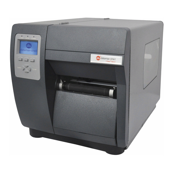
I-Class Mark II Maintenance Manual Overview About the Printer The following drawing highlights the major components of the printer. Cover Assembly Leveling Cam Printhead Latch Printhead Ribbon Take-up Hub Media Sensor Ribbon Supply Hub Platen Media Hub Internal Rewind Media Idler... -
Page 7: Introduction
I-Class Mark II Maintenance Manual Adjustments and Maintenance Introduction This section covers the necessary maintenance and alignment procedures for the printer. Media Sensor Calibration This printer can use many different media compositions, configurations and colors. In addition to adjusting the Media Sensor and selecting the SENSOR TYPE, calibration is required. -
Page 8: Standard Calibration
I-Class Mark II Maintenance Manual Adjustments and Maintenance 2.1.3 Standard Calibration The Standard Calibration can be performed using the NETira CT Utility or using the front panel buttons via the printer’s menu, (see the Operator’s Manual). Standard Calibration provides dynamic readings, which can be helpful when using media with small position-critical notches or marks. - Page 9 I-Class Mark II Maintenance Manual Adjustments and Maintenance Standard Calibration (continued) Step Action Displayed Message Comment Proceed according to the media This sets the paper value, where type: “yyy” represents the current sensor reading. All media except Continuous – Position label material (and liner, if...
-
Page 10: Advanced Entry Calibration
I-Class Mark II Maintenance Manual Adjustments and Maintenance 2.1.4 Advanced Entry Calibration Advanced Entry is an alternate calibration method for special-case media types, where sensor readings are taken using different sampling algorithms and from a list of these readings the best algorithm is selected for manual entry into the database. - Page 11 I-Class Mark II Maintenance Manual Adjustments and Maintenance Advanced Entry Calibration (continued) Step Action Displayed Message Comment Use the UP and DOWN Arrow buttons to set the Gain Number to TRAN SENSOR GAIN This is the Label Value for a gain Record the sensor reading as a setting of 00.
- Page 12 I-Class Mark II Maintenance Manual Adjustments and Maintenance Advanced Entry Calibration (continued) Step Action Displayed Message Comment Raise the printhead assembly then proceed according to the media type: (1) Do not position the Media Die-cut – Remove a label or two Sensor under a perforation;...
- Page 13 I-Class Mark II Maintenance Manual Adjustments and Maintenance Advanced Entry Calibration (continued) Step Action Displayed Message Comment Use the buttons to increment the TRAN SENSOR GAIN These are TOF Values, where Gain Number by one. Record the “yyy” represents the current TOF Value.
- Page 14 I-Class Mark II Maintenance Manual Adjustments and Maintenance Advanced Entry Calibration (continued) Step Action Displayed Message Comment Use the buttons to set the Gain TRAN SENSOR GAIN Number determined in the This example uses Gain Number previous step. Press ENTER to (0 - 31) enable the setting.
- Page 15 I-Class Mark II Maintenance Manual Adjustments and Maintenance Advanced Entry Calibration (continued) Step Action Displayed Message Comment Press the ESC button. Use the buttons to scroll to PAPER SENSOR LEVEL (or if using PAPER SENSOR LEVEL reflective media, REFL PAPER This is the Paper value.
- Page 16 I-Class Mark II Maintenance Manual Adjustments and Maintenance Advanced Entry Calibration (continued) Step Action Displayed Message Comment The printer is ready for use. If the calibration attempt fails, try desensitizing the sensor as follows: Re-enter the ADVANCED MENU. CALIBRATION COMPLETE...
-
Page 17: Printhead Adjustments
I-Class Mark II Maintenance Manual Adjustments and Maintenance Printhead Adjustments To ensure even and consistent print quality across a wide range of media types and sizes, the printhead is adjustable. 2.2.1 Leveling Cam Adjustment The Leveling Cam ensures that even pressure is maintained across the label. Whenever using media that is less than the full width of the platen, proceed as follows: 1. -
Page 18: Pressure Adjustment
I-Class Mark II Maintenance Manual Adjustments and Maintenance 2.2.2 Pressure Adjustment To maintain print quality across the variety of media types, the printhead pressure is adjustable. This adjustment should only be performed, however, after attempting improvement using the HEAT and/or PRINT SPEED settings. -
Page 19: Burn Line Adjustment
I-Class Mark II Maintenance Manual Adjustments and Maintenance 2.2.3 Burn Line Adjustment Note: This adjustment is NOT REQUIRED during a normal printhead replacement. The Burn Line, a row of thermal elements that creates the image, is adjusted to compliance using 6.5-mil (.0065 inch) media to maintain print quality across a majority of types. -
Page 20: Printhead Voltage Adjustment
I-Class Mark II Maintenance Manual Adjustments and Maintenance 2.2.4 Printhead Voltage Adjustment Voltage measurement required; use extreme caution. CAUTION The printhead voltage adjustment is required (1) when replacing the power supply or (2) if the factory voltage setting of the power supply has been changed. No voltage adjustment is required during a routine printhead replacement. - Page 21 I-Class Mark II Maintenance Manual Adjustments and Maintenance NEVER exceed the recommended Printhead Voltage; permanent damage or shortened service life can result. WARNING Printhead Voltage Adjustment Table Printer Printhead Resistance Printhead Voltage Model (ohms) (+/- 0.1 Volt DC) 572 - 597 22.4...
-
Page 22: Ribbon Path Alignment
I-Class Mark II Maintenance Manual Adjustments and Maintenance Ribbon Path Alignment If irregular voids extend intermittently, diagonally through an image printed with ribbon, the cause may be due to ribbon overlap (wrinkling). However, other factors can be involved. Begin troubleshooting by verifying correct adjustment of the Leveling Cam (Section 2.2.1), Printhead Pressure (Section 2.2.2), and Burn Line... - Page 23 I-Class Mark II Maintenance Manual Adjustments and Maintenance 6. Attach the ribbon to the Take-Up Hub. Enter the Quick Test Mode and select 100 Quick Ribbon Test Labels then press TEST to begin printing. Ribbon Take-up Hub Ribbon Printhead Assembly Media 7.
-
Page 24: Maintenance
I-Class Mark II Maintenance Manual Adjustments and Maintenance Maintenance This section details the items, techniques and schedules to help safely and effectively maintain the printer. The following cleaning items are recommended: Isopropyl alcohol • Cotton swabs • A clean, lint-free cloth •... -
Page 25: Cleaning The Printhead
I-Class Mark II Maintenance Manual Adjustments and Maintenance 2.4.1 Cleaning the Printhead NEVER use a sharp object on the Printhead; damage can result. CAUTION If print quality declines (symptoms can include non-compliant bar codes or streaks in the image), the typical cause is debris buildup on the printhead. -
Page 26: Cleaning Card Procedure
I-Class Mark II Maintenance Manual Adjustments and Maintenance 2.4.1.2 Cleaning Card Procedure This cleaning method is recommended when using direct thermal media, thermal transfer media with a wax ribbon, or if symptoms persist after performing the cotton swab procedure (see Section 2.4.1.1). -
Page 27: Cleaning Film Procedure
I-Class Mark II Maintenance Manual Adjustments and Maintenance 2.4.1.3 Cleaning Film Procedure This cleaning method is recommended when using thermal transfer media with a resin ribbon, a HEAT setting of 22 or higher, or if symptoms persist after performing the other cleaning procedures. -
Page 28: Cleaning The Platen
I-Class Mark II Maintenance Manual Adjustments and Maintenance 2.4.2 Cleaning the Platen NEVER use a sharp object on the Platen. CAUTION A Platen contaminated with grit, label adhesive or ink can cause a decline in print quality and, in extreme cases, cause labels to wrap the roller. -
Page 29: Cleaning The Media Path, Media Sensor, And Interior
I-Class Mark II Maintenance Manual Adjustments and Maintenance 2.4.3 Cleaning the Media Path, Media Sensor, and Interior As paper dust and other contaminants accumulate inside the printer, the particles can be pulled through the Media Sensor to the printhead, causing inconsistent label detection and voids in the print. To prevent problems, clean Media Path, Media Sensor and other components as follows: 1. -
Page 30: Cleaning The Ribbon Path
I-Class Mark II Maintenance Manual Adjustments and Maintenance 2.4.4 Cleaning the Ribbon Path If equipped with the Thermal Transfer option, as ink accumulates on the Ribbon Path components, smooth ribbon flow can be impeded causing wrinkling. To prevent problems, clean the Ribbon Path components as follows: 1. -
Page 31: Firmware Updates
When program updates and/or new features are added, they can be downloaded to the printer as follows: 1. Identify the new version for your model of printer from the Datamax-O’Neil Web site at www.datamax-oneil.com and download it onto your computer’s hard drive. -
Page 32: Loading Boot 1 And Boot 2 And Firmware
I-Class Mark II Maintenance Manual Adjustments and Maintenance 2.5.1 Loading Boot 1 and Boot 2 and Firmware 1) Connect the printer to your PC using a serial cable. 2) Launch the NETira CT configuration utility, and query (connect) to the printer, (see the Operator’s Manual for more information on NETira CT). -
Page 33: Troubleshooting
I-Class Mark II Maintenance Manual Troubleshooting Introduction This section covers techniques for isolating and correcting printer problems. Troubleshooting Use the following procedures to isolate and correct malfunctions. When problems are isolated to a Printed Circuit PCB (PCB), assembly replacement is suggested, as component level repair is not generally feasible in the field. -
Page 34: Problem Isolation
I-Class Mark II Maintenance Manual Troubleshooting 3.2.1 Problem Isolation Ensure that AC line voltage is within the operating range for the printer, and that the unit is installed in an acceptable Go to Step 2. environment. Turn ON the Power Switch. Did the printer power up? Go to Section 3.2.2... -
Page 35: No Power
I-Class Mark II Maintenance Manual Troubleshooting 3.2.2 No Power Note: (1) Ensure the AC outlet is functioning properly, with the power cord securely connected to the outlet and printer; and, (2) some printer circuits are protected by resettable fuses, when tripped cycling power will reset those fuses. -
Page 36: No Print
I-Class Mark II Maintenance Manual Troubleshooting 3.2.3 No Print Press TEST. Proceed according to the installed media type: Scroll to PRINT If using direct thermal media: CONFIGURATION, and Possible loose printhead assembly; latch it. then press TEST. • Possible wrong media; ensure type. -
Page 37: Poor Print Quality
I-Class Mark II Maintenance Manual Troubleshooting 3.2.4 Poor Print Quality Note: (1) If printed results are uneven, light or splotchy try increasing HEAT or reducing PRINT SPEED as no further adjustments may be needed; (2) during the procedure below, synthetic media may not produce the intended results due to the requirements of the material;... -
Page 38: Communications Problems
I-Class Mark II Maintenance Manual Troubleshooting 3.2.5 Communications Problems Note: If troubleshooting an Ethernet or USB equipped printer, refer to the documentation that accompanied the option. 1. Turn OFF the printer. Ensure an interface cable is properly Test completed. If the label format does... -
Page 39: Error Resolution
I-Class Mark II Maintenance Manual Troubleshooting Error Resolution All functions are monitored during operation and when a problem is detected a corresponding message will be displayed. (If no message appears, see Section 3.2.) In the tables below locate the Displayed Message, the Description, and then use Solution (listed by probability) to isolate the malfunction. -
Page 40: Fault Messages
I-Class Mark II Maintenance Manual Troubleshooting 3.3.2 Fault Messages Fault Messages receive the highest display priority and, if multiples occur, messages will cycle. Note: To return operation after a fault, correct the condition and then press FEED. Displayed Description... - Page 41 I-Class Mark II Maintenance Manual Troubleshooting Fault Messages (continued) Displayed Description Solution LED Status Message Press any key to continue. Retry the STANDARD CALIBRATION, ensuring that the backing is inserted and the media withdrawn at the appropriate step (see Section 2.1.3).
- Page 42 I-Class Mark II Maintenance Manual Troubleshooting Fault Messages (continued) Displayed Description Solution LED Status Message Press any key to continue. Retry the STANDARD CALIBRATION, ensuring that the reflective mark is inserted facedown during the appropriate step in the procedure (see Section 2.1.3). If this fails, try ADVANCED ENTRY (see Section 2.1.4).
- Page 43 I-Class Mark II Maintenance Manual Troubleshooting Fault Messages (continued) Displayed Description Solution LED Status Message Ensure that ribbon is correctly installed, that the Printhead is latched, that the Leveling Cam is adjusted, and that the printer is calibrated (see the Operator’s Manual).
- Page 44 I-Class Mark II Maintenance Manual Troubleshooting Fault Messages (continued) Displayed Description Solution LED Status Message Press the FEED Key then proceed accordingly: If media moves – 1) The media may be improperly loaded, or calibration may be needed; reload then calibrate (see Section 2.1).
- Page 45 I-Class Mark II Maintenance Manual Troubleshooting Fault Messages (continued) Displayed Description Solution LED Status Message The present sensor (if 1) Remove the label if present. Flashing Yellow Present Sensor equipped) has GREEN: OFF Remove Label detect a label 2) The Present Sensor may be defective; replace.
-
Page 46: Hex Dump Mode
As a final note, many software programs use bit mapping to construct the label making diagnosis difficult. Contact Datamax-O’Neil Technical Support with any questions. To print a Hex Dump, load four-inch wide media (and ribbon, if thermal transfer printing) then proceed according to the type: Turn ON the printer. -
Page 47: Removal And Replacement
I-Class Mark II Maintenance Manual Removal and Replacement Introduction This section details removal and replacement methods for various printer components; where multiple equipment types or options are available, use the procedure that best matches the configuration. Always disconnect AC power before performing service;... - Page 48 I-Class Mark II Maintenance Manual Removal and Replacement 3. Raise the Cover Assembly and loosen the three Screws that secure it to the Centerplate, and then lift the entire Cover Assembly off the printer. Cover Assembly Screws Centerplate Replacement: 1. Lower the Cover Assembly onto the printer.
-
Page 49: Front Panel Fascia
I-Class Mark II Maintenance Manual Removal and Replacement Front Panel Fascia Removal: 1. Turn OFF and unplug the printer. 2. Remove the Cover Assembly (see Section 4.1). 3. Slightly flex the Tabs that extend through notches in the Centerplate and then remove the Front Panel Fascia. -
Page 50: Front Panel Assembly
I-Class Mark II Maintenance Manual Removal and Replacement Front Panel Assembly Removal: 1. Remove the Cover and Front Panel Fascia; see Section 4.1 & 4.2. 2. Remove the two Screws that secure the Front Panel Assembly to the Centerplate then disconnect the Front Panel Cable and remove the Front Panel Assembly from the printer. -
Page 51: Platen
I-Class Mark II Maintenance Manual Removal and Replacement Platen Removal: 1. Turn OFF and unplug the printer. 2. Raise the cover and remove the Tearplate Fascia, Thumbscrew, and Tearplate. 3. Remove the Gear Cover by pulling the far side out then away from the Centerplate. - Page 52 I-Class Mark II Maintenance Manual Removal and Replacement 4. Remove the two Screws that secure the Bearing Plate and then remove the Bearing Plate from the Platen Block. Bearing Plate Screws 5. Remove the Platen Assembly from the Platen Block. Pivot...
-
Page 53: Platen Block
I-Class Mark II Maintenance Manual Removal and Replacement Platen Block Removal: 1. Turn OFF and unplug the printer. 2. Remove the Cover and Platen; see Section 4.1 & 4.4 3. Remove the three Screws securing the Platen Block to the Centerplate. Slide the Platen Block out of the printer. -
Page 54: Printhead
I-Class Mark II Maintenance Manual Removal and Replacement Printhead Use extreme care when handling the printhead. CAUTION Removal: 1. Turn OFF and unplug the printer. 2. Raise the cover. With the Printhead Assembly lowered, loosen the Printhead Mounting Screw (it will remain in the assembly). - Page 55 I-Class Mark II Maintenance Manual Removal and Replacement Replacement: 1. Carefully reconnect both cables to the Printhead. 2. Position the Printhead onto the Locating Pins in the Printhead Assembly. Printhead Assembly Locating Pins Printhead Cables Printhead 3. Secure the Printhead to the Printhead Assembly with the Printhead Mounting Screw, but do NOT over- tighten.
-
Page 56: Printhead Assembly
I-Class Mark II Maintenance Manual Removal and Replacement Printhead Assembly Removal: 1. Turn OFF and unplug the printer. 2. Remove the Printhead; see Section 4.4. 3. Remove the two Screws that secure the End Cap to the Extrusion. 4. While supporting the Printhead Assembly, remove the End Cap, Wavy Washer, and Bushings, (note Bushings may remain captive in the End Cap. - Page 57 I-Class Mark II Maintenance Manual Removal and Replacement Replacement: 1. Place the Head Lift Spring onto the Printhead Assembly Boss; situate the Short Leg behind the Tab. Printhead Assembly Boss Head Lift Spring Short Leg 2. Rotate the Long Leg of the Head Lift Spring downward, loading it against the Extrusion, and then insert the Printhead Boss into the Centerplate bushing.
-
Page 58: Printhead Assembly Breakdown
4.7.1 Printhead Assembly Breakdown Within the Printhead Assembly, there are several serviceable parts and sub-assemblies. The following section is an overview of the breakdown of the Printhead Assembly, refer to the I-Class Mark II Parts Catalog for available parts. Removal: 1. - Page 59 I-Class Mark II Maintenance Manual Removal and Replacement 4. Carefully separate the Lower Carriage from the Printhead Assembly, compressing the spring-loaded assembly as necessary to separate the parts, and then remove the Alignment Springs. Alignment Springs Printhead Assembly Lower Carriage 5.
- Page 60 I-Class Mark II Maintenance Manual Removal and Replacement Replacement: 1. Place the Pressure Springs and the Alignment Springs into the sockets of the Middle Carriage and place the Cams into the socket holes of the Upper Carriage then orient the Cam Indicators for least pressure (see below).
-
Page 61: Media Sensor
I-Class Mark II Maintenance Manual Removal and Replacement Media Sensor Removal: 1. Turn OFF and unplug the printer. 2. Remove the Cover Assembly; see Section 4.1. 3. Disconnect the Media Sensor cable and remove the Screw that secures the Media Sensor Guide to the Post. -
Page 62: Main Logic Pcb
I-Class Mark II Maintenance Manual Removal and Replacement Main Logic PCB Removal: 1. Turn OFF and unplug the printer. Remove the Cover Assembly (see Section 4.1). 2. Disconnect the interface cable(s) from the Main Logic PCB. 3. Remove the four Screws on the rear of the printer that secure the Main Logic PCB. -
Page 63: Fuses
I-Class Mark II Maintenance Manual Removal and Replacement 4.10 Fuses Only use a replacement fuse with the rating and type as the original fuse; failure to comply could cause serious damage, including fire. Use caution when replacing Fuse F1, as this fuse will only blow during a failure in CAUTION the primary switching circuit and may indicate a more serious electrical problem. -
Page 64: Power Supply Pcb
I-Class Mark II Maintenance Manual Removal and Replacement 4.11 Power Supply PCB Removal: 1. Turn OFF and unplug the printer. 2. Remove the Cover Assembly; see Section 4.1. 3. Disconnect the cables from the Power Supply PCB. 4. Remove the two Screws and Nut Plate that secure the AC Connector. - Page 65 I-Class Mark II Maintenance Manual Removal and Replacement Replacement: 1. Position the Power Supply PCB in the printer then secure it with the four Screws. 2. Place the Washer onto the Screw, and then secure the Ground Wire Lug to the chassis with the Screw.
-
Page 66: Drive Motor Assembly
I-Class Mark II Maintenance Manual Removal and Replacement 4.12 Drive Motor Assembly Note: Though the illustration depicts the motor replacement of a 203DPI model, except as detailed below the procedure is the same for 300/600DPI. Removal: 1. Turn OFF and unplug the printer. - Page 67 I-Class Mark II Maintenance Manual Removal and Replacement Replacement: 1. Depending upon the resolution of the printer, position the Isolator against the Centerplate Standoffs then secure it with the two Screws. Isolator Centerplate Standoffs (203 DPI) Screws Centerplate Standoffs Isolator...
-
Page 68: Media Supply Hub
I-Class Mark II Maintenance Manual Removal and Replacement 4.13 Media Supply Hub Removal: 1. Turn OFF and unplug the printer. 2. Remove the Cover Assembly; see Section 4.1. 3. Remove the Power Supply PCB; see Section 4.11. 4. Remove the Screw securing the Media Hub Assembly to the Printer. -
Page 69: Thermal Transfer Assembly
I-Class Mark II Maintenance Manual Removal and Replacement 4.14 Thermal Transfer Assembly Removal: 1. Turn OFF and unplug the printer. Raise the cover. 2. Remove the three Screws that secure the Thermal Transfer Assembly and then remove the assembly from the Centerplate. -
Page 70: 4.14.1 Ribbon Supply Hub
I-Class Mark II Maintenance Manual Removal and Replacement 4.14.1 Ribbon Supply Hub Removal: 1. Remove the Thermal Transfer Assembly; see Section 4.14. 2. Remove the Screw and Metal Washer that secures the Ribbon Supply Hub to the Housing. 3. Remove the Ribbon Supply Hub and Nylon Washer from the Housing. - Page 71 I-Class Mark II Maintenance Manual Removal and Replacement 3. Rotate the Ribbon Supply Hub until the Pin engages the Notch in the Housing. Housing Ribbon Supply Hub Nylon Washer Notch 4. Secure the Ribbon Supply Hub to the Housing with the Metal Washer and Screw.
-
Page 72: 4.14.2 Ribbon Take-Up Hub & Clutch Assembly
I-Class Mark II Maintenance Manual Removal and Replacement 4.14.2 Ribbon Take-up Hub & Clutch Assembly Removal: 1. Remove the Thermal Transfer Assembly; see Section 4.14. 2. Remove the E-Ring from the Take-Up Hub shaft and then remove the Inner Bearing. -
Page 73: Rewind Assembly
I-Class Mark II Maintenance Manual Removal and Replacement 4.15 Rewind Assembly Removal: 1. Turn OFF and unplug the printer. Raise the cover. 2. Remove the three Screws that secure the Rewind Assembly to the Centerplate then remove the Rewind Assembly. -
Page 74: 4.15.1 Rewind Hub, Clutch Assembly, And Spur Gear
I-Class Mark II Maintenance Manual Removal and Replacement 4.15.1 Rewind Hub, Clutch Assembly, and Spur Gear Removal: 1. Remove the Rewind Assembly; see Section 4.15. 2. Remove the E-Ring from the Rewind Hub shaft and remove the Inner Bearing. 3. Remove the Rewind Hub and the Outer Bearing from the Rewind Housing.