Datamax I-Class Mark II Operator's Manual
Hide thumbs
Also See for I-Class Mark II:
- Operator's manual (96 pages) ,
- Maintenance manual (74 pages) ,
- Installation and use manual (12 pages)
Table of Contents
Advertisement
Quick Links
Advertisement
Table of Contents

Related Manuals for Datamax I-Class Mark II


Summary of Contents for Datamax I-Class Mark II
- Page 1 Operator’s Manual...
-
Page 3: Limitation Of Liability
Datamax-O’Neil hereunder by the purchaser for a defective product. In no event shall Datamax-O’Neil be liable to the purchaser for any damages resulting from or related to any failure or delay of Datamax-O’Neil in the delivery or installation of the computer hardware, supplies or software or in the performance of any services. - Page 4 Agency Compliance and Approvals UL60950-1; 2 Edition CSA C22.2 No. 60950-1-07 2 Edition The manufacturer declares under sole responsibility that this product conforms to the following standards or other normative documents: EMC: EN 55022 (2006) Class A EN 50024 (1998) + A1:2001; +A2:2003 Safety: This product complies with the requirements of IEC 60950-1, 2 Edition, 2005-12 ROHS: 2002/95/EC...
-
Page 5: Table Of Contents
Getting Started Introduction ................1 Unpacking................1 Printer Setup Printer Connections ..............3 2.1.1 Power Connection ............3 2.1.2 Interface Connection ............ 4 Loading Media ................ 5 Media Sensor Adjustment ............7 Loading Ribbon ............... 8 OPTImedia ................11 Internal Rewinder..............12 Printer Operation Front Panel................ -
Page 6: Table Of Contents
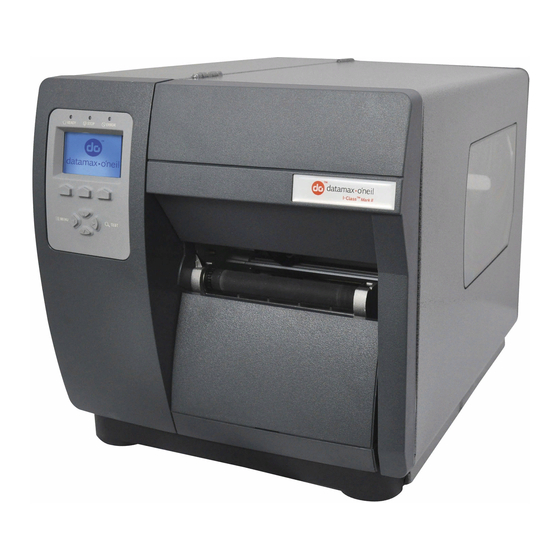
Maintenance and Adjustments Cleaning Intervals ..............57 Cleaning the Printhead ............. 58 Media Width Adjustment ............60 Printhead Pressure Adjustment ..........61 Printhead Replacement ............62 Resetting the Printer..............63 Upgrading Firmware ..............63 Troubleshooting Problem Resolution..............65 Hex Dump Mode ..............69 Appendix A - Specifications Appendix B - Wireless and Wired LAN Setup Network Card Setup .............. - Page 7 Congratulations on your I-Class Mark II printer purchase. The I-Class Mark II printer family, hereafter referred to as ‘the printer’, blends the rugged durability of die-cast construction with state-of-the-art electronics and user-friendly features to redefine the standard in industrial thermal printers.
- Page 8 Chapter 1 – Getting Started...
-
Page 9: Power Connection
2.1.1 Power Connection Before connecting the AC Power Cord or interface cables to the printer, ensure the Power On/Off Switch is in the ‘Off’ position. Place the printer on a firm, level surface. Ensure that the Power Switch on the Printer is in the ‘Off’ position. Connect the AC Power Cord to the receptacle on the back of the Printer, and then plug the AC Power Cord into a properly grounded outlet. -
Page 10: Interface Connection
2.1.2 Interface Connection The printer can be connected to the host via the parallel, USB, serial, or optional network interface. The printer will automatically connect to the first port that delivers valid data. Once established, the printer’s power must be cycled ‘Off’... - Page 11 Load media into the printer as follows: 1. Open the media cover. Rotate and unlock the Printhead Latch and raise the Printhead Assembly. 2. Rotate the Media Guide down. Printhead Latch Printhead Assembly Media Guide 3. Slide the Roll Media onto the Media Hub. 4.
- Page 12 5. Close the Printhead Assembly and rotate the Printhead Latch to the locked position. 6. Close the cover and press the FEED button several times to position the media and ensure proper tracking. Printhead Assembly Printhead Latch If the printer does not correctly sense the top of each label, it may be necessary to calibrate the printer (see Section 3.4 Media Calibration).
- Page 13 The Media Sensor needs to be positioned so that the printer can detect the presence of media and the top-of-form (except for continuous stock, where the TOF is set through the front panel). To adjust: 1. With media loaded, as described in Section 2.2, grasp the Slide Tab and move the Sensor Eye Mark into position over media according to the table below.
- Page 14 Ribbon is required with thermal transfer media. It is recommended that the width of the ribbon be slightly wider than the media being used. The printer can use either ribbons with the ‘coating side in’ or ribbons with the ‘coating side out’. To load: Using a ribbon that is slightly wider than your media (and liner, if any) will help protect against •...
- Page 15 Ribbon Routing Diagrams (CSI) ‘Coating Side In’ Ribbon Routing (CSO) ‘Coating Side Out’ Ribbon Routing Chapter 2 - Printer Setup...
- Page 16 3. Route the ribbon under the Ribbon Idler and then out the front of the printer approximately 12 inches as shown. Ribbon Roll Ribbon Supply Hub Ribbon Idler 4. Close the Printhead Assembly and rotate the Printhead Latch to the locked position. Route the ribbon up and then around to the Ribbon Take-Up Hub, winding it several times in a clockwise direction to secure it in place.
-
Page 17: Optimedia
The OPTIMedia function is designed to reduce set up time when using Datamax-O’Neil branded media and ribbons. This feature enables the printer to automatically adjust print heat and print speed settings to optimum levels to produce the best possible print quality. By using the model number prefix of the media and ribbon (printed on the shipping box), the printer can be quickly configured to produce optimum print quality for that particular media and ribbon combination. -
Page 18: Internal Rewinder
When equipped with the Internal Rewind option, labels can be rewound or, with the addition of a Peel and Present option, dispensed automatically for application. If equipped, follow the instructions below to begin using the Internal Rewinder: 1. Press down then pull outward to remove the Front Fascia. 2. - Page 19 4. Load media as described in section 2.2. Feed approximately 20 inches (50 cm) of media out of the printer. Route the media over the Arc Plate and then back into the printer and around the Rewinder Hub. Arc Plate ...
- Page 20 Chapter 2 - Printer Setup...
- Page 21 The Control Panel is an event-driven interface composed of a graphic display and keypad. In addition to providing current printer information, the mode-dependent panel allows the items in the main display area and the key functions to change as operational events require. Ready/Receiving Data ...
- Page 22 3.1.1 Display Icons Display Icon Description Initialization, typically brief (but a damaged or invalid printhead can delay the process). Display large fonts Input Mode – DPL Input Mode – LINE LINE Input Mode – PL-Z PL Z Input Mode – AUTO SD memory card detected.
-
Page 23: Front Panel
The Windows driver is located on the Accessories CD-Rom included with your printer. For the latest version please visit our web site at www.datamax-oneil.com. Be sure your printer’s firmware version is 10.03_0016B or greater. Firmware is available from our website, for the latest version please visit our web site at http://www.datamax-oneil.com... -
Page 24: Important Notes
Important Notes: The Windows driver functions the same as any other Windows printer. A built in help file is available for complete information on all settings; however, there are some important settings that should be observed for trouble free printing. Page Setup Tab: Stock Options Tab: Print Speed &... - Page 25 printer. Older versions might not operate correctly with some printers. For the latest version please visit our web site at http://www.datamax-oneil.com Be sure your printer’s firmware version is 10.03_0016B or greater. Firmware is available from our website, for the latest version please visit our web site at http://www.datamax-oneil.com...
- Page 26 NETira CT Usage 1) Once installed launch the NETira CT configuration utility: 2) Be sure the printer is ‘ON’. Connect the host to the printer (see Section 2.1.2). For Serial Connections: a) Query the printer by using the ‘Auto Detect’ button. This will connect to the printer and retrieve the setting currently stored in the printer.
- Page 27 3) At this point you may browse the Printer Component categories and make any changes necessary to the printer configuration. 4) Once complete, send the new settings to the printer using the ‘Send’ button. Note: When sending the changes to the printer, only the changes displayed on the current page will be sent.
-
Page 28: Quick Calibration
3.4.1 Quick Calibration Quick Calibration should be performed as part of the media loading routine to fine-tune the sensing parameters. (1) This calibration is not necessary when using continuous stock. (2) Media containing large gaps may require a change in the PAPER EMPTY DISTANCE before proceeding. -
Page 29: Standard Calibration
3.4.3 Standard Calibration The Standard Calibration can be performed using the NETira CT Utility (see Section 3.3) or using the front panel buttons via the printer’s menu, see Section 4.5. Standard Calibration provides dynamic readings, which can be helpful when using media with small position-critical notches or marks. - Page 30 Standard Calibration (continued) Step Action Displayed Message Comment Proceed according to the media This sets the paper value, where type: “yyy” represents the current sensor reading. All media except Continuous – Position label material (and liner, if SCAN PAPER (1) If using preprinted media, any) over the sensor then press ensure that the area placed over the ESC Key.
-
Page 31: Media Calibration
3.4.4 Advanced Entry Calibration Advanced Entry is an alternate calibration method for special-case media types, where sensor readings are taken using different sampling algorithms and from a list of these readings the best algorithm is selected for manual entry into the database. ... - Page 32 Advanced Entry Calibration (continued) Step Action Displayed Message Comment Use the UP and DOWN Arrow buttons to set the Gain Number to TRAN SENSOR GAIN This is the Label Value for a gain Record the sensor reading as a setting of 00. Label Value for Gain Number 00 in (0 - 31) a table (32 rows by four columns,...
- Page 33 Advanced Entry Calibration (continued) Step Action Displayed Message Comment Raise the printhead assembly then proceed according to the media type: (1) Do not position the Media Die-cut – Remove a label or two Sensor under a perforation; and from the liner then position the if using preprinted media, ensure TRAN SENSOR GAIN liner in the Media Sensor.
- Page 34 Advanced Entry Calibration (continued) Step Action Displayed Message Comment Use the buttons to increment the TRAN SENSOR GAIN These are TOF Values, where Gain Number by one. Record the “yyy” represents the current TOF Value. Repeat this process for (0 - 31) sensor reading.
- Page 35 Advanced Entry Calibration (continued) Step Action Displayed Message Comment Use the buttons to set the Gain TRAN SENSOR GAIN Number determined in the This example uses Gain Number previous step. Press ENTER to (0 - 31) enable the setting. Complete a table (see example below) using new measurements, as follows: (A) Raise the Printhead Assembly.
- Page 36 Advanced Entry Calibration (continued) Step Action Displayed Message Comment Press the ESC Key. Use the buttons to scroll to PAPER SENSOR LEVEL (or if using PAPER SENSOR LEVEL reflective media, REFL PAPER This is the Paper value. LEVEL) and then press ENTER. (0 - 255) Use the buttons to set the Paper value determined in Step M and...
- Page 37 Advanced Entry Calibration (continued) Step Action Displayed Message Comment The printer is ready for use. If the calibration attempt fails, try desensitizing the sensor as follows: Re-enter the ADVANCED MENU. CALIBRATION COMPLETE Go to MEDIA SETTINGS / Press and hold the FEED Key until SENSOR CALIBRATION / Followed by...
- Page 38 Chapter 3 - Printer Operation...
-
Page 39: The User Menu
The Menu System contains three primary branches, each with a differing level of access to secondary menus or functions: The User Menu accesses basic printer settings and functions; The Advanced Menu accesses all operational settings, functions, and diagnostics; and, ... - Page 40 The User Menu contains basic selections in these menus: Media Settings Print Control Printer Options System Settings (1) Some setting changes will only become effective (and saved) after selecting YES at the Save Changes prompt. (2) Labeling software may, in some cases, override the printer menu settings;...
-
Page 41: User-Defined Label
The Test Menu contains test and informational label selections: Print Quality Label Print Configuration Ribbon Test Label Test Label Validation Label Print Last Label User Defined Label Internally generated, these labels are printed at pre-selected media type, speed, and heat settings. - Page 42 DISPLAYED ITEM ITEM DESCRIPTION OPTimedia Automatically configures various print settings to the selected media/ribbon combination. MEDIA TYPE Selects the method used to print labels and should be set according to the type of media being used, where: DIRECT THERMAL Sets use for media that is heat reactive to produce an image. THERMAL Sets use for media that requires a ribbon to produce an image.
- Page 43 DISPLAYED ITEM ITEM DESCRIPTION SENSOR Selects the media sensor calibration method, where: CALIBRATION PERFORM Sets the values via internal printer calculations, as described in the STANDARD CALIBRATION CALIBRATION procedure. ADVANCED ENTRY Sets the values via manual entry (typically for hard to calibrate label stocks), as described in the ADVANCED ENTRY CALIBRATION where: PAPER SENSOR Establishes the threshold for the paper value (0 - 255), where 170 is the default...
-
Page 44: Print Control
Print Control The Print Control menu contains printing throughput, offset and custom setup functions: Heat Print Speed Feed Speed Reverse Speed* Slew Speed* Row Offset Column Offset Present Distance TOF Precedence* Custom Adjustments* ... - Page 45 DISPLAYED ITEM ITEM DESCRIPTION PRESENT DISTANCE Sets the label stop position (0 - 4.00 inches) past the start of print position upon output. When subsequent label formats are received, the printer will automatically back up the label to position it at the start of print position, where: 0.00 in.
-
Page 46: Printer Options
Printer Options The Printer Options menu contains file-handling, module, and optional equipment settings: Modules Present Sensor Cutter GPIO Port The menu selections are defined as follows: DISPLAYED ITEM ITEM DESCRIPTION MODULES Controls memory handling functions, where: DIRECTORY Allows viewing and printing of the available space and file types (including plug-in files) present on a module. - Page 47 DISPLAYED ITEM ITEM DESCRIPTION CUTTER Controls the Cutter operation, where: MODE Sets the detection method and response of the printer: AUTO Is the default setting, where the presence of the cutter option is automatically sensed. If detected, the cutter is enabled; otherwise, it will be ignored. ENABLED Enables the cutter.
-
Page 48: System Settings
RIBBON LOW Sets the type of output signal generated to indicate Ribbon Low condition where: ACTIVE LOW Outputs a logic low upon condition. ACTIVE HIGH Outputs a logic high upon condition.. SLEW ENABLE Selects the type of input signal required to initiate label slew, where: STANDARD Triggers slew with a low signal. - Page 49 DISPLAYED ITEM ITEM DESCRIPTION CONFIGURATION Controls the creation, storage, and recall of printer configuration files, where: FILE RESTORE AS Returns the printer to a previously saved configuration. CURRENT SAVE SETTING Creates a file based on the current printer configuration, as described here. DELETE FILE Removes a selected configuration file from memory.
- Page 50 DISPLAYED ITEM ITEM DESCRIPTION DOUBLE BYTE Selects the optional ILPC code page used to print double byte fonts, where: SYMBOLS Japanese Industry Standard SHIFT JIS Shift Japanese Industry Standard Extended UNIX Code UNICODE Unicode (including Korean). Default setting. Government Bureau Industry Standard; Chinese (PRC) BIG 5 Taiwan encoded ...
- Page 51 DISPLAYED ITEM ITEM DESCRIPTION SET FACTORY Returns the printer settings to the factory-programmed values (except CUSTOM DEFAULTS ADJUSTMENTS and calibrations); or, if selected, to the Factory Setting File, where selecting YES at the prompt causes the configuration to be restored. FORMAT Defines the manner in which overlapping text and graphics appear when printed, ATTRIBUTES...
- Page 52 DISPLAYED ITEM ITEM DESCRIPTION UNITS OF MEASURE Sets the measurement standard used, where: IMPERIAL Uses inches. (Default Setting) METRIC Uses millimeters and centimeters. INPUT MODE Defines the type of processing that will occur when data is received, where: PL-Z Alternative programming language processing will be used, with the exception of the following DPL specific-parameters: DPL Emulation;...
- Page 53 DISPLAYED ITEM ITEM DESCRIPTION ROW EMULATION Allows the row dots per inch to be adjusted (103 - 303), so that numbers smaller than the printhead resolution enlarge the height of the printed output and numbers larger reduce it, where: XXX Dots SOP EMULATION Allows label positioning commands to function with backward compatibility when printing label formats designed for legacy models, where:...
- Page 54 DISPLAYED ITEM ITEM DESCRIPTION FAULT HANDLING Determines the intervention required and the disposition of the label in process when a fault occurs, where: LEVEL Selects the user action and the reprint status upon declaration of a fault, where: NO REPRINT Printing stops and a fault message is displayed.
- Page 55 Communications The Communications menu contains interface and host control functions: Serial Port A* Parallel Port A* USB Port* Network Interface* Host Settings* Items denoted with an asterisk (*) are only accessible through the Advanced Menu. The menu selections are defined as follows: DISPLAYED ITEM ITEM DESCRIPTION...
- Page 56 DISPLAYED ITEM ITEM DESCRIPTION GENERIC Controls global communication settings shared by wired and wireless LAN SETTINGS ACTIVE Selects the network interface currently in use by the printer, where: INTERFACE NONE Disables both interfaces WIRED Selects the Wired Ethernet interface ETHERNET WIRELESS Selects the Wireless Ethernet interface ETHERNET...
- Page 57 DISPLAYED ITEM ITEM DESCRIPTION WIRED Controls the communications settings for the wired Ethernet network interface ETHERNET Sets the address discovery method, where: DISCOVERY USE STATIC The stored static IP, Subnet Mask, and / or Gateway Address will be used. ADDRESSES USE DHCP The card broadcasts over the network using DHCP protocol to receive addresses from the responsible server at startup.
- Page 58 DISPLAYED ITEM ITEM DESCRIPTION TCP PRINT Selects the Port to use for all TCP network communications; Default is 9100 PORT INACTIVITY Set the amount of time (in seconds) in which the current port will remain open TIME when no activity is present. LPD PRINT Selects the Port to use for all LPD network communications;...
- Page 59 DISPLAYED ITEM ITEM DESCRIPTION CONTROL Allows changes to the prefix of the software commands interpreted by the printer, CODES where: STANDARD Use these characters: Hex 01 = SOH command; Hex 02 = STX command; count- CODES by = ^; Hex 1B = ESC; Hex 0x0D = Carriage Return. (Default Setting) ALTERNATE Use these characters: Hex 5E = SOH command;...
- Page 60 Diagnostics The Diagnostics menu contains testing functions and printhead reporting selections: Hex Dump Mode* Options Testing* Print Test Rate (min)* Sensor Readings* Ribbon Sensor Limits* iPH Report* Flash Module Report* Items denoted with an asterisk (*) are only accessible through the Advanced Menu. The menu selections are defined as follows: DISPLAYED ITEM ITEM DESCRIPTION...
- Page 61 DISPLAYED ITEM ITEM DESCRIPTION SENSOR READINGS Displays the values (0 – 255) from the printer sensors, where: TRAN RIBM RANK THR = Printhead thermistor sensor; TRAN = Gap media sensor (REFL when set to reflective); RIBM = Ribbon sensor; 24V = 24 volt power supply sensor; PS = Present sensor;...
- Page 62 Chapter 4 – Menu System...
-
Page 63: Cleaning The Printhead
Isopropyl alcohol is a flammable solvent; always take the proper precautions when using this substance. Proper cleaning is critical. To maintain peak performance of the printer, Datamax-O’Neil offers a complete line of cleaning products including pens, cards, films and swabs. Visit our website at http://www.datamax-oneil.com to learn more. - Page 64 If print quality declines (symptoms include non-compliant bar codes, print dropouts, and streaks; see sample label below), the typical cause is debris build-up on the printhead. Furthermore, when the build-up is not removed it may lead to element failure, greatly reducing the service life of the printhead.
-
Page 65: Media Width Adjustment
Automated Printhead Cleaning 1. Remove media and ribbon. 2. Place a Datamax-O’Neil Cleaning Card, part number 70-2013-01 under the printhead. Lower and lock the printhead. Ensure that the Media Width Adjustment is not engaged. 3. Press and hold the TEST Key for approximately four seconds. - Page 66 Whenever using narrow media (sizes that are less than the width of the printhead), adjust the Leveling Cam for even pressure distribution. Adjust the Printhead Leveling Cam as follows: 1. With media loaded, download your label format (or use a Test Menu format) then begin printing a small batch of labels.
-
Page 67: Printhead Pressure Adjustment
Printhead Pressure Adjustment should only be performed after attempting to improve print quality through the use of other print quality controls. A. With media loaded, download your label format (or use a Test Menu format) then begin printing a small batch of labels. B. - Page 68 Printheads are fragile; use extreme care when handling and never use a sharp object on the surface. If you have questions, contact a qualified technician or Datamax-O’Neil Technical Support before proceeding. 1. Touch a bare metal part of the printer’s frame to discharge any static electricity that may be present on your body.
- Page 69 When program updates and/or new features are added, they can be downloaded to the printer as follows: 1) Identify the new version for your model of printer from the Datamax-O’Neil Web site at www.datamax-oneil.com and download it onto your computer’s hard drive.
- Page 70 Loading Boot 1 and Boot 2 and Firmware 1) Connect the printer to your PC using a serial cable 2) Launch the NETira CT configuration utility, and query (connect) to the printer, (see section 3.3 for more information on NETira CT). It is recommended that the configuration be saved before downloading firmware, and restored ...
-
Page 71: Hex Dump Mode
Should a problem arise, the information in this section will help you resolve it. The following table lists problems that may not necessarily generate an error condition. Items denoted with an asterisk (*) are only for display-equipped printers. Try this solution… If experiencing this problem…... - Page 72 Try this solution… If experiencing this problem… Check the label format for character placement outside the dimensions of the label; all row/column values must allow enough space for the height/length of the characters and bar codes to be printed within the format size. The available memory may have been exceeded by the Missing information in the printed memory requirement of the label format.
- Page 73 Try this solution… If experiencing this problem… Examine the used ribbon for an image: If there is an image on the used ribbon: Verify that the ribbon was properly loaded per Section 2.4. If properly loaded, the wrong coating configuration was used.
- Page 74 Try this solution… If experiencing this problem… The printhead may need cleaning; see Section 5.2. Adjust the Heat and Print Speed settings through the Front Panel or by host commands, see Section 4.5.) The media/ribbon combination may not be compatible; Poor print quality: contact a Media Representative.
- Page 75 The figure below is a sample Hex Dump Label. After sending a label format to the printer, the hex code output will be immediate. As a final note, many software programs use bit mapping to construct the label, making diagnosis difficult. Contact Datamax-O’Neil Technical Support with any questions.
- Page 76 Chapter 6 – Troubleshooting...
- Page 77 Mechanical Width 12.62 inches (320.6 mm) Depth 18.60 inches (472.5 mm) Height 12.70 inches (322.6 mm) Weight 45 pounds (20.5 kg) Operating Temperature 32 F to 100 F (0 C to 38 C) Humidity 95% non-condensing AC Input Voltage 90 – 132 or 180 – 264 VAC @ 47–63 Hz, auto-ranging. Printing Print Method Direct Thermal;...
- Page 78 Media/Ribbon Media Types Roll-Fed, Die-Cut, Continuous, Fan-Fold Max. Media Width 4.65" (118 mm) Min. Media Width 1.0" (25 mm) Max. Print Width 4.10” (104.0 mm): I-4212e 4.16” (105.7 mm): I-4310e & I-4606e Print Length Range .25 - 99" (6 - 2475 mm); with Cutter min. 1.25” (31.8mm); with peel and Present min.
- Page 79 Approved Media To achieve optimum print quality and maximum printhead life, Datamax-O’Neil specifies the use of Datamax-O’Neil brand media and ribbons. These supplies are specially formulated for use in our printers; use of non-Datamax-O’Neil supplies may affect the print quality, performance, and life of the printer or its components.
- Page 80 Appendix A – Specifications...
- Page 81 Whether a wired or wireless connection is intended, it is recommend to establish a wired connection to the printer first. This will allow access to the printers internal web pages to configure the settings necessary for a typical wireless connection. If a wired connection is not or can not be achieved all connection parameters can also be set using the NETira CT configuration utility, see section 3.3.
- Page 82 1. Open your web browser. Type in the IP Address assigned to the printer. The printers default IP address is: 192.168.10.26. If a different IP Address has been assigned to the printer, make sure to enter the correct IP address. The following page will appear: The printer’s internal web pages are divided into 10 pages that are accessible via the...
-
Page 83: B.2.1 Wireless Setup – Infrastructure
B.2.1 Wireless Setup – Infrastructure After a successful setup is made via a wired connection, the Wireless connection (if equipped) can now be configured in infrastructure mode using a static or DHCP issued IP address. 1. Open your web browser. Type in the IP Address of the printer. -
Page 84: B.2.1 Wireless Setup – Ad-Hoc
Once the printer has restarted the icon will be displayed signifying that an IP address has been obtained. Allow up to 90 seconds for the printer to retrieve an IP address. At this point it is recommended to print a Network Report. This Network Report is generated by the printer and lists important default information such as the IP and MAC Addresses as well as SSID for wireless connections. - Page 85 4. In the SSID field type the name of the SSID you wish to assign to the printer. 5. Under the “WIFI Security and Authentication”, set any security/authentication settings necessary for your network. 6. Scroll down to the bottom of the page, enter the password (default is “sysadm”) and click Apply.
- Page 86 The following screen shots are taken from Windows 2000, other Windows versions will be similar. Start the Windows Make sure that “Add Printer Wizard”. ‘Local Printer’ is The following screen selected and then should appear, click click ‘Next’. ‘Next>’. Select on ‘Create a Click ‘Next’.
- Page 87 Insert the Accessories Browse to the CD-Rom and click “\DRIVERS\Seagull” ‘Browse’. folder on the CD- ROM, make sure the file “for 95, 98, me, 2000, and xp.inf” is selected and click ‘OK’. Click ‘OK’. Choose your printer from the list and then click ‘Next’.
- Page 88 Appendix B – Wireless and Wired LAN Setup...
- Page 89 Different languages and / or Datamax-O’Neil-provided translations can be downloaded to replace the standard (English) menu of the printer by changing the spreadsheet that defines the system dictionary. To change the language you will add a new language column (or modify the existing column) in the spreadsheet, click on the “Generate DPL file(s)”...
- Page 90 B. Click the “Enable Macro” box. The following screen appears: C. Click on Column J and enter the new language, or modify an existing one. Some tips on this process: Message Size – When entering new messages, reference the “MAX” column: this is the •...
- Page 91 An error has occurred if the printer displays the new language selection, but all messages remain in English. In this case, re-check your process or contact Datamax-O’Neil Technical Support (be ready to provide the Common.xls and DPL download files created). Other error...
- Page 92 To restore the factory generated EFIGS image, download the file *832296.01A to the printer. • This file is located on the Datamax-O’Neil FTP site. The letter at the end of the file name (e.g., A) specifies the revision. The latest revision will be available on the FTP site.
- Page 93 The screen shot below is an example of Unicode defined languages, Chinese & Russian. Note the only additional information required is the “double” in row 1. Appendix C – Menu Language...