Endress+Hauser Micropilot FMR10 Operating Instructions Manual
Free space radar
Hide thumbs
Also See for Micropilot FMR10:
- Operating instructions manual (72 pages) ,
- Technical information (44 pages) ,
- Brief operating instructions (28 pages)

Related Manuals for Endress+Hauser Micropilot FMR10


Summary of Contents for Endress+Hauser Micropilot FMR10
-
Page 1: Administration
BA01577F/00/EN/01.16 Products Solutions Services 71325111 Operating Instructions Micropilot FMR10 Free space radar... -
Page 2: Administration
Order code: XXXXX-XXXXXX Ser. no.: XXXXXXXXXXXX Ext. ord. cd.: XXX.XXXX.XX Serial number www.endress.com/deviceviewer Endress+Hauser Operations App A0023555 Endress+Hauser... -
Page 3: Table Of Contents
6.1.1 Micropilot FMR10 ....10 Maintenance ..... . 32 13.1 Exterior cleaning . -
Page 4: Document Information
Document information Micropilot FMR10 Document information Symbols for certain types of information Symbol Meaning Permitted Procedures, processes or actions that are permitted. Preferred Procedures, processes or actions that are preferred. Forbidden Procedures, processes or actions that are forbidden. Indicates additional information. -
Page 5: Terms And Abbreviations
Micropilot FMR10 Terms and abbreviations Symbol Meaning Hazardous area Indicates a hazardous area. Safe area (non-hazardous area) Indicates the non-hazardous area. Terms and abbreviations Term/abbreviation Explanation Document type "Operating Instructions" Document type "Brief Operating Instructions" Technical Information Document type "Special Documentation"... -
Page 6: Basic Safety Instructions
The manufacturer is not liable for damage caused by improper or non-designated use. Verification for borderline cases: ‣ For special fluids and fluids for cleaning, Endress+Hauser is glad to provide assistance in verifying the corrosion resistance of fluid-wetted materials, but does not accept any warranty or liability. -
Page 7: Workplace Safety
Registered trademarks The Bluetooth® word mark and logos are registered trademarks owned by the Bluetooth SIG, Inc. and any use of such marks by Endress+Hauser is under license. Other trademarks and trade names are those of their respective owners.” Apple®... - Page 8 Registered trademarks Micropilot FMR10 Android® Android, Google Play and the Google Play logo are trademarks of Google Inc. Endress+Hauser...
-
Page 9: Supplementary Documentation
Micropilot FMR10 Supplementary documentation Supplementary documentation The following document types are available in the Download Area of the Endress+Hauser Internet site: www.endress.com → Download: Standard documentation Device Document type Document code FMR10 Brief Operating Instructions KA01247F Device Document type Document code... -
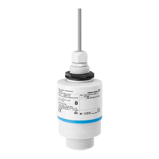
Page 10: Product Description
Product description Micropilot FMR10 Product description Product design 6.1.1 Micropilot FMR10 A0028415 1 Design of the Micropilot FMR10 (26 GHz) Sensor housing Seal Process connection rear side Cable gland Pipe adapter O-ring Counter nut Design ring Process connection front side... -
Page 11: Incoming Acceptance And Product
Order code: Mat.: Ser. no.: DELIVERY NOTE Ext. ord. cd.: A0028673 MWP: T max: DeviceID: Dev.Rev.: ex works if modification see sep. label Date: A0029102 If one of these conditions is not satisfied, contact your Endress+Hauser Sales Center. Endress+Hauser... -
Page 12: Product Identification
(www.endress.com/deviceviewer): All information about the measuring device and an overview of the scope of the associated Technical Documentation is displayed. • Enter the serial number from the nameplates into the Endress+Hauser Operations App, or scan the 2-D matrix code (QR code) on the nameplate with the Endress+Hauser Operations App: All information about the measuring device and an overview of the scope of the associated Technical Documentation is displayed. -
Page 13: Installation
Micropilot FMR10 Installation Installation Installation conditions 8.1.1 Installation types A0028892 3 Wall, ceiling or nozzle installation Wall or ceiling mount, adjustable Mounted at front thread Mounted at rear thread Ceiling installation with counter nut (included in delivery) Caution! The sensor cable is not designed as supporting cable. Do not use as a suspension wire. -
Page 14: Orientation
Installation Micropilot FMR10 8.1.3 Orientation 1/6D A0028410 5 Tank installation position • If possible install the sensor so that its lower edge projects into the vessel. • Do not install the sensor in the middle of the tank (2). We recommend leaving a distance (1) between the sensor and the tank wall measuring 1/6 of the tank diameter. -
Page 15: Beam Angle
If the outer wall of the vessel is made of a non-conductive material (e.g. GFR) microwaves can also be reflected off interfering installations outside of the vessel (e.g. metallic pipes (1), ladders (2), grates (3), ...). Therefore there should be no such interfering installations in the signal beam. For more information, please contact Endress+Hauser. Endress+Hauser... -
Page 16: Weather Protection Cover
Installation Micropilot FMR10 A0029540 8 Measurement in a plastic vessel 8.1.7 Weather protection cover For outdoor use, the use of a weather protection cover(1) is recommended A0031277 9 Weather protection cover, e.g with 40 mm (1.5") antenna The sensor is not completely covered. -
Page 17: Installation With Mounting Bracket, Adjustable
Micropilot FMR10 Installation A0030394 10 Function of flooding protection tube Air pocket O-ring (EPDM) seal Blocking distance Max. Level The flooding protection tube is available as an accessory. → 34 The tube is screwed directly onto the sensor and seals off the system by means of an O- ring (2) making it air-tight. -
Page 18: Cantilever Installation, With Pivot
Installation Micropilot FMR10 NOTICE There is no conductive connection between the mounting bracket and transmitter housing. Risk of electrostatic charge. ‣ Integrate the mounting bracket in the local potential equalization system. The mounting bracket is available as an accessory. → 34 8.1.10... -
Page 19: Electrical Connection
A0029226 Potential equalization No special measures for potential equalization are required. Various power supply units can be ordered from Endress+Hauser. Battery operation The sensor' s Bluetooth® wireless technology communication can be disabled to increase the operating life of the battery. -
Page 20: Connection 4 To 20 Ma
FMR10 connection with voltage source and 4 to 20 mA display A0028907 14 FMR10 block diagram Micropilot FMR10, 4 to 20 mA Power supply Post-connection check Is the device or cable undamaged (visual check)? Do the cables have adequate strain relief? ... -
Page 21: Operability
Micropilot FMR10 Operability Operability 10.1 Operating concept • 4 to 20 mA • SmartBlue (app) via Bluetooth® wireless technology • Menu guidance with brief explanations of the individual parameter functions in the operating tool 10.2 Via Bluetooth® wireless technology A0028895 ... -
Page 22: Commissioning And Operation
Commissioning and operation Micropilot FMR10 Commissioning and operation 11.1 Installation and function check Make sure that all final checks have been completed before you start up your measuring point. 11.2 Operation and settings via SmartBlue (app) SmartBlue is available as download for Android devices from the Google Play Store and for iOS devices from the iTunes Store. - Page 23 Micropilot FMR10 Commissioning and operation 3. Select device from livelist. All available devices are displayed. EH_FMRx0_0123456 A0029502 17 Livelist 4. Perform login EH_FMRx0_0123456 admin A0029503 18 Login 5. Enter user name -> admin 6. Enter initial password -> device serial number 7.
- Page 24 Commissioning and operation Micropilot FMR10 8. You can drag additional information (e.g. main menu) onto the screen by swiping across the screen. EH_FMRx0_0123456 Micropilot FMRx0 EH_FMRx0_0123456 A0000123456 1234 FMRx0-1234/0 EH_FMRx0_0123456 A0029504 19 Main menu Envelope curves can be displayed and recorded Additionally to the envelope curve, the following values are displayed: •...
- Page 25 Micropilot FMR10 Commissioning and operation 0123456 A0000123456 A0029486 20 Android view Record video Create screenshot Start / stop video recording Send video Navigate to mapping menu Move time on time axis Endress+Hauser...
- Page 26 Commissioning and operation Micropilot FMR10 0123456 A0000123456 Envelope Curve Map Curve Weighting Curve A0029487 21 iOS view Record video Create screenshot Send video Navigate to mapping menu Start / stop video recording Move time on time axis Endress+Hauser...
-
Page 27: Configuring Level Measurement Via Operating
Micropilot FMR10 Commissioning and operation 11.3 Configuring level measurement via operating software 100% A0028417 22 Configuration parameters for level measurement in liquids Reference point of measurement Distance Level Empty calibration (= zero point) Full calibration (= span) BD Blocking distance 1. -
Page 28: Displaying Level Value As
Commissioning and operation Micropilot FMR10 11.3.1 Displaying level value as % In combination Full calibration with Empty calibration and given 4 to 20 mA output signal, the level value for 4 mA (=Empty) and the level value for 20 mA (=Full) can be determined directly in the unit of length used. -
Page 29: Data Access - Security
Micropilot FMR10 Commissioning and operation 11.4 Data access - Security 11.4.1 Software locking via access code in SmartBlue The configuration data can be write-protected using an access code (software locking). ‣ Navigate to: Setup → Advanced setup → Administration → Administration1 → Define access code →... -
Page 30: Diagnostics And Troubleshooting
Diagnostics and troubleshooting Micropilot FMR10 Diagnostics and troubleshooting 12.1 General trouble shooting 12.2 General errors Error Possible cause Remedy Device is not responding. Supply voltage does not match the Apply correct voltage value indicated on the nameplate The polarity of the supply voltage is... -
Page 31: Diagnostic Event
Micropilot FMR10 Diagnostics and troubleshooting 12.3 Diagnostic event 12.3.1 Diagnostic event in the operating tool If a diagnostic event is present in the device, the status signal appears in the top left status in the operating tool along with the corresponding symbol for event level in accordance with NAMUR NE 107: •... -
Page 32: Maintenance
Maintenance Micropilot FMR10 Diagnostic Short text Remedy instructions Status signal Diagnostic number [from the behavior factory] [from the factory] Record map Recording of mapping Warning please wait Diagnostic of process Energy too low Increase supply voltage Warning Operating 1. Check ambient temperature... -
Page 33: Repair
14.1 General notes 14.1.1 Repair concept The Endress+Hauser repair concept is devised in such a way that repairs can only be carried out through device replacement. 14.1.2 Replacing a device Once the device has been replaced, parameters must be reconfigured and interference echo suppression or linearization may need to be carried out once again. -
Page 34: Accessories
Accessories Micropilot FMR10 Accessories 15.1 Overview Device-specific accessories Accessories Description Order number Weather protection cover Material: PVDF 52025686 The sensor is not completely covered. Securing nut G1-1/2 Suitable for use with devices with G 1-1/2 and MNPT 1-1/2 52014146 process connection. -
Page 35: Operating Menu
Micropilot FMR10 Operating menu Operating menu 16.1 Overview operating menue (SmartBlue) Navigation Operating menu Main menu ‣ Setup → 39 ‣ Basic setup Device tag → 39 Distance unit → 39 → 39 Empty calibration →... - Page 36 Operating menu Micropilot FMR10 First Echo sensitivity → 43 Output mode → 43 Blocking distance → 44 Level correction → 44 Evaluation distance → 44 ‣ → 46 Safety settings Delay time echo lost →...
- Page 37 Micropilot FMR10 Operating menu ‣ Linearization table Distance unit → 39 Linearization type → 45 Level linearized → 45 ‣ Communication → 52 ‣ Bluetooth configuration → 52 Bluetooth mode → 52 ‣ Diagnostics →...
- Page 38 Operating menu Micropilot FMR10 Value current output 1 → 57 Process variable value → 57 Endress+Hauser...
-
Page 39: Setup" Menu
Micropilot FMR10 Operating menu 16.2 "Setup" menu • : Indicates how to navigate to the parameter using operating tools • : Indicates parameters that can be locked via the access code. Navigation Setup Device tag Navigation Setup → Device tag... -
Page 40: Signal Quality
Operating menu Micropilot FMR10 User entry 0.0 to 5 m Factory setting 4.8 m Distance Navigation Setup → Distance Description Displays the current measured distance D from the reference point (lower edge of the flange / last thread of the sensor) to the level. - Page 41 Micropilot FMR10 Operating menu Confirm distance Navigation Setup → Confirm distance Description Does the measured distance match the real distance? Select one of the options: - Manual map To be selected if the range of mapping is to be defined manually in the ' M apping end point' parameter.
-
Page 42: Advanced Setup" Submenu
Define access code parameter has to be entered. If an incorrect access code is entered, the device remains in the Operator Mode. Please contact your Endress+Hauser Sales Center if you lose your access code. User entry... -
Page 43: First Echo Sensitivity
Micropilot FMR10 Operating menu Changing velocity Navigation Setup → Advanced setup → Changing vel. Description Selection of the expected draining or filling speed of the measured level. Selection • Slow <10 cm (0,4 in)/min • Standard <1 m (40 in)/min •... -
Page 44: Blocking Distance
Operating menu Micropilot FMR10 Blocking distance Navigation Setup → Advanced setup → Blocking dist. Description Specify blocking distance (BD). No signals are evaluated within the blocking distance. Therefore, BD can be used to suppress interference signals in the vicinity of the antenna. -
Page 45: Linearization Type
Micropilot FMR10 Operating menu Linearization type Navigation Setup → Advanced setup → Lineariz. type Description Linearization types Meaning of the options: • None: The level is transmitted in the level unit without linearization. • Table: The relationship between the measured level L and the output value(volume/flow/ weight) is given by a linearization table consisting of up to 32 pairs of values "level -... -
Page 46: Safety Settings
Operating menu Micropilot FMR10 "Safety settings" submenu Navigation Setup → Advanced setup → Safety sett. Delay time echo lost Navigation Setup → Advanced setup → Safety sett. → Delay echo lost Description Define the delay time in the case of an echo loss. After an echo loss, the device waits for the time specified in this parameter before reacting as specified in the Diagnostic echo lost parameter. -
Page 47: Current Output
Micropilot FMR10 Operating menu "Current output" submenu Navigation Setup → Advanced setup → Curr.output Output current Navigation Setup → Advanced setup → Curr.output → Output curr. Description Shows the actual calculated value of the output current. User interface 3.59 to 22.5 mA... -
Page 48: Ma Value
Operating menu Micropilot FMR10 4 mA value Navigation Setup → Advanced setup → Curr.output → 4 mA value Description Value for 4-mA at ' T urn down parameter' = On Using the turn down functionality it is possible to map a section of the measuring range to the total range of the output current (4-20mA). -
Page 49: Trim Value High
Micropilot FMR10 Operating menu Selection • Off • 4 mA • 20 mA • Calculate • Reset Factory setting Trim value high Navigation Setup → Advanced setup → Curr.output → Trim value high Description Enter upper measured value for the trim (around 20 mA). After this value has been entered: Select ' T rim' = Calculate. -
Page 50: Administration
' E nter access code' parameter. The new access code is only valid after it has been confirmed in the ' C onfirm access code' parameter. Please contact your Endress+Hauser Sales Center if you lose your access code. -
Page 51: Free Field Special
Micropilot FMR10 Operating menu Free field special Navigation Setup → Advanced setup → Administration → Free field spec. Description Switch the free field option on or off. This parameter can be switched on for free field applications (e.g. below bridges). Caution: The customer map (if one exists) is reset to the factory map!. -
Page 52: Communication" Submenu
Operating menu Micropilot FMR10 16.2.2 "Communication" submenu Navigation Setup → Communication "Bluetooth configuration" submenu Navigation Setup → Communication → Bluetooth conf. Bluetooth mode Navigation Setup → Communication → Bluetooth conf. → Bluetooth mode Description Enable or disable Bluetooth function.. Remark: Switching to position ' O ff' will disable remote access via the app with immediate effect. -
Page 53: Diagnostics" Submenu
Micropilot FMR10 Operating menu 16.3 "Diagnostics" submenu Navigation Diagnostics Actual diagnostics Navigation Diagnostics → Actual diagnos. Description Displays current diagnostic message. If several messages are active at the same time, the messages with the highest priority is displayed. - Page 54 Operating menu Micropilot FMR10 User interface • Strong • Medium • Weak • No signal Endress+Hauser...
-
Page 55: Device Information" Submenu
Micropilot FMR10 Operating menu 16.3.1 "Device information" submenu Navigation Diagnostics → Device info Device name Navigation Diagnostics → Device info → Device name Description Shows the name of the transmitter. Factory setting Micropilot FMR10 Firmware version Navigation ... -
Page 56: Order Code
Operating menu Micropilot FMR10 Order code Navigation Diagnostics → Device info → Order code Description Shows the device order code. Serial number Navigation Diagnostics → Device info → Serial number Description Shows the serial number of the measuring device. -
Page 57: Simulation" Submenu
Micropilot FMR10 Operating menu 16.3.2 "Simulation" submenu Navigation Diagnostics → Simulation Simulation Navigation Diagnostics → Simulation → Simulation Description Select process variable to be simulated. The Simulation is used to simulate specific measuring values or other conditions. This helps to check the correct configuration of the device and connected control units. -
Page 58: Index
Advanced setup ......42 Evaluation sensitivity (Parameter) ....42 Endress+Hauser... - Page 59 Value current output 1 (Parameter) ....57 Workplace safety ......7 Endress+Hauser...
- Page 60 www.addresses.endress.com...