Endress+Hauser Micropilot FMR50 Brief Operating Instructions
Level radar
Hide thumbs
Also See for Micropilot FMR50:
- Description (160 pages) ,
- Safety instructions (88 pages) ,
- Technical information (80 pages)
Table of Contents
Advertisement
Quick Links
KA01128F/00/EN/01.13
71217610
Products
Brief Operating Instructions
Micropilot FMR50
Level radar
These Instructions are Brief Operating Instructions; they do not
replace the Operating Instructions included in the scope of
supply.
For detailed information, refer to the Operating Instructions
and other documentation on the CD-ROM provided or visit
"www.endress.com/deviceviewer".
Solutions
Services
Advertisement
Table of Contents

Related Manuals for Endress+Hauser Micropilot FMR50


Summary of Contents for Endress+Hauser Micropilot FMR50
- Page 1 Products Solutions Services KA01128F/00/EN/01.13 71217610 Brief Operating Instructions Micropilot FMR50 Level radar These Instructions are Brief Operating Instructions; they do not replace the Operating Instructions included in the scope of supply. For detailed information, refer to the Operating Instructions and other documentation on the CD-ROM provided or visit...
-
Page 2: Table Of Contents
Table of contents Micropilot FMR50 Table of contents Important document information ......... . 3 Document conventions . -
Page 3: Important Document Information
Micropilot FMR50 Important document information Important document information Document conventions 1.1.1 Safety symbols Symbol Meaning DANGER! DANGER This symbol alerts you to a dangerous situation. Failure to avoid this situation will result in serious or fatal injury. A0011189-EN WARNING! WARNING This symbol alerts you to a dangerous situation. - Page 4 Important document information Micropilot FMR50 1.1.3 Tool symbols A0011222 A0011220 A0011219 A0013442 A0011221 Cross-head Flat blade Torx screwdriver Allen key Hexagon wrench screwdriver screwdriver 1.1.4 Symbols for certain types of information Symbol Meaning Allowed Indicates procedures, processes or actions that are allowed.
- Page 5 Micropilot FMR50 Important document information Symbol Meaning Hazardous area Indicates a hazardous area. A0011187 Safe area (non-hazardous area) Indicates a non-hazardous location. A0011188 1.1.6 Symbols at the device Symbol Meaning Safety instructions Observe the safety instructions contained in the associated Operating Instructions.
-
Page 6: Basic Safety Instructions
The manufacturer is not liable for damage caused by improper or non-designated use. Verification for borderline cases: ‣ For special measured materials and cleaning agents, Endress+Hauser is glad to provide assistance in verifying the corrosion resistance of wetted materials, but does not accept any warranty or liability. -
Page 7: Workplace Safety
It meets general safety standards and legal requirements. It also complies with the EC directives listed in the device-specific EC Declaration of Conformity. Endress+Hauser confirms this by affixing the CE mark to the device. -
Page 8: Product Description
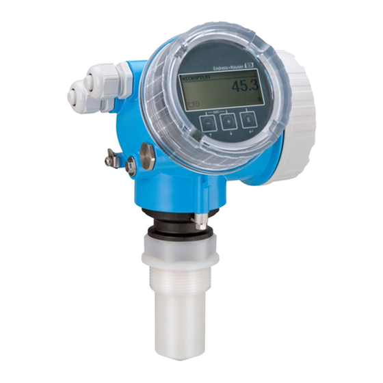
Product description Product design 3.1.1 Micropilot FMR50 A0016784 1 Design of the Micropilot FMR50 (26 GHz) Electronics housing Process connection (Thread) Horn antenna 40 mm (1-1/2 in), PVDF encapsulated Horn antenna 80mm/100 mm (3in/4 in), PP cladded Slip-on flange... - Page 9 Micropilot FMR50 Product description 3.1.2 Electronics housing A0012422 2 Design of the electronics housing Electronics compartment cover Display module Main electronics module Cable glands (1 or 2, depending on instrument version) Nameplate I/O electronics module Terminals (pluggable spring terminals)
-
Page 10: Incoming Acceptance And Product Identification
Incoming acceptance and product identification Micropilot FMR50 Incoming acceptance and product identification Incoming acceptance DELIVERY NOTE 1 = 2 A0013696 A0016870 A0016871 A0013696 A0016872 Endress+Hauser... - Page 11 Micropilot FMR50 Incoming acceptance and product identification Made in Germany, 79689 Maulburg DELIVERY NOTE A0013696 A0014038 A0013696 A0014037 If one of the conditions does not comply, contact your Endress+Hauser distributor. Endress+Hauser...
-
Page 12: Product Identification
Incoming acceptance and product identification Micropilot FMR50 Product identification The following options are available for identification of the measuring device: • Nameplate specifications • Extended order code with breakdown of the device features on the delivery note • Enter serial numbers from nameplates in W@M Device Viewer www.endress.com/deviceviewer... -
Page 13: Storage, Transport
Micropilot FMR50 Storage, Transport Storage, Transport Storage conditions • Permitted storage temperature: –40 to +80 °C (–40 to +176 °F) • Use the original packaging. Transport product to the measuring point NOTICE Housing or antenna horn may be damaged or break away. -
Page 14: Installation
Installation Micropilot FMR50 Installation Installation conditions 6.1.1 Mounting position • Recommended distance A from wall to outer edge of nozzle: ~ 1/6 of tank diameter. Nevertheless the device should not be installed closer than 15 cm (5.91 in) to the tank wall. - Page 15 Micropilot FMR50 Installation 6.1.2 Vessel installations Avoid any installations (limit switches, temperature sensors, braces, vacuum rings, heating coils, baffles etc.) inside the signal beam. Take into account the beam angle (→ 19). A0018944 Endress+Hauser...
- Page 16 (e.g. metallic pipes (1), ladders (2), grates (3), ...). Therefore, there should be no such interfering installations in the signal beam. Please contact Endress+Hauser for further information. Endress+Hauser...
- Page 17 Micropilot FMR50 Installation A0017123 Endress+Hauser...
- Page 18 Installation Micropilot FMR50 6.1.5 Optimization options • Antenna size The bigger the antenna, the smaller the beam angle α and the fewer interference echoes (→ 19). • Mapping The measurement can be optimized by means of electronic suppression of interference echoes.
- Page 19 Micropilot FMR50 Installation 6.1.6 Beam angle A0016891 4 Relationship between beam angle α, distance D and beamwidth diameter W The beam angle is defined as the angle α where the energy density of the radar waves reaches half the value of the maximum energy density (3-dB-width). Microwaves are also emitted outside the signal beam and can be reflected off interfering installations.
-
Page 20: Measuring Conditions
• The tank height should be at least H (see table). Affected compounds are e.g. R134a, R227, Dymel 152a. Dielectric constants of important media commonly used in the industry are summarized in the document SD106F, which can be downloaded from the Endress+Hauser web page (www.endress.com). Endress+Hauser... - Page 21 Micropilot FMR50 Installation 100% øD A0018872 Device A [mm (in)] B [m (ft)] C [mm (in)] H [m (ft)] FMR50 150 ( > 0.2 (0.7) 50 to 250 (1.97 to 9.84) > 0.3 (1.0) 5.91) Endress+Hauser...
-
Page 22: Installation In Vessel (Free Space)
Installation Micropilot FMR50 Installation in vessel (free space) 6.3.1 Horn antenna encapsulated (FMR50) Alignment • Align the antenna vertically to the product surface. • A marking at the threaded connection enables alignment of the antenna. This marking must be aligned towards the tank wall as well as possible. - Page 23 Antenna size 40 mm (1½ in) 39 mm (1.54 in) < 60 mm (2.36 in) Please contact Endress+Hauser for applications with higher nozzle. Threaded connection • Tighten with the hexagonal nut only. • Tool : Hexagonal wrench 50 mm • Maximum permissible torque: 35 Nm (26 lbf ft)
- Page 24 Installation Micropilot FMR50 6.3.2 Horn antenna with slip-on flange (FMR50) Alignment When using the Micropilot with a slip-on flange in explosion-hazardous areas, strictly observe all specifications in the relevant Safety Instructions (XA). • Align the antenna vertically to the product surface.
- Page 25 Micropilot FMR50 Installation Nozzle mounting øD A0016868 6 Nozzle height and diameter for horn antenna with slip-on flange (FMR50/FMR56) Antenna 80 mm (3 in) 100 mm (4 in) size 80 mm (3.15 in) 100 mm (3.94 in) 150 mm (5.91 in) 100 mm (3.94 in) 150 mm (5.91 in) <...
- Page 26 Installation Micropilot FMR50 6.3.3 Horn antenna with mounting bracket (FMR50) A0016865 7 Installation of the horn antenna with mounting bracket (FMR50/FMR56) Align the antenna vertically to the product surface using the mounting bracket. NOTICE The mounting bracket has no conductive connection to the transmitter housing.
-
Page 27: Installation In Stilling Well
Micropilot FMR50 Installation Installation in stilling well A0016841 8 Installation in stilling well Marking for antenna alignment • For horn antenna: Align the marking towards the slots of the stilling well. • Measurements can be performed through an open full bore ball valve without any problems. -
Page 28: Installation In Bypass
Installation Micropilot FMR50 Installation in bypass A0019446 9 Installation in bypass Marking for antenna alignment Tank connectors • Alighn the marker perpendicular (90°) to the tank connectors. • Measurements can be performed through an open full bore ball valve without any problems. -
Page 29: Vessels With Heat Insulation
Micropilot FMR50 Installation Vessels with heat insulation A0019141 If process temperatures are high, the device must be included in normal tank insulation to prevent the electronics heating up as a result of heat radiation or convection. The insulation may not exceed beyond the neck of the housing. -
Page 30: Turning The Display Module
Installation Micropilot FMR50 Tighten the securing screw (1,5 Nm for plastics housing; 2,5 Nm for aluminium or stainless steel housing). Turning the display module 3 mm A0013905 Loosen the screw of the securing clamp of the electronics compartment cover using an Allen key and turn the clamp 90° conterclockwise. - Page 31 Micropilot FMR50 Installation Is the device adequately protected from precipitation and direct sunlight? Are the securing screw and securing clamp tightened securely? Endress+Hauser...
-
Page 32: Electrical Connection
Electrical connection Micropilot FMR50 Electrical connection Connection conditions 7.1.1 Cable specification For ambient temperature T ≥60 °C (140 °F): use cable for temperature T +20 K. PROFIBUS Use a twisted, screened two-wire cable, preferably cable type A. For further information on the cable specifications, see Operating Instructions BA00034S "Guidelines for planning and commissioning PROFIBUS DP/PA", PNO... - Page 33 Micropilot FMR50 Electrical connection 7.1.2 Terminal assignment PROFIBUS PA / FOUNDATION Fieldbus A0011341 10 Terminal assignment PROFIBUS PA / FOUNDATION Fieldbus Without integrated overvoltage protection With integrated overvoltage protection Cable screen: Observe cable specifications (→ 32) Terminals for switch output (open collector)
- Page 34 Electrical connection Micropilot FMR50 Connection examples for the switch output A0015909 A0015910 11 Connection of a relay 12 Connection of a digital input Pull-up resistor Suitable relays (examples): Digital input • Solid-state relay: Phoenix Contact OV-24DC/480AC/5 with mounting rail connector UMK-1 OM-R/AMS •...
- Page 35 Micropilot FMR50 Electrical connection 7.1.3 Device plug connectors For the versions with fieldbus plug connector (M12 or 7/8"), the signal line can be connected without opening the housing. Pin assignment of the M12 plug connector Meaning Signal + not connected...
- Page 36 Electrical connection Micropilot FMR50 7.1.4 Supply voltage PROFIBUS PA, FOUNDATION Fieldbus "Power supply; Output" "Approval" Terminal voltage E: 2-wire; FOUNDATION Fieldbus, switch output (in • Non-Ex 9 to 32 V preparation) • Ex nA G: 2-wire; PROFIBUS PA, switch output •...
- Page 37 < 1.5 pF Nominal arrest impulse voltage (⁸⁄₂₀ μs) 10 kA External overvoltage protection HAW562 or HAW569 from Endress+Hauser are suited as external overvoltage protection. For detailed information please refer to the following documents: • HAW562: TI01012K • HAW569: TI01013K...
-
Page 38: Connecting The Measuring Device
Electrical connection Micropilot FMR50 Connecting the measuring device WARNING Explosion hazard! ‣ Comply with the relevant national standards. ‣ Observe the specifications in the Safety Instructions (XA). ‣ Only use the specified cable glands. ‣ Check whether the supply voltage matches the specifications on the nameplate. - Page 39 Micropilot FMR50 Electrical connection A0013837 Connect the cable in accordance with the terminal assignment (→ 33). When using screened cable: Connect the cable screen to the ground terminal. Screw the cover onto the connection compartment. 10. For instruments with safety pin for the lid: Adjust the safety pin so that its edge is over the edge of the display lid.
- Page 40 Electrical connection Micropilot FMR50 ≤ 3 (0.12) mm (in) A0013661 Endress+Hauser...
-
Page 41: Post-Connection Check
Micropilot FMR50 Integration into a PROFIBUS network Post-connection check Are cables or the device undamaged (visual inspection)? Do the cables comply with the requirements? Do the cables have adequate strain relief? Are all cable glands installed, firmly tightened and correctly sealed? Does the supply voltage match the specifications on the transmitter nameplate? Is the terminal assignment correct (→... - Page 42 Integration into a PROFIBUS network Micropilot FMR50 8.2.1 Hardware adressing Set switch 8 to "OFF". Define the address with switches 1 to 7 according to the table below. The address change becomes effective after 10 seconds. The device restarts automatically.
-
Page 43: Commissioning
Micropilot FMR50 Commissioning Commissioning Display and operating module 9.1.1 Display appearance User ABC_ DEFG HIJK LMNO PQRS TUVW A0012635 16 Appearance of the display and operation module for on-site operation Measured value display (1 value max. size) 1.1 Header containing tag and error symbol (if an error is active) 1.2 Measured value symbols... - Page 44 Commissioning Micropilot FMR50 9.1.2 Operating elements Meaning Minus key For menu, submenu Moves the selection bar upwards in a picklist. A0013969 For text and numeric editor In the input mask, moves the selection bar to the left (backwards). Plus key For menu, submenu Moves the selection bar downwards in a picklist.
-
Page 45: Operating Menu
Micropilot FMR50 Commissioning Operating menu Parameter/Submenu Meaning Description Language Defines the operating language of the on-site display. Setup When appropriate values have been assigned toall setup parameters, the measured should be completely configured in a standard application. Setup → Mapping Interference echo suppression Setup →... -
Page 46: Unlock The Device
Commissioning Micropilot FMR50 Unlock the device If the device has been locked, it must be unlocked before the measurement can be configured. For details refer to the Operating Instructions of the device: BA01124F (FMR50, PROFIBUS PA) Setting the operating language... -
Page 47: Configuration Of A Level Measurement
Micropilot FMR50 Commissioning Configuration of a level measurement 100% A0016933 Setup → Tag description Enter tag for measuring point. Setup → Device address Enter bus address of the device (only in case of software addressing). Setup → Distance unit ... - Page 48 Commissioning Micropilot FMR50 Setup → Full calibration Enter full distance F (Distance from the 0% to the 100% level). Setup → Level Indicates the measrued level L. 10. Setup → Distance Indicates the measured distance from the reference point R to the level L.
-
Page 49: User-Specific Applications
Micropilot FMR50 Commissioning User-specific applications For details of setting the parameters of user-specific applications, see separate documentation: BA01124F (Operating Instructions, FMR50, PROFIBUS PA) For the Expert submenu refer to: GP01018F/00/EN (Description of Device Parameters, FMR5x, PROFIBUS PA) Endress+Hauser... - Page 52 *71217610* 71217610 www.addresses.endress.com...