
Related Manuals for Endress+Hauser HART Proline Prosonic Flow 91


Summary of Contents for Endress+Hauser HART Proline Prosonic Flow 91
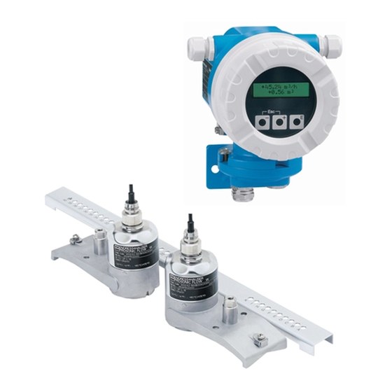
- Page 1 Operating Instructions Proline Prosonic Flow 91 HART Ultrasonic Flow Measuring System BA00100D/06/EN/13.11 71130013 Valid as of software version V 1.02.XX (electronics board)
- Page 2 All functions are described in detail, as is the function matrix itself ä 75. Note! Always start troubleshooting with the checklist on ä 55 if faults occur after commissioning or during operation. This takes you directly (via various queries) to the cause of the problem and the appropriate remedial measures. Endress+Hauser...
-
Page 3: Table Of Contents
3.10.1 Connecting Prosonic Flow W ..27 8.2.1 Category F diagnosis code messages ..56 8.2.2 Category C diagnosis code messages ..57 Endress+Hauser... - Page 4 10.22.1 SI units ......113 10.22.2 US units (for USA and Canada only) ..113 Endress+Hauser...
-
Page 5: Safety Instructions
• The device must be operated by persons authorized and trained by the plant operator. Strict compliance with the instructions in these Operating Instructions is mandatory. • Endress+Hauser is willing to assist in clarifying the chemical resistance properties of parts wetted by special fluids, including fluids used for cleaning. However, small changes in temperature, concentration or the degree of contamination in the process can result in changes to the chemical resistance properties. -
Page 6: Return
Endress+Hauser: • Always enclose a duly completed "Declaration of Contamination" form. Only then can Endress+Hauser transport, examine and repair a returned device. Note! You will find a preprinted "Declaration of Contamination" form at the back of this manual. -
Page 7: Identification
Power supply, frequency, power consumption Outputs available: I-OUT (HART): with current output (HART) PULSE-OUT: with pulse/status output Reserved for additional information on device version (approvals, certificates) Permitted ambient temperature range Degree of protection Please comply with the Operating Instructions Endress+Hauser... -
Page 8: Nameplate Of The Sensor
Please comply with the Operating Instructions Reserved for additional information on device version (approvals, certificates) Degree of protection Permitted ambient temperature range 2.1.3 Nameplate of the connections – – L1 (L+) N (L–) a0005394 Fig. 3: Nameplate specifications for the transmitter (example) Endress+Hauser... -
Page 9: Certificates And Approvals
EMC requirements of IEC/EN 61326. The measuring system described in these Operating Instructions therefore complies with the legal requirements of the EU Directives. Endress+Hauser confirms this by affixing the CE mark to it and by issuing the CE Declaration of Conformity. -
Page 10: Installation
• The storage temperature corresponds to the ambient temperature range of the transmitter, the measuring sensors and the corresponding sensor cables ä 72. • The measuring device must be protected against direct sunlight during storage in order to avoid unacceptably high surface temperatures. Endress+Hauser... -
Page 11: Installation Conditions
Correct measuring is possible only if the pipe is full. Avoid the following mounting locations: • Do not install at the highest point in the run. Risk of air accumulating! • Do not install directly upstream from an open pipe outlet in a down pipe. a0001103 Fig. 4: Mounting location Endress+Hauser... -
Page 12: Orientation
³ 15 x DN ³ 3 x DN ³ 20 x DN ³ 20 x DN ³ 15 x DN A0013079 Fig. 6: Inlet and outlet runs (top view) Valve (2/3 open) Pump Double bends Endress+Hauser... -
Page 13: Sensor Selection And Arrangement
>10 mm, or applications with media with high acoustic damping. In addition, for these applications we principally recommend mounting the W sensors in a 1 traverse configuration. 6 MHz sensors for applications where flow velocity 10m/s (32.8Hz/s) Endress+Hauser... -
Page 14: Preparatory Steps Prior To Installation
– Local operation of the device – FieldCare (operating program), connect a notebook to the transmitter – Applicator (software), online on the Endress+Hauser Internet site Mechanical preparation of the clamp-on retainers for the sensors: – Premount the strapping bands (DN 50 to 200 / 2 to 8") or (DN 250 to 4000 / 10 to 160") –... -
Page 15: Mechanical Preparation
Note! The visible pipe surface "A" must be smooth to ensure good acustic contact. A0011524 Fig. 8: Mounting the Prosonic Flow-sensor holder (DN 15 to 65 / ½ to 2½") with U-shaped screws Endress+Hauser... -
Page 16: Mounting The Sensor Holder With Strapping
Risk of injury. To avoid sharp edges, trim the cut edges after shortening the strapping bands. A0011525 Fig. 9: Positioning the sensor holder and mounting the strapping bands Note! The visible pipe surface "A" must be smooth to ensure good acustic contact. A0011526 Fig. 10: Tightening the strapping screws of the strapping bands Endress+Hauser... -
Page 17: Premounting The Strapping Bands (Medium Nominal Diameters)
Where necessary, shorten the strapping bands and trim the cut edges. Warning! Risk of injury. To avoid sharp edges, trim the cut edges after shortening the strapping bands. A0001109 Premounting strapping bands for pipe diameters DN 200 (8") Fig. 11: Mounting bolt Strapping band Strapping screw Endress+Hauser... -
Page 18: Premounting The Strapping Bands (Large Nominal Diameters)
( 2 0 ³ 5 A0015461 Fig. 12: Premounting strapping bands for pipe diameters DN > 600 (24 ") Mounting bolt with guide* Strapping band* Strapping screw Distance between mounting bolt and strapping band lock min 500 mm (20 in) Endress+Hauser... -
Page 19: Installing Prosonic Flow W Sensor
Fit the sensor housing on the sensor holder. Note! • Avoid to use a thick layer of the coupling fluid (less is more). • Clean and reapply new coupling fluid when sensor is removed from the pipe. A0011527 Fig. 14: Fitting the sensor housing Endress+Hauser... - Page 20 – The bracket can only be released using an auxiliary tool. A0011528 Fig. 15: Fixing the sensor housing Connect the connecting cable to the adapter cable. This completes the mounting process. The sensors can now be connected to the transmitter via the connecting cables ä 27. Endress+Hauser...
-
Page 21: Installing Prosonic Flow W (Dn 50 To 4000 / 2" To 160")
Take the still movable strapping band, incl. the mounting bolt, and move it until both measuring wires are evenly tensioned and tighten the strapping band so that it cannot slip. A0001113 Fig. 17: Positioning the strapping bands (steps 2 to 4) Endress+Hauser... - Page 22 Fit the sensor cover on the sensor holder and turn until: – The sensor cover engages with a click – The arrows (Å / Æ "close") are pointing towards one another. 10. Screw the connecting cable into the individual sensor. Endress+Hauser...
- Page 23 – Position the movable strapping band and slide the mounting rail with the bore identified by the numerical value from POSITION SENSOR over the mounting bolt. Endress+Hauser...
- Page 24 Fit the sensor cover on the sensor holder and turn until: – The sensor cover engages with a click – The arrows (Å / Æ "close") are pointing towards one another. Screw the connecting cable into the individual sensor. Endress+Hauser...
- Page 25 Turn the display to the desired position (max. 4 × 45° in each direction). Place the display back on the retaining rails. Screw the cover of the electronics compartment firmly back onto the transmitter housing. 4 x 45° A0003237 Fig. 25: Rotating the local display Endress+Hauser...
-
Page 26: Mounting The Transmitter
Installation Notes Are the measuring point number and labeling correct (visual inspection)? Process environment / process conditions Notes ä 12 Are the inlet and outlet runs respected? Is the measuring device protected against moisture and direct sunlight? Endress+Hauser... -
Page 27: Wiring
In the connection compartment, fix the two sensor connecting cables in place in the holder (i) provided. a0005843 Fig. 27: Connecting the measuring system a, b Sensor connecting cables Cable gland cover Rubber seal Cable fixing sleeves Ground disk Cable gland holder Seal Cable holder Endress+Hauser... -
Page 28: Connecting And Grounding Prosonic Flow W
Remove the cable gland cover again. Then retry to retract with the pair of pliers. Endress+Hauser... -
Page 29: Cable Specifications
3.10.3 Cable specifications Sensor cable • Use the ready-to-use cables supplied by Endress+Hauser with each sensor pair. • The following cable lengths are available: – 5 m, 10 m, 15 m , 30 m, 60 m – 16 ft, 33 ft, 49 ft, 98 ft, 197 ft •... -
Page 30: Connecting The Measuring Unit
Ground terminal for power supply cable Terminal connector for power supply: No. 1–2 ä 31 (terminal assignment) Signal cable Ground terminal for signal cable Terminal connector for signal cable: No. 24–27 ä 31 (terminal assignment) Service connector Ground terminal for potential equalization Endress+Hauser... -
Page 31: Terminal Assignment
(e.g. Commubox FXA 195) is needed. ³ –27 RS 232 a0005574 Fig. 32: Electrical connection of a PC with an operating software PC with an operating software Other evaluation devices or PLC with passive input Shield HART modem, e.g. Commubox FXA 195 Endress+Hauser... -
Page 32: Potential Equalization
IP 67/68 protection is maintained: • Only use cables supplied by Endress+Hauser with the corresponding sensor connectors. • The cable connector seals (1) must be clean, dry and undamaged when inserted in the seal groove. -
Page 33: Post-Connection Check
Are all screw terminals firmly tightened? ä 32 Have the measures for grounding/potential equalization been correctly implemented? ä 32 Are all cable entries installed, firmly tightened and correctly sealed? Are all housing covers installed and firmly tightened? Endress+Hauser... -
Page 34: Operation
– Press and hold down the +/- keys for more than 3 seconds Return directly to HOME position – Cancel data entry Enter key – HOME position Enter the function matrix – Save the numerical values entered or settings changed Endress+Hauser... -
Page 35: Brief Guide To The Function Matrix
– Press and hold down the Esc key (X) for more than 3 seconds HOME position – Repeatedly press Esc key (X) Return step by step to HOME position > 3 s – – – – A0001142 Fig. 36: Selecting functions and configuring parameters (function matrix) Endress+Hauser... -
Page 36: General Notes
• If programming is disabled and the P operating elements are pressed in any function, a prompt for the code automatically appears on the display. • If "0" is specified as the private code, programming is always enabled. • The Endress+Hauser service organization can be of assistance if the personal code is lost. " Caution! Changing certain sensor specific parameters may influence characteristics of numerous functions of the entire measuring device, particularly measuring accuracy. -
Page 37: Communication
Communicator contains more detailed information on the device. Operating program "FieldCare" FieldCare is Endress+Hauser’s FDT-based plant asset management tool and allows the configuration and diagnosis of intelligent field devices. By using status information, you also have a simple but effective tool for monitoring devices. The Proline flowmeters are accessed via a service interface or via the service interface FXA291. -
Page 38: Device Description Files For Operating Programs
The Fieldcheck tester/simulator is used for testing flowmeters in the field. When used in conjunction with the "FieldCare" software package, test results can be imported into a database, printed and used for official certification. Contact your Endress+Hauser representative for more information. -
Page 39: Hart Commands
• Primary process variable = Volume flow • Secondary process variable = Totalizer • Third process variable = Sound velocity • Fourth process variable = Flow velocity Note! • Manufacturer-specific units are represented using the HART unit code "240". Endress+Hauser... - Page 40 – Bytes 4-7: upper sensor limit – Bytes 8-11: lower sensor limit – Bytes 12-15: minimum span Note! • The data relate to the primary process variable (= volume flow). • Manufacturer-specific units are represented using the HART unit code "240". Endress+Hauser...
- Page 41 Access = Write – Bytes 0-5: TAG – Byte 6-17: TAG description – Byte 6-17: TAG description – Bytes 18-20: date – Bytes 18-20: date Write the device production Bytes 0-2: production number Bytes 0-2: production number number Access = Write Endress+Hauser...
- Page 42 • A change of the unit of the primary process variable has a direct impact on the system units. Read extended device status none The current device status is displayed in extended Access = Read form as the response: Encoding: see Table ä 44. Endress+Hauser...
- Page 43 As a response, the current number of the preambles is message responses are inserted in the message responses: displayed in the response message: Access = Write Byte 0: number of preambles (2 to 20) Byte 0: number of preambles Endress+Hauser...
-
Page 44: Device Status/Diagnosis Messages
C - 482 Simulation output - Status S - 461 Signal output -Current S - 461 Signal output - Frequency S - 461 Signal output - Pulse S - 437 Configuration - Sound velocity S - 437 Configuration - Interference Endress+Hauser... -
Page 45: Commissioning
Beginning of standard measuring mode OPERATION Normal measuring mode commences as soon as startup completes. Various measured value and/or status variables appear on the display (HOME position). Note! If startup fails, an error message indicating the cause is displayed. Endress+Hauser... -
Page 46: Commissioning Via A Configuration Program
Pipe sound velocity SOUND VELOCITY PIPE Pipe circumference CIRCUMFERENCE Pipe diameter PIPE DIAMETER Wall thickness WALL THICKNESS Liner material LINER MATERIAL Liner sound velocity SOUND VELOCITY LINER Liner thickness LINER THICKNESS Sensor type SENSOR TYPE Sensor configuration SENSOR CONFIGURATION Endress+Hauser... -
Page 47: Commissioning
A detailed description of all the functions can be found on ä 75 5.3.2 Commissioning Additionally to the settings for the sensor installation ( ä 46) the following functions have to be configured for the standard application: • System units • Outputs Endress+Hauser... -
Page 48: Data Backup/Transmission
• This option can only be executed if the software version of the T-DAT is the same or newer than that of the EEPROM. Otherwise, the error message "TRANSM. SW-DAT" appears after restarting and the LOAD function is then no longer available. SAVE: Data are transferred from the EEPROM to the T-DAT Endress+Hauser... -
Page 49: Application Specific Commissioning
In instances of this nature, please contact your Endress+Hauser service center. • You can view the currently valid zero point value using the "ZERO POINT" function ( ä 104). -
Page 50: Data Storage Devices
– Repeatedly press and release the Esc key (X). Data storage devices At Endress+Hauser, the term HistoROM refers to various types of data storage modules on which process and measuring device data are stored. By plugging and unplugging such modules, device configurations can be duplicated onto other measuring devices to cite just one example. -
Page 51: Maintenance
• On rough pipe surfaces e.g. GRP pipes ensure that the gaps are filled. Apply suffizienet copling fluid. • A change in the signal strength might indicate a dotorration of the coupling fluid. No action is required as long as the signal strength is higher than 50 dB. Endress+Hauser... -
Page 52: Accessories
Accessories Proline Prosonic Flow 91 Accessories Various accessories, which can be ordered separately from Endress+Hauser, are available for the transmitter and the sensor. Your Endress+Hauser service organization can provide detailed information on the order code in question. Device-specific accessories Accessory... -
Page 53: Communication-Specific Accessories
Handheld terminal for remote configuration and for obtaining SFX100 – ******* Field Xpert SFX 100 measured values via the 4 to 20 mA HART current output. Contact your Endress+Hauser representative for more information. Fieldgate FXA320 Gateway for remote interrogation of HART sensors and actuators FXA320 – ***** via Web browser: •... -
Page 54: Service-Specific Accessories
Software for selecting and configuring flowmeters. DXA80 – * Applicator can be downloaded from the Internet or ordered on CD-ROM for installation on a local PC. Contact your Endress+Hauser representative for more information. Fieldcheck Tester/simulator for testing flowmeters in the field. -
Page 55: Troubleshooting
No. 200 – 399: Messages affecting the transmitter. No. 400 – 599: Configuration-related messages (simulation, download, data storage etc.) No. 800 – 999: Process-specific messages Other errors (without error messages) Diagnosis and remedial measures ä 59 Some other error has occurred. Endress+Hauser... -
Page 56: Diagnosis Code Messages
– It is possible that the fluid indicates too much attenuation. (–) – It is possible that the pipe indicates too much attenuation. – Check the sensor spacing (Installation dimensions). – Reduce the number of traverses if possible. Endress+Hauser... -
Page 57: Category C Diagnosis Code Messages
Simulation frequency output active Simulation pulse output active Simulation status output active C 484 Simulation of response to error (outputs) Switch off simulation Alarm Simulation error active (–) C 485 Simulation of volume flow active Switch off simulation Notice Simulation value (–) Endress+Hauser... -
Page 58: Category S Diagnosis Code Messages
"reciprocal value" that a pulse must be present at the connected counter to ensure its registration. Example: The maximum input frequency of the connected totalizer is 10 Hz. The pulse width to be entered is: --------------------- - 50 ms 2 10 Hz 3. Reduce flow Endress+Hauser... -
Page 59: Process Errors Without Messages
The following options are available for tackling problems of this nature: other fault not described above has Request the services of an Endress+Hauser service technician occurred. If you contact our service organization to have a service technician sent out, please be ready with the following... -
Page 60: Response Of Outputs To Errors
The totalizer is paused until the fault is rectified. ACTUAL VALUE The fault is ignored. The totalizer continues to count in accordance with the current flow value. In the event of fault or power supply failure: status output Non-conductive Status output No effect on status output Endress+Hauser... -
Page 61: Spare Parts
Note! You can order spare parts directly from your Endress+Hauser service organization by quoting the serial number printed on the transmitter nameplate ä 7. Choose the Endress+Hauser Device Viewer via web browser: www.endress.com/deviceviewer... -
Page 62: Removing And Installing Electronics Boards
" Caution! Use only genuine Endress+Hauser parts. Commissioning a new electronics board: Switch off power supply. Unscrew cover of the electronics compartment from the transmitter housing. - Page 63 Local display Latches Connectors for sensor cable Connector for power supply Connector for current output and pulse/status output Connector of local display Securing screws of the board carrier Connector of the ground cable Latches for the electronics board T-DAT (transmitter-DAT) Endress+Hauser...
-
Page 64: Replacing The Device Fuse
– Power supply 85 to 250 V AC 1 A slow-blow / 250 V TR5 Installation is the reverse of the removal procedure. " Caution! Use only genuine Endress+Hauser parts. a0005832 Fig. 42: Replacing the device fuse on the electronics board... -
Page 65: Return
Costs incurred for waste disposal and injury (burns, etc.) due to inadequate cleaning will be charged to the owner-operator. The following steps must be taken before returning a flow measuring device to Endress+Hauser, e.g. for repair or calibration: • Always enclose a duly completed "Declaration of contamination" form. Only then can Endress+Hauser transport, examine and repair a returned device. -
Page 66: Technical Data
DN 15 to 4000 (½" to 160") 9.1.3 Input Measured variable Flow velocity (transit time difference proportional to flow velocity) Measuring range Typically v = 0 to 15 (0 to 50 ft/s) with the specified measuring accuracy Operable flow range Over 150 : 1 Endress+Hauser... -
Page 67: Output
See ä 27 Electrical connections Supply voltage Transmitter (power supply) 85 to 250 V AC, 45 to 65 Hz 20 to 28 V AC, 45 to 65 Hz 11 to 40 V DC Sensor Powered by the transmitter Endress+Hauser... - Page 68 Fig. 43: Cable gland for one multicore connecting cable (1 ×Ø 8 mm / 0.31 in) per cable entry A0008152 Fig. 44: Cable gland for two connecting cables (2 × Ø 4 mm / 0.16 in) per cable entry Endress+Hauser...
- Page 69 • Cable entry M20 × 1,5 (8 to 12 mm; 0,31 to 0,47 in) • Thread for cable entries ½" NPT, G ½" Cable specifications Only use the connecting cables supplied by Endress+Hauser. Different versions of the connecting cables are available ä 29. Prosonic Flow •...
-
Page 70: Performance Characteristics
DN 25 to 200 ±0.5 % o.r. ± 7,5 mm/s ±1.5 % o.r. ±2 % o.r. ± 7.5 mm/s > DN 200 ±0.5 % o.r. ± 3 mm/s ±1.5 % o.r. ±2 % o.r. ± 3 mm/s o.r. = of reading Endress+Hauser... -
Page 71: Operating Conditions: Installation
5 m, 10 m, 15 m, 30 m 60 m only available for sensors DN50...4000 15 feet, 30 feet, 45 feet, 90 feet 180 feet only available for sensors DN 2" to 160" Route the cable well clear of electrical machines and switching elements. Endress+Hauser... -
Page 72: Operating Conditions: Environment
–20 to +80 °C (–4 to +176 °F) Optional: 0 to +130 °C (+32 to +266 °F) Medium pressure range Perfect measurement requires that the static fluid pressure is higher than vapor pressure, to avoid (nominal pressure) outgasing. Pressure loss There is no pressure loss. Endress+Hauser... -
Page 73: Mechanical Construction
• Custom configurations for presenting different measured value and status variables • 1 totalizer Local operation via three operating keys (S, O, F) Operating elements Remote operation Operation via HART protocol and FieldCare Languages English, German, Spanish, Italian, French Endress+Hauser... -
Page 74: Certificates And Approvals
Certificates and approvals Ex approval Information about currently available Ex versions (FM, CSA) can be supplied by your Endress+Hauser Sales Center on request. All explosion protection data are given in a separate documentation which is available upon request. CE mark The measuring system is in conformity with the statutory requirements of the EC Directives. -
Page 75: Description Of Device Functions
Proline Prosonic Flow 91 Description of device functions Description of device functions 10.1 Illustration of the function matrix Endress+Hauser... - Page 76 Description of device functions Proline Prosonic Flow 91 Endress+Hauser...
-
Page 77: Group Measuring Values
5-digit floating-point number, including unit and sign (e.g. 8.0000 m/s, 26.247 ft/s) SIGNAL STRENGTH The signal strength appears on the display. Display: 4-digit fixed-point number (e.g. 80.0 dB) Note! To ensure reliable measurement takes place, Prosonic Flow requires a signal strength of > 30 dB. Endress+Hauser... -
Page 78: Group Sensor Setup
The correct information for the sensor cable length and the wall and liner thickness primarily affect the quality of the measurement. Endress+Hauser... -
Page 79: Group System Units
; oz f; gal; Kgal; Mgal; bbl (normal fluids); bbl (beer); bbl (petrochemicals); bbl (filling tanks) Imperial gal; Mgal; bbl (beer); bbl (petrochemicals) Factory setting: Depends on nominal diameter and country (dm to m or US-gal), corresponds to the totalizer unit factory setting ä 113 Endress+Hauser... - Page 80 Use this function to select the unit for the measure of length. The unit you select here is also valid for: • Nominal diameter • Diameter • Wall thickness • Liner thickness • Wire length • Sensor distance Options: MILLIMETER INCH Factory setting: MILLIMETER Endress+Hauser...
-
Page 81: Group Operation
HOME position. • You can also disable programming in this function by entering any number (other than the defined private code). • The Endress+Hauser service organization can be of assistance if you mislay your personal code. DEF.PRIVATE CODE Use this function to enter a personal code to enable programming. - Page 82 Then only the SAVE function is available. • LOAD This function is only possible if the target device has the same software version as, or a more recent software version than, the source device. • SAVE This function is always available. Endress+Hauser...
-
Page 83: Group User Interface
4. The main line and additional line show a "0" in each field for at least 0.75 seconds. 5. The main line and additional line show nothing (blank display) for at least 0.75 seconds. When the test completes the local display returns to its initial state and the setting changes to "OFF". Endress+Hauser... -
Page 84: Group Totalizer
Effective total quantity = 20,196,845 dm Display: Integer with exponent, including sign and unit, e.g. 2 E7 dm RESET TOTALIZER Use this function to reset the sum and the overflow of the totalizer to "zero" (= RESET). Options: Factory setting: Endress+Hauser... -
Page 85: Group Current Output
• If the measured value is outside the measuring range (defined in the VALUE 20 mA function ä 86), a notice message is generated. • The current output's response to faults is defined in the central FAILSAFE MODE function ä 109. Endress+Hauser... - Page 86 Use this function to enter a time constant defining how the current output signal reacts to severely fluctuating measured variables, either very quickly (enter a low time constant) or with damping (enter a high time constant). User input: Fixed point number 0.01 to 100.00 s Factory setting: 1.00 s Endress+Hauser...
-
Page 87: Group Pulse/Status Output
• When entering the pulse width, select a value that can still be processed by an external totalizer (e.g. mechanical totalizer, PLC, etc.). • The pulse output's response to faults is defined in the central FAILSAFE MODE function ä 109. Endress+Hauser... - Page 88 • Only the switch-on point is available for flow direction output (no switch-off point). If you enter a value not equal to the zero flow (e.g. 5 ), the difference between the zero flow and the value entered corresponds to half the switchover hysteresis. Endress+Hauser...
- Page 89 • The appropriate unit is taken from the SYSTEM UNITS group. • If SYMMETRY is selected in the MEASURING MODE function and values with different signs are entered for the switch-on and switch-off points, the notice message "INPUT RANGE EXCEEDED" appears. Endress+Hauser...
-
Page 90: Information On The Response Of The Status Output
m SWITCH-OFF POINT n SWITCH-ON POINT • B = Minimum safety: m SWITCH-OFF POINT n SWITCH-ON POINT • C = Minimum safety: m SWITCH-OFF POINT = n SWITCH-ON POINT (this configuration should be avoided) • o = Relay de-energized Endress+Hauser... -
Page 91: Switching Behavior Of The Status Output
Forward conductive direction A0001237 a0001241 Reverse not conductive A0001239 a0001242 Volume flow limit Limit value not overshot or conductive value undershot A0001237 a0001243 Limit value overshot or not conductive undershot (cannot be set at the same time) A0001239 a0001244 Endress+Hauser... -
Page 92: 10.10 Group Communication
MANUFACTURER ID Use this function to view the manufacturer number in decimal numerical format. Display: – Endress+Hauser – 17 ( 11 hex) for Endress+Hauser DEVICE ID Use this function to view the device ID in hexadecimal numerical format. Display: 62 hex ( 98 dez) for Prosonic Flow 91... -
Page 93: 10.11 Group Process Parameter
SWITCH-ON POINT LOW FLOW CUT OFF = 200 dm Low flow switch-off point = 50% Low flow cut off active Low flow cut off is switched on at 200 dm Low flow cut off is switched off at 300 dm Endress+Hauser... - Page 94 "ZERO ADJUST NOT POSSIBLE" is shown on the display. ZERO POINT Use this function to display the zero point correction value for the measuring pipe and the measuring sensors. Display: Max. 5-digit number Factory setting: 0 ns Endress+Hauser...
-
Page 95: 10.12 Group Pipe Data
Fixed-point number 800 to 6500 m/s Factory setting: 3120 m/s CIRCUMFERENCE Use this function to display the pipe outer circumference. The pipe outer circumference or the pipe diameter must be specified. User input: Fixed point number 31.4 to 15,700.0 mm Factory setting: 279.3 mm Endress+Hauser... - Page 96 Use this function to display the pipe outer diameter. The pipe outer diameter or the pipe circumference must be specified. User input: Fixed-point number 10.0 to 5000.0 mm Factory setting: 33,7 mm für DN 15 to 65 88,9 mm für DN 50 to 4000 Endress+Hauser...
- Page 97 Functional description PIPE DATA WALL THICKNESS Use this function to display the wall thickness of the pipe. The wall thickness must be entered. User input: Fixed point number 0.1 to max. 1000 mm (depends on nominal diameter) Factory setting: 3.2 mm Endress+Hauser...
-
Page 98: 10.13 Group Liner
Fixed-point number 800 to 6500 m/s Factory setting: Depends on the setting selected in the function LINER MATERIAL LINER THICKNESS Use this function to enter the thickness of the liner. User input: Fixed-point number 0.0 to 99.9 mm Factory setting: 0 mm Endress+Hauser... -
Page 99: 10.14 Group Liquid Data
Enter the process temperature at normal operating conditions to achieve an optimum configuration of the measuring system. User input: Fixed-point number –273.15 °C to 726.85 °C Factory setting: 20 °C Endress+Hauser... - Page 100 Use this function to specify the lower search range for the sound velocity of the liquid. NEGATIVE User input: Fixed-point number 0 to 1000 m/s Factory setting: 500 m/s Note! Pay particular attention to the information in the function SOUND VELOCITY LIQUID. Endress+Hauser...
- Page 101 Use this function to specify the upper search range for the sound velocity of the liquid. POSITIVE User input: Fixed-point number 0 to 1000 m/s Factory setting: 500 m/s Note! Pay particular attention to the information in the function SOUND VELOCITY LIQUID. Endress+Hauser...
-
Page 102: 10.15 Group Config. Channel
LENGTH 30 m/90 feet LENGTH 60 m/180 feet Factory setting: LENGTH 5 m/15 feet Note! The influence on the flow measurement caused by the cable length is minimal with nominal diameters under DN 80. For larger nominal diameters, the result is negligible. Endress+Hauser... - Page 103 This function is only available if the number of traverses is 1 (see function SENSOR CONFIGURATION). SENSOR DISTANCE The distance between sensor 1 and sensor 2 appears on the display. Display: max. 5-digit number, including unit (e.g. 200 mm) Note! 2 traverses cannot be used if the sensor distance is <180 mm. Endress+Hauser...
-
Page 104: 10.16 Group Calibration Data
User input: 5-digit floating-point number, including unit and sign (e.g. +0010.0 ns) CORR. FACTOR Use this function to enter a correction factor at the client's site. User input: 5-digit floating-point number between 0.5 and 2. Factory setting: 1.000 (no correction) Endress+Hauser... -
Page 105: 10.17 Group System Parameter
Functional description SYSTEM PARAMETER ISTALLATION Use this function to reverse the sign of the flow quantity, if necessary. DIRECTION SENSOR Options: FORWARDS (flow as indicated by the arrow) BACKWARDS (flow opposite to direction indicated by the arrow) Factory setting: NORMAL Endress+Hauser... - Page 106 VALUE 20 mA n (e.g. flow). Positive and negative flow components are taken into account. Example for current output: a0001249 Note! The direction of flow can be output via the configurable status output. (continued on next page) Endress+Hauser...
- Page 107 ➀ ➁ ➀ A0001247 Totalizer STANDARD Only positive flow components are output. Negative components are not taken into account. SYMMETRY The positive and negative flow components are balanced. In other words, net flow in the flow direction is registered. Endress+Hauser...
- Page 108 The reaction time of the measuring system increases with the filter setting. User input: 0 to 60 s Factory setting: Note! • The system damping acts on all functions and outputs of the measuring device. • The higher the value set, the stronger the damping (higher response time). Endress+Hauser...
-
Page 109: 10.18 Group Supervision
Use this function to check the current system condition. CONDITION Display: "SYSTEM OK" or the diagnosis message with the highest priority. PREVIOUS SYSTEM Use this function to view the 20 most recent diagnosis messages since measuring last CONDITIONS started. Display: The last 20 diagnosis messages. Endress+Hauser... - Page 110 The T-DAT has to be present for the original calibration data to be restored successfully when the MEASURING PIPE DATA option is selected. If this is not the case, the error message DATA STORAGE appears. Factory setting: MEASURING PIPE DATA Endress+Hauser...
-
Page 111: 10.19 Group Simulation System
This is used to test downstream devices and the measuring device itself. User input: 5-digit floating-point number [unit], with sign Factory setting: 0 [unit] " Caution! The setting is not saved if the power supply fails. Note! The appropriate unit is taken from the SYSTEM UNITS group. Endress+Hauser... -
Page 112: 10.20 Group Sensor Version
Functional description SENSOR VERSION SERIAL NUMBER Use this function to view the serial number of the measuring system. 10.21 Group AMPLIFIER VERSION Functional description AMPLIFIER VERSION SOFTWARE REVISION Use this function to view the software revision number of the electronics board. NUMBER Endress+Hauser... -
Page 113: 10.22 Factory Settings
Hong Kong English India English Indonesia English International Instruments English Italy Italiano Japan English Malaysia English Norway English Poland English Portugal English Austria Deutsch Russia English Sweden English Switzerland Deutsch Singapore English Spain Espanol South Africa English Thailand English Endress+Hauser... - Page 114 Documentation ....... . 74 Clamp-on version ......12 Endress+Hauser...
- Page 115 Medium pressure range ......72 Medium temperature range ......72 Quick Setup Mounting Endress+Hauser...
- Page 116 Technical data at a glance ......66 TEMPERATURE ....... . 99 Endress+Hauser...
- Page 117 Declaration of Contamination Erklärung zur Kontamination Because of legal regulations and for the safety of our employees and operating equipment, we need the "declaration of contamination", with your signature, before your order can be handled. Please make absolutely sure to include it with the shipping documents, or - even better - attach it to the outside of the packaging.
- Page 118 www.endress.com/worldwide BA00100D/06/EN/13.11 71130013 FM+SGML6.0 ProMoDo...