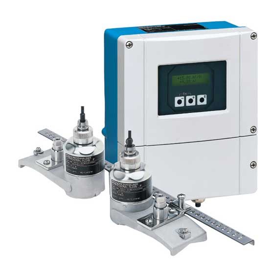
Endress+Hauser Proline Prosonic Flow 93 PROFIBUS DP/PA Operating Instructions Manual
Ultrasonic flow measuring system
Hide thumbs
Also See for Proline Prosonic Flow 93 PROFIBUS DP/PA:
- Function manual (226 pages) ,
- Operating instructions manual (162 pages) ,
- Brief operating instructions (40 pages)
Table of Contents

Related Manuals for Endress+Hauser Proline Prosonic Flow 93 PROFIBUS DP/PA


Summary of Contents for Endress+Hauser Proline Prosonic Flow 93 PROFIBUS DP/PA
- Page 1 Operating Instructions Proline Prosonic Flow 93 PROFIBUS DP/PA Ultrasonic flow measuring system BA00076D/06/EN/13.10 71121236 Valid as of version PROFIBUS DP V 3.06.XX (Device software) PROFIBUS PA V 3.06.XX (Device software)
-
Page 3: Table Of Contents
Proline Prosonic Flow 93 PROFIBUS DP/PA Table of contents Table of contents Safety instructions ....5 Installing Prosonic Flow P DN 50 to 4000 (2 to 160"), Clamp-on ..37 Designated use . - Page 4 Proline Prosonic Flow 93 PROFIBUS DP/PA Table of contents Operation ..... . 75 Acyclic data transmission PROFIBUS DP/PA . . . 128 6.8.1 Master class 2 acyclic (MS2AC) .
-
Page 5: Safety Instructions
• The device must be operated by persons authorized and trained by the facility's owner-operator. Strict compliance with the instructions in these Operating Instructions is mandatory. • Endress+Hauser is willing to assist in clarifying the chemical resistance properties of parts wetted by special fluids, including fluids used for cleaning. -
Page 6: Return
Endress+Hauser: • Always enclose a duly completed "Declaration of Contamination" form. Only then can Endress+Hauser transport, examine and repair a returned device. Note! You will find a preprinted "Declaration of Contamination" form at the back of this manual. -
Page 7: Identification
Proline Prosonic Flow 93 PROFIBUS DP/PA Identification Identification Device designation The "Prosonic Flow 93" flowmeter system consists of the following components: • Prosonic Flow 93 transmitter • Sensor: – Prosonic Flow P Clamp-on version (DN 15 to 65 / ½ to 2½") –... -
Page 8: Nameplate Of The Sensor
Reserved for information on special products Degree of protection Permitted ambient temperature range Data on explosion protection Refer to the specific additional Ex documentation for detailed information. Please do not hesitate to contact your Endress+Hauser sales office if you have any questions. Endress+Hauser... -
Page 9: Nameplate For The Connections
Proline Prosonic Flow 93 PROFIBUS DP/PA Identification 2.1.3 Nameplate for the connections active See operating manual passive Betriebsanleitung beachten normally open contact Observer manuel d'instruction normally closed contact 12345678912 Ser.No.: L1/L+ Supply / Versorgung / N/L- Tension d'alimentation 26 = B (RxD/TxD-P) 27 = A (RxD/TxD-N) PROFIBUS DP Profile 3.0... -
Page 10: Certificates And Approvals
EMC requirements of IEC/EN 61326. The measuring system described in these Operating Instructions thus complies with the statutory requirements of the EC Directives. Endress+Hauser confirms successful testing of the device by affixing to it the CE mark. The measuring system complies with the EMC requirements of the "Australian Communications and Media Authority (ACMA)". -
Page 11: Installation
Proline Prosonic Flow 93 PROFIBUS DP/PA Installation Installation Incoming acceptance, transport and storage 3.1.1 Incoming acceptance On receipt of the goods, check the following points: • Check the packaging and the contents for damage. • Check the shipment, make sure nothing is missing and that the scope of supply matches your order. -
Page 12: Orientation
Installation Proline Prosonic Flow 93 PROFIBUS DP/PA 3.2.3 Orientation Vertical orientation We recommend the sensor be mounted where there is upward direction of flow. With this orientation, entrained solids will sink down and gases will rise away from the sensor when the fluid is stagnant. -
Page 13: Sensor Selection And Arrangement
Proline Prosonic Flow 93 PROFIBUS DP/PA Installation 3.2.5 Sensor selection and arrangement The sensors can be arranged in two ways: • Mounting arrangement for measurement via one traverse: the sensors are located on opposite sides of the pipe. • Mounting arrangement for measurement via two traverses: the sensors are located on the same side of the pipe. -
Page 14: Two-Channel Operation
Installation Proline Prosonic Flow 93 PROFIBUS DP/PA Two-channel operation The transmitter is able to operate two independent measuring channels (measuring channel 1 and measuring channel 2). A pair of sensors is connected per measuring channel. Both measuring channels operate independently of one another and are supported by the transmitter to an equal extent. -
Page 15: Two-Path Measurement
Proline Prosonic Flow 93 PROFIBUS DP/PA Installation 3.3.2 Two-path measurement The flow is measured redundantly at one measuring point in the case of two-path measurement. The measured values of the two measuring channels can be processed and displayed differently. The following measured values can be output for two-path measurement: •... -
Page 16: Preparatory Steps Prior To Installation
– Local operation of the device – FieldCare (operating program), connect a notebook to the transmitter – Applicator (software), online on the Endress+Hauser Internet site Mechanical preparation of the clamp-on retainers for the sensors: – Premount the strapping bands (DN 50 to 200 / 2 to 8") or (DN 250 to 4000 / 10 to 160") –... -
Page 17: Determining Values For Installation Distances
Proline Prosonic Flow 93 PROFIBUS DP/PA Installation Determining values for installation distances 3.6.1 Determining installation distances via local operation Perform the following steps to determine the installation distances: Mount the wall-mount housing. Connect the power supply. Switch on the measuring device. - Page 18 Installation Proline Prosonic Flow 93 PROFIBUS DP/PA Panel mounting Prepare the opening in the panel → ä 18. Slide the housing into the panel cutout from the front. Screw the retainers onto the wall-mount housing. Screw the threaded rods into the retainers and tighten until the housing is solidly seated on the panel wall.
- Page 19 Connecting the power supply Warning! When connecting Ex-certified devices, please refer to the notes and diagrams in the Ex-specific supplement to these Operating Instructions. Please do not hesitate to contact your Endress+Hauser sales office if you have any questions. Note! The measuring device does not have an internal power switch.
- Page 20 Installation Proline Prosonic Flow 93 PROFIBUS DP/PA Running the "Sensor Installation" Quick Setup menu Note! • If you are not familiar with the operation of the device → ä 75. • The following section only describes the steps necessary for clamp-on and insertion type of mounting within the "Sensor Installation"...
- Page 21 Proline Prosonic Flow 93 PROFIBUS DP/PA Installation Running the Quick Setup for insertion type of mounting Enter or select installation-specific values or the values specified here. Read off the installation distances necessary for mounting. → → Setup sensor Home position Quick Setup ↓...
-
Page 22: Via Fieldcare
Proline Prosonic Flow 93 PROFIBUS DP/PA 3.6.2 Determining installation distances via FieldCare FieldCare is Endress+Hauser’s FDT-based plant asset management tool and allows the configuration and diagnosis of intelligent field devices. The Proline flowmeters are accessed via a service interface or via the service interface FXA193. - Page 23 Proline Prosonic Flow 93 PROFIBUS DP/PA Installation Panel mounting Prepare the opening in the panel → ä 23. Slide the housing into the panel cutout from the front. Screw the retainers onto the wall-mount housing. Screw the threaded rods into the retainers and tighten until the housing is solidly seated on the panel wall.
- Page 24 Connecting the power supply Warning! When connecting Ex-certified devices, please refer to the notes and diagrams in the Ex-specific supplement to these Operating Instructions. Please do not hesitate to contact your Endress+Hauser sales office if you have any questions. Note! The measuring device does not have an internal power switch.
- Page 25 Proline Prosonic Flow 93 PROFIBUS DP/PA Installation Connecting the PC to the plant asset management tool A personal computer is connected to the FieldCare plant asset management tool via the service interface FXA 193. The service interface FXA 193 is connected to the service connector of the transmitter.
- Page 26 Installation Proline Prosonic Flow 93 PROFIBUS DP/PA Basic function ↓ → Process parameter K1/K2 Pipe data ↓ Pipe standard Nominal diameter Pipe material Sound velocity pipe Circumference Pipe diameter Wall thickness Liner material Basic function ↓ → Process parameter K1/K2 Liquid data ↓...
- Page 27 Proline Prosonic Flow 93 PROFIBUS DP/PA Installation Reading off installation distances via FieldCare for insertion type of mounting Enter or select installation-specific values or the values specified here. Read off the installation distances necessary for mounting. Basic function ↓ →...
-
Page 28: Via Applicator
Installation Proline Prosonic Flow 93 PROFIBUS DP/PA 3.6.3 Determining installation distances via Applicator Applicator is a software application for selecting and planning flowmeters. The installation distances required for installation can be determined without having to commission the transmitter beforehand. Applicator is available: •... - Page 29 Proline Prosonic Flow 93 PROFIBUS DP/PA Installation Determining installation distances for insertion version, dual-path measurement Determine the installation distances required via Applicator: • Select the fluid. • Select the device (e.g. 93W Insert 2Ch). • Enter or select measuring point-specific values.
-
Page 30: Mechanical Preparation
Installation Proline Prosonic Flow 93 PROFIBUS DP/PA Mechanical preparation The way in which the sensors are secured differs on account of the pipe nominal diameter and the sensor type. Depending on the type of sensor, users also have the option of securing the sensors with strapping bands or screws such that they can be later removed, or permanently fixing the sensors in place with welded bolts or welded retainers. -
Page 31: With Strapping Bands
Proline Prosonic Flow 93 PROFIBUS DP/PA Installation 3.7.2 Mounting the sensor holder with strapping bands For mounting on a pipe with a nominal diameter of DN > 32 (1¼") For sensors: • Prosonic Flow 93P (DN 15 to 65 / ½ to 2½") Procedure Disconnect the sensor from the sensor holder. -
Page 32: Premounting The Strapping Bands (Medium Nominal Diameters)
Installation Proline Prosonic Flow 93 PROFIBUS DP/PA 3.7.3 Premounting the strapping bands (medium nominal diameters) When mounting on a pipe with a nominal diameter of DN ≤ 200 (8") For sensors: • Prosonic Flow 93P (DN 50 to 4000 / 2 to 160") •... -
Page 33: Premounting The Strapping Bands (Large Nominal Diameters)
Proline Prosonic Flow 93 PROFIBUS DP/PA Installation 3.7.4 Premounting the strapping bands (large nominal diameters) When mounting on a pipe with a nominal diameter of DN > 200 (8") For sensors: • Prosonic Flow 93P (DN 50 to 4000 / 2 to 160") •... -
Page 34: Mounting The Welded Bolts
Installation Proline Prosonic Flow 93 PROFIBUS DP/PA 3.7.5 Mounting the welded bolts When mounting on a pipe with a nominal diameter of DN 50 to 4000 (2 to 160") For sensors: • Prosonic Flow 93P (DN 50 to 4000 / 2 to 160") •... -
Page 35: Installing Prosonic Flow Pdn 15 To 65 (½ To 2½")
Proline Prosonic Flow 93 PROFIBUS DP/PA Installation Installing Prosonic Flow P DN 15 to 65 (½ to 2½") 3.8.1 Mounting the sensor Prerequisites • The installation distance (sensor distance) is known → ä 16. • The sensor holder is already mounted → ä 30. - Page 36 Installation Proline Prosonic Flow 93 PROFIBUS DP/PA Fix the sensor housing with the bracket. Note! – If necessary, the holder and sensor housing can be secured with a screw/nut or a lead-seal (not part of the scope of supply). – The bracket can only be released using an auxiliary tool.
-
Page 37: Installing Prosonic Flow Pdn 50 To 4000 (2 To 160"), Clamp-On
Proline Prosonic Flow 93 PROFIBUS DP/PA Installation Installing Prosonic Flow P DN 50 to 4000 (2 to 160"), Clamp-on 3.9.1 Installation for measurement via one traverse Prerequisites • The installation distances (sensor distance and wire length) are known → ä 16. - Page 38 Installation Proline Prosonic Flow 93 PROFIBUS DP/PA Loosen the screws of the fixers on the measuring wires and remove the measuring wires from the mounting bolt. Fit the sensor holders over the individual mounting bolts and tighten securely with the retaining nut.
-
Page 39: Via Two Traverses
Proline Prosonic Flow 93 PROFIBUS DP/PA Installation 3.9.2 Installation for measurement via two traverses Prerequisites • The installation distance (position sensor) is known → ä 16. • The strapping bands are already mounted → ä 30. Material The following material is needed for mounting: •... - Page 40 Installation Proline Prosonic Flow 93 PROFIBUS DP/PA A0001156 Fig. 34: Mounting the sensor holders and mounting rail Coat the contact surfaces of the sensors with an even layer of coupling fluid approx. 1 mm (0.04") thick, going from the groove through the center to the opposite edge.
-
Page 41: Installing Prosonic Flow W (Clamp-On)
Proline Prosonic Flow 93 PROFIBUS DP/PA Installation 3.10 Installing Prosonic Flow W (Clamp-on) 3.10.1 Installation for measurement via one traverse Prerequisites • The installation distances (sensor distance and wire length) are known → ä 16. • The strapping bands are already mounted → ä 30. - Page 42 Installation Proline Prosonic Flow 93 PROFIBUS DP/PA Loosen the screws of the fixers on the measuring wires and remove the measuring wires from the mounting bolt. Fit the sensor holders over the individual mounting bolts and tighten securely with the retaining nut.
-
Page 43: Via Two Traverses
Proline Prosonic Flow 93 PROFIBUS DP/PA Installation 3.10.2 Installation for measurement via two traverses Prerequisites • The installation distance (position sensor) is known → ä 16. • The strapping bands are already mounted → ä 30. Material The following material is needed for mounting: •... - Page 44 Installation Proline Prosonic Flow 93 PROFIBUS DP/PA A0001117 Fig. 43: Mounting the sensor Coat the contact surfaces of the sensors with an even layer of coupling fluid approx. 1 mm (0.04") thick, going from the groove through the center to the opposite edge.
-
Page 45: Installing Prosonic Flow W (Insertion Version)
Proline Prosonic Flow 93 PROFIBUS DP/PA Installation 3.11 Installing Prosonic Flow W (Insertion version) The graphic below provides you with an overview of the terms used when installing a Prosonic Flow W (Insertion version). α α A0013926 Fig. 46: Explanation of terms... -
Page 46: Installation For Measurement As Single-Path Insertion Version
Installation Proline Prosonic Flow 93 PROFIBUS DP/PA 3.11.1 Installation for measurement as single-path insertion version Determine the installation area (e) on the pipe section: – Mounting location → ä 11 – Inlet/outlet run → ä 12 – Space required by the measuring point: approx. 1× pipe diameter. - Page 47 Proline Prosonic Flow 93 PROFIBUS DP/PA Installation Project the middle line to the back of the pipe and draw it on. A0001126 Fig. 49: Installing the measuring sensors, steps 5 and 6 Mark the drillhole on the middle line on the back of the pipe.
- Page 48 Installation Proline Prosonic Flow 93 PROFIBUS DP/PA 11. Weld in both sensor holders. 12. Check the distance between the drillholes once again and determine the path length. Note! Determine the path length as follows: – Via the Quick Setup "Sensor Installation" for measuring devices with local operation.
-
Page 49: Installation For Measurement As Dual-Path Insertion Version
Proline Prosonic Flow 93 PROFIBUS DP/PA Installation 3.11.2 Installation for measurement as dual-path insertion version Determine the installation area (e) on the pipe section: – Mounting location → ä 11 – Inlet/outlet run → ä 12 – Space required by the measuring point: approx. 1× pipe diameter. - Page 50 Installation Proline Prosonic Flow 93 PROFIBUS DP/PA You can correct the middle line with the arc length determined. A0001163 Fig. 55: Installing the dual-path measuring sensors, steps 5 and 6 Project the corrected middle line onto the other side of the pipe and draw this on (half pipe circumference).
- Page 51 Proline Prosonic Flow 93 PROFIBUS DP/PA Installation 11. Insert the sensor holders into the first pair of drillholes and align with the tie rod (alignment tool). Spot-weld with the wedding apparatus and then permanently weld both sensor holders. Note! To align the tie rod, two guide bushings must be screwed onto the sensor holders.
- Page 52 Installation Proline Prosonic Flow 93 PROFIBUS DP/PA 15. Then screw the sensors into the sensor holders by hand. If you use a tool, the maximum torque permissible is 30 Nm. 16. Insert the sensor cable connectors into the opening provided and manually tighten the connectors to the stop.
-
Page 53: Installing Sensor Ddu18
Proline Prosonic Flow 93 PROFIBUS DP/PA Installation 3.12 Installing sensor DDU18 Premount the strapping band: – Nominal diameters DN ≤ 200 (8") → ä 32 – Nominal diameters DN > 200 (8") → ä 33 The two mounting bolts must be positioned opposite each other on either side of the pipe. -
Page 54: Installing Sensor Ddu19
Installation Proline Prosonic Flow 93 PROFIBUS DP/PA 3.13 Installing sensor DDU19 3.13.1 Version 1 Premount the strapping band: – Nominal diameters DN ≤ 200 (8") → ä 32 – Nominal diameters DN > 200 (8") → ä 33 The two mounting bolts must be positioned opposite each other on either side of the pipe. -
Page 55: Installing The Wall-Mount Transmitter Housing
Proline Prosonic Flow 93 PROFIBUS DP/PA Installation 3.14 Installing the wall-mount transmitter housing There are various ways of installing the wall-mount housing: • Direct wall mounting • Panel mounting (with separate mounting kit, accessories → ä 132) • Pipe mounting (with separate mounting kit, accessories → ä 132) "... -
Page 56: Panel Mounting
Installation Proline Prosonic Flow 93 PROFIBUS DP/PA 3.14.2 Panel mounting Prepare the opening in the panel → å 65. Slide the housing into the panel cutout from the front. Screw the retainers onto the wall-mount housing. Screw the threaded rods into the retainers and tighten until the housing is solidly seated on the panel wall. -
Page 57: Post-Installation Check
Proline Prosonic Flow 93 PROFIBUS DP/PA Installation 3.15 Post-installation check Perform the following checks after installing the measuring device on the pipe: Device condition and specifications Notes Is the device damaged (visual inspection)? – → ä 158 Does the device correspond to specifications at the measuring point, including process temperature, ambient temperature, measuring range, etc.? -
Page 58: Wiring
Wiring Warning! When connecting Ex-certified devices, please refer to the notes and diagrams in the Ex-specific supplement to these Operating Instructions. Please do not hesitate to contact your Endress+Hauser sales office if you have any questions. Note! The device does not have an internal power switch. For this reason, assign the device a switch or power-circuit breaker which can be used to disconnect the power supply line from the power grid. - Page 59 Proline Prosonic Flow 93 PROFIBUS DP/PA Wiring Example In accordance with manufacturer specifications, 9 repeaters can be switched in series when using a standard line. The maximum distance between two bus users at a transmission rate of 1.5 MBit/s can be calculated as follows: (9 + 1) x 200 m (660 ft) = 2000 m (6600 ft).
-
Page 60: Profibus Pa Cable Specifications
Wiring Proline Prosonic Flow 93 PROFIBUS DP/PA 4.1.2 PROFIBUS PA cable specifications Cable type Twin-core cables are recommended for connecting the device to the fieldbus. Following IEC 61158-2 (MBP), four different cable types (A, B, C, D) can be used with the fieldbus, only two of which (cable types A and B) are shielded. - Page 61 Proline Prosonic Flow 93 PROFIBUS DP/PA Wiring Maximum spur length The line between the distribution box and field device is described as a spur. In the case of non-Ex applications, the max. length of a spur depends on the number of spurs >1 m (>3.28 ft):...
-
Page 62: Shielding And Grounding
Wiring Proline Prosonic Flow 93 PROFIBUS DP/PA 4.1.3 Shielding and grounding When planning the shielding and grounding for a fieldbus system, there are three important points to consider: • Electromagnetic compatibility (EMC) • Explosion protection • Safety of the personnel... -
Page 63: Connecting Prosonic Flow W And Pdn 50 To 4000 (2 To 160")
Proline Prosonic Flow 93 PROFIBUS DP/PA Wiring 4.2.1 Connecting Prosonic Flow W and P DN 50 to 4000 (2 to 160") Procedure → ä 64 Remove the cover (a) of the connection compartment. Remove the dummy cover from the cable entry (b). - Page 64 Wiring Proline Prosonic Flow 93 PROFIBUS DP/PA A0008654 Fig. 67: Connecting the connecting cable for sensor/transmitter (with cable gland for two connecting cables per cable entry) View A Detail B Sensor cable connector, channel 1 upstream Sensor cable connector, channel 1 downstream...
-
Page 65: Grounding Prosonic Flow Pdn 15 To 65 (½ To 2½")
4.2.3 Cable specification for connecting cable Only use the connecting cables supplied by Endress+Hauser. The connecting cables are available in different lengths → ä 132 ff. For the cable specifications, see → ä 154. -
Page 66: Connecting The Measuring Unit
Wiring Proline Prosonic Flow 93 PROFIBUS DP/PA Connecting the measuring unit 4.3.1 Terminal assignment Electrical values for: • Inputs → ä 152 • Outputs → ä 153 PROFIBUS DP " Caution! Only certain combinations of submodules (see Table) on the I/O board are permissible. The... -
Page 67: Connecting The Transmitter
Proline Prosonic Flow 93 PROFIBUS DP/PA Wiring 4.3.2 Connecting the transmitter Warning! • Risk of electric shock. Switch off the power supply before opening the device. Do not install or wire the device while it is connected to the power supply. Failure to comply with this precaution can result in irreparable damage to the electronics. -
Page 68: Profibus Dp Connection Diagram
Wiring Proline Prosonic Flow 93 PROFIBUS DP/PA 4.3.3 PROFIBUS DP connection diagram Permanent assignment board (order version 93***-***********J) +5 V N (L–) DGND L1 (L+) B (RxD/TxD-P) A (RxD/TxD-N) 20 21 22 23 24 25 26 27 A0014363 Fig. 68: Connecting the transmitter, cable cross-section max. - Page 69 Proline Prosonic Flow 93 PROFIBUS DP/PA Wiring Flexible assignment boards (order version 93***-***********V and 93***-***********P) N (L–) L1 (L+) B (RxD/TxD-P) A (RxD/TxD-N) 20 21 22 23 24 25 26 27 A0014364 Fig. 69: Connecting the transmitter, cable cross-section: max. 2.5 mm...
-
Page 70: Profibus Pa Connection Diagram
Wiring Proline Prosonic Flow 93 PROFIBUS DP/PA 4.3.4 PROFIBUS PA connection diagram Flexible assignment boards (order version 93***-***********F and 93***-***********H) N (L–) L1 (L+) PA (+) PA (–) 20 21 22 23 24 25 26 27 A0014365 Fig. 70: Connecting the transmitter, cable cross-section: max. 2.5 mm... - Page 71 4-channel or 8-channel distribution modules. The device can therefore be supplied with the option of a ready-mounted fieldbus connector. Fieldbus connectors for retrofitting can be ordered from Endress+Hauser as a spare part → ä 132. 150/300 45.0 (1.77) (5.91/11.81)
- Page 72 Wiring Proline Prosonic Flow 93 PROFIBUS DP/PA Technical data (fieldbus connector): Connection cross section 0.75 mm (0.0012 in²) Connector thread PG 13.5 Degree of protection IP 67 in accordance with DIN 40 050 IEC 529 Contact surface CuZnAu Housing material...
-
Page 73: Degree Of Protection
Compliance with the following points is mandatory following installation in the field or servicing, in order to ensure that IP 67/68 protection is maintained: • Only use connecting cables supplied by Endress+Hauser with the corresponding cable connectors. • When connecting, do not jam the cable connectors. Tighten them to the stop. -
Page 74: Post-Connection Check
Wiring Proline Prosonic Flow 93 PROFIBUS DP/PA Post-connection check Perform the following checks after completing electrical installation of the measuring device: Device condition and specifications Notes Are cables or the device damaged (visual inspection)? Electrical connection Notes Does the supply voltage match the specifications on the nameplate? -
Page 75: Operation
Proline Prosonic Flow 93 PROFIBUS DP/PA Operation Operation Quick operation guide You have a number of options for configuring and commissioning the device: Local display (option) → ä 76 The local display enables you to read all important variables directly at the measuring point, configure device-specific parameters in the field and perform commissioning. -
Page 76: Local Display
Operation Proline Prosonic Flow 93 PROFIBUS DP/PA Local display 5.2.1 Display and operating elements The local display enables you to read all important parameters directly at the measuring point and configure the device using the "Quick Setup" or the function matrix. -
Page 77: Display (Operating Mode)
Proline Prosonic Flow 93 PROFIBUS DP/PA Operation 5.2.2 Display (operating mode) The display area consists of three lines in all; this is where measured values are displayed, and/or status variables (direction of flow, bar graph, etc.). You can change the assignment of display lines to different variables to suit your needs and preferences (→... -
Page 78: Icons
Operation Proline Prosonic Flow 93 PROFIBUS DP/PA 5.2.4 Icons The icons which appear in the field on the left make it easier to read and recognize measured variables, device status, and error messages. Icon Meaning Icon Meaning System error Process error... -
Page 79: Brief Guide To The Function Matrix
Proline Prosonic Flow 93 PROFIBUS DP/PA Operation Brief guide to the function matrix Note! • See the general notes → ä 80 • Function descriptions → see the "Description of Device Functions" manual" HOME position → F → Entry into the function matrix O / S →... -
Page 80: General Notes
• If programming is disabled and the OS operating elements are pressed in any function, a prompt for the code automatically appears on the display. • If "0" is entered as the private code, programming is always enabled. • The Endress+Hauser service organization can be of assistance if you mislay your personal code. " Caution! Changing certain parameters such as all sensor characteristics, for example, influences numerous functions of the entire measuring system, particularly measuring accuracy. -
Page 81: Error Messages
Proline Prosonic Flow 93 PROFIBUS DP/PA Operation Error messages 5.4.1 Type of error Errors that occur during commissioning or measuring are displayed immediately. If two or more system or process errors occur, the error with the highest priority is the one shown on the display. -
Page 82: Operating Options
5.5.1 Operating program "FieldCare" FieldCare is Endress+Hauser’s FDT-based plant asset management tool and allows the configuration and diagnosis of intelligent field devices. By using status information, you also have a simple but effective tool for monitoring devices. The Proline flowmeters are accessed via a service interface or via the service interface FXA193. - Page 83 The Fieldcheck tester/simulator is used for testing flowmeters in the field. When used in conjunction with the "FieldCare" software package, test results can be imported into a database, printed and used for official certification. Contact your Endress+Hauser representative for more information.
-
Page 84: Profibus Dp Hardware Settings
Operation Proline Prosonic Flow 93 PROFIBUS DP/PA PROFIBUS DP hardware settings 5.6.1 Configuring the write protection A jumper on the I/O board provides the means of switching hardware write protection on or off. When hardware write protection is switched on, it is not possible to write to the device functions via PROFIBUS (acyclic data transmission, e.g. -
Page 85: Configuring The Device Address
Proline Prosonic Flow 93 PROFIBUS DP/PA Operation 5.6.2 Configuring the device address The address must always be configured for a PROFIBUS DP/PA device. Valid device addresses are in the range 1 to 126. Any address can only be allocated once in a PROFIBUS DP/PA network. If an address is not configured correctly, the device is not recognized by the master. -
Page 86: Configuring The Terminating Resistors
Operation Proline Prosonic Flow 93 PROFIBUS DP/PA 5.6.3 Configuring the terminating resistors Note! It is important to terminate the RS485 line correctly at the start and end of the bus segment since impedance mismatch results in reflections on the line which can cause faulty communication transmission. -
Page 87: Profibus Pa Hardware Settings
Proline Prosonic Flow 93 PROFIBUS DP/PA Operation PROFIBUS PA hardware settings 5.7.1 Configuring the write protection A jumper on the I/O board provides the means of switching hardware write protection on or off. When hardware write protection is switched on, it is not possible to write to the device functions via PROFIBUS (acyclic data transmission, e.g. -
Page 88: Configuring The Device Address
Operation Proline Prosonic Flow 93 PROFIBUS DP/PA 5.7.2 Configuring the device address The address must always be configured for a PROFIBUS PA device. Valid device addresses are in the range 1 to 126. Any address can only be allocated once in a PROFIBUS network. If an address is not configured correctly, the device is not recognized by the master. -
Page 89: Commissioning
Proline Prosonic Flow 93 PROFIBUS DP/PA Commissioning Commissioning Function check Make sure that the following function checks have been performed successfully before switching on the supply voltage for the measuring device: • Checklist for "Post-installation check" → ä 57 • Checklist for "Post-connection check" → ä 74... -
Page 90: Quick Setup
Commissioning Proline Prosonic Flow 93 PROFIBUS DP/PA Quick Setup In the case of measuring devices without a local display, the individual parameters and functions must be configured via the operating program, e.g. FieldCare. If the measuring device is equipped with a local display, all the important device parameters for standard operation, as well as additional functions, can be configured quickly and easily by means of the following Quick Setup menus. - Page 91 Proline Prosonic Flow 93 PROFIBUS DP/PA Commissioning Note! The display returns to the cell SETUP SENSOR (1001) if you press the X key combination during parameter interrogation. The stored parameters remain valid. The choice of system units only influences the functions UNIT TEMPERATURE (0422), UNIT LENGTH (0424) and UNIT VELOCITY (0425).
-
Page 92: Quick Setup "Commissioning
Commissioning Proline Prosonic Flow 93 PROFIBUS DP/PA 6.3.2 Quick Setup "Commissioning" 1002 XXX.XXX.XX Quick Setup Commission. 2000 HOME-POSITION Language Presetting Selection pre-settings Deliver Settings Actual Settings Selection system units System Units Volume Temperature Viscosity Length Velocity Quit 0402 0422 0423... -
Page 93: Quick Setup "Communication
Proline Prosonic Flow 93 PROFIBUS DP/PA Commissioning 6.3.3 Quick Setup "Communication" To establish cyclic data transfer, various arrangements between the PROFIBUS master (Class 1) and the measuring device (slave) are required which have to be taken into consideration when configuring various functions. These functions can be configured quickly and easily by means of the "Communication"... - Page 94 Commissioning Proline Prosonic Flow 93 PROFIBUS DP/PA Quick Setup "Communication" 6141 UNIT TO BUS If this function is executed, the measured variables are transmitted cyclically to the PROFIBUS master (Class 1) with the system units set in the measuring device.
-
Page 95: Data Backup/Transmission
Proline Prosonic Flow 93 PROFIBUS DP/PA Commissioning 6.3.4 Data backup/transmission Using the T-DAT SAVE/LOAD function, you can transfer data (device parameters and settings) between the T-DAT (exchangeable memory) and the EEPROM (device storage unit). This is required in the following instances: •... -
Page 96: Commissioning The Profibus Interface
Commissioning Proline Prosonic Flow 93 PROFIBUS DP/PA Commissioning the PROFIBUS interface Note! • All functions required for commissioning are described in detail in the "Description of Device Functions" manual which is a separate part of these Operating Instructions. • A code (factory setting: 93) must be entered to change device functions, numerical values or factory settings →... - Page 97 Proline Prosonic Flow 93 PROFIBUS DP/PA Commissioning Configuration of the Analog Input function blocks 1 to 8: The measuring device has eight Analog Input function blocks (AI modules) via which the various measured variables can be cyclically transmitted to the PROFIBUS master (Class 1).
- Page 98 Commissioning Proline Prosonic Flow 93 PROFIBUS DP/PA Configuration of totalizers 1 to 3: The measuring device has three totalizers. The following example describes the configuration of the totalizer using totalizer 1 as an example. • Using the CHANNEL function (6133), you can determine the measured variable (e.g. mass flow) to be transmitted to the PROFIBUS master (Class 1) as a totalizer value: a.
-
Page 99: Profibus Pa Commissioning
Proline Prosonic Flow 93 PROFIBUS DP/PA Commissioning Select the operating mode: Select the operating mode (GSD file) which should be used for cyclic communication with the PROFIBUS master (Class 1). BASIC FUNCTION (G) → PROFIBUS DP (GBA) → OPERATION (614) →... - Page 100 Commissioning Proline Prosonic Flow 93 PROFIBUS DP/PA Note! • The configuration of the system units for the totalizer is described separately → see step 7 • If the system unit of a measured variable is changed by means of the local operation or an operating program, this initially does not have any effect on the unit that is used to transmit the measured variable to the PROFIBUS master (Class 1).
- Page 101 Proline Prosonic Flow 93 PROFIBUS DP/PA Commissioning BASIC FUNCTION (G) → SYSTEM PARAMETER (GLA) → CONFIGURATION (660) → MEASURING MODE (6601) → Selection of one of the following options: – UNIDIRECTIONAL (factory setting) = only the positive flow portions – BIDIRECTIONAL = the positive and negative flow components Configuration of totalizers 1 to 3: The measuring device has three totalizers.
- Page 102 Commissioning Proline Prosonic Flow 93 PROFIBUS DP/PA Select the operating mode: Select the operating mode (GSD file) which should be used for cyclic communication with the PROFIBUS master (Class 1). BASIC FUNCTION (G) → PROFIBUS PA (GCA) → OPERATION (614) →...
-
Page 103: Profibus Dp/Pa System Integration
How to acquire • Internet (Endress+Hauser) → www.endress.com → Download • CD-ROM with all GSD files for Endress+Hauser devices → Order No.: 56003894 Contents of the download file from the Internet and the CD-ROM: • All Endress+Hauser GSD files (standard and extended format) •... - Page 104 The Profibus User Organization (PNO) gives each device an identification number (ID No.). The name of the GSD file is derived from this number. For Endress+Hauser, this ID No. starts with the manufacturer ID 15xx. To clarify the assignment of the GSD files, the GSD names (apart from the Type files) at...
-
Page 105: Selecting The Gsd File In The Measuring Device
Proline Prosonic Flow 93 PROFIBUS DP/PA Commissioning 6.5.2 Selecting the GSD file in the measuring device Depending on which GSD file is used in the PROFIBUS master system, the corresponding GSD file has to be configured in the device by means of the SELECTION GSD function. -
Page 106: Cyclic Data Transmission Profibus Dp
Commissioning Proline Prosonic Flow 93 PROFIBUS DP/PA Cyclic data transmission PROFIBUS DP Below is a description of the cyclic data transmission when using the Prosonic Flow 93 GSD file (complete device functionality). 6.6.1 Block model The block model illustrated shows which input and output data Prosonic Flow 93 provides for cyclic data exchange via PROFIBUS DP. - Page 107 Proline Prosonic Flow 93 PROFIBUS DP/PA Commissioning It is essential to adhere to the following sequence/assignment when configuring the modules in the PROFIBUS master system: Slot Module Description sequence Analog Input function block 1 Output variable → volume flow channel 1 (factory setting) Analog Input function block 2 Output variable →...
-
Page 108: Description Of The Modules
Commissioning Proline Prosonic Flow 93 PROFIBUS DP/PA 6.6.3 Description of the modules AI module (Analog Input) The corresponding measured variable, including the status, is cyclically transmitted to the PROFIBUS master (Class 1) by means of the AI module (slots 1 to 8). The measured variable is represented in the first four bytes in the form of a floating point number in accordance with the IEEE 754 standard. - Page 109 Proline Prosonic Flow 93 PROFIBUS DP/PA Commissioning Factory setting: Module Analog Measured variable Unit ID for Input CHANNEL function function block AI (slot 1) VOLUME FLOW CHANNEL 1 m³/h AI (slot 2) SOUND VELOCITY CHANNEL 1 AI (slot 3) FLOW VELOCITY CHANNEL 1...
- Page 110 Commissioning Proline Prosonic Flow 93 PROFIBUS DP/PA Possible settings Possible settings Totalizer value/measured variable (channel 1 = active) ID for CHANNEL function VOLUME FLOW CHANNEL 1 (factory setting totalizer 1 to 3) Totalizer value/measured variable (channel 1 + channel 2 =...
- Page 111 Proline Prosonic Flow 93 PROFIBUS DP/PA Commissioning TOTAL function For a description of the TOTAL function, refer to TOTAL module → ä 109. Data structure of the SETTOT_TOTAL module combination Output data Input data SETTOT TOTAL Byte 1 Byte 1...
- Page 112 Commissioning Proline Prosonic Flow 93 PROFIBUS DP/PA DISPLAY_VALUE module Any value (IEEE 754 floating point number), including status, can be cyclically transmitted via the PROFIBUS master (Class 1) directly to the local display using the DISPLAY_VALUE module (slot 10). Display value assignment to the main line, additional line or info line can be configured via the local display itself or an operating program (e.g.
- Page 113 Proline Prosonic Flow 93 PROFIBUS DP/PA Commissioning Output data Byte 1 Control EMPTY_MODULE module The measuring device is a so-called modular PROFIBUS slave. In contrast to a compact slave, the structure of a modular slave is variable - it consists of several individual modules. In the GSD file, the individual modules are described with their individual properties.
-
Page 114: Configuration Examples With Simatic S7 Hw-Konfig
Commissioning Proline Prosonic Flow 93 PROFIBUS DP/PA 6.6.4 Configuration examples with Simatic S7 HW-Konfig Example 1: A0008802 Fig. 89: Complete configuration using the Prosonic Flow 93 GSD file It is essential to adhere to the following sequence when configuring the modules in the... - Page 115 Proline Prosonic Flow 93 PROFIBUS DP/PA Commissioning Slot Byte length Byte length Module Description sequence input data output data Totalizer function block 2 TOTAL → output variable = totalized mass flow (factory setting) SETTOT_MODETOT_TOTAL SETTOT→ totalizer control MODETOT → totalizer configuration Totalizer function block 3 TOTAL →...
- Page 116 Commissioning Proline Prosonic Flow 93 PROFIBUS DP/PA Example 2: A0008803 Fig. 90: In this configuration example, modules that are not needed are replaced by the module EMPTY_MODULE. The Promass Flow 93 GSD file is used. With this configuration, the Analog Input function block 1 (slot 1), the totalizer value TOTAL (slot 9) and the cyclic control of device functions CONTROL_BLOCK (slot 13) are activated.
-
Page 117: Cyclic Data Transmission Profibus Pa
Proline Prosonic Flow 93 PROFIBUS DP/PA Commissioning Cyclic data transmission PROFIBUS PA Below is a description of the cyclic data transmission when using the Prosonic Flow 93 GSD file (complete device functionality). 6.7.1 Block model The block model illustrated shows which input and output data Prosonic Flow 93 provides for cyclic data exchange via PROFIBUS PA. - Page 118 Commissioning Proline Prosonic Flow 93 PROFIBUS DP/PA It is essential to adhere to the following sequence/assignment when configuring the modules in the PROFIBUS master system: Slot Module Description sequence Analog Input function block 1 Output variable → volume flow channel 1 (factory setting) Analog Input function block 2 Output variable →...
-
Page 119: Description Of The Modules
Proline Prosonic Flow 93 PROFIBUS DP/PA Commissioning 6.7.3 Description of the modules AI module (Analog Input) The corresponding measured variable, including the status, is cyclically transmitted to the PROFIBUS master (Class 1) by means of the AI module (slots 1 to 8). The measured variable is represented in the first four bytes in the form of a floating point number in accordance with the IEEE 754 standard. - Page 120 Commissioning Proline Prosonic Flow 93 PROFIBUS DP/PA Factory setting: Module Analog Measured variable Unit ID for Input CHANNEL function function block AI (slot 1) VOLUME FLOW CHANNEL 1 m³/h AI (slot 2) SOUND VELOCITY CHANNEL 1 AI (slot 3) FLOW VELOCITY CHANNEL 1...
- Page 121 Proline Prosonic Flow 93 PROFIBUS DP/PA Commissioning Possible settings Possible settings Totalizer value/measured variable (channel 1 = active) ID for CHANNEL function VOLUME FLOW CHANNEL 1 (factory setting totalizer 1 to 3) Totalizer value/measured variable (channel 1 + channel 2 =...
- Page 122 Commissioning Proline Prosonic Flow 93 PROFIBUS DP/PA TOTAL function For a description of the TOTAL function, refer to TOTAL module → ä 109. Data structure of the SETTOT_TOTAL module combination Output data Input data SETTOT TOTAL Byte 1 Byte 1...
- Page 123 Proline Prosonic Flow 93 PROFIBUS DP/PA Commissioning DISPLAY_VALUE module Any value (IEEE 754 floating point number), including status, can be cyclically transmitted via the PROFIBUS master (Class 1) directly to the local display using the DISPLAY_VALUE module (slot 10). Display value assignment to the main line, additional line or info line can be configured via the local display itself or an operating program (e.g.
- Page 124 Commissioning Proline Prosonic Flow 93 PROFIBUS DP/PA Output data Byte 1 Control EMPTY_MODULE module The measuring device is a so-called modular PROFIBUS slave. In contrast to a compact slave, the structure of a modular slave is variable - it consists of several individual modules. In the GSD file, the individual modules are described with their individual properties.
-
Page 125: Configuration Examples With Simatic S7 Hw-Konfig
Proline Prosonic Flow 93 PROFIBUS DP/PA Commissioning 6.7.4 Configuration examples with Simatic S7 HW-Konfig Example 1: A0008802 Fig. 92: Complete configuration using the Prosonic Flow 93 GSD file It is essential to adhere to the following sequence when configuring the modules in the... - Page 126 Commissioning Proline Prosonic Flow 93 PROFIBUS DP/PA Slot Byte length Byte length Module Description sequence input data output data Totalizer function block 2 TOTAL → output variable = totalized mass flow (factory setting) SETTOT_MODETOT_TOTAL SETTOT→ totalizer control MODETOT → totalizer configuration Totalizer function block 3 TOTAL →...
- Page 127 Proline Prosonic Flow 93 PROFIBUS DP/PA Commissioning Example 2: A0008803 Fig. 93: In this configuration example, modules that are not needed are replaced by the module EMPTY_MODULE. The Promass Flow 93 GSD file is used. With this configuration, the Analog Input function block 1 (slot 1), the totalizer value TOTAL (slot 9) and the cyclic control of device functions CONTROL_BLOCK (slot 13) are activated.
-
Page 128: Acyclic Data Transmission Profibus Dp/Pa
Commissioning Proline Prosonic Flow 93 PROFIBUS DP/PA Acyclic data transmission PROFIBUS DP/PA Acyclic data transmission is used to transmit parameters during commissioning or maintenance, or to display additional measured variables that are not included in cyclic data traffic. Thus parameters... -
Page 129: Adjustment
In instances of this nature, please contact your Endress+Hauser service center. • You can view the currently valid zero point value using the ZERO POINT function (see the "Description of Device Functions"... -
Page 130: Memory (Historom)
6.10 Memory (HistoROM) At Endress+Hauser, the term HistoROM refers to various types of data storage modules on which process and measuring device data are stored. By plugging and unplugging such modules, device configurations can be duplicated onto other measuring devices to cite just one example. -
Page 131: Maintenance
Proline Prosonic Flow 93 PROFIBUS DP/PA Maintenance Maintenance The flow measuring system Prosonic Flow 93 PROFIBUS DP/PA requires no special maintenance. Exterior cleaning When cleaning the exterior of measuring devices, always use cleaning agents that do not attack the surface of the housing and the seals. -
Page 132: Accessories
Accessories Proline Prosonic Flow 93 PROFIBUS DP/PA Accessories Various accessories, which can be ordered separately from Endress+Hauser, are available for the transmitter and the sensor. The Endress+Hauser service organization can provide detailed information on the order codes on request. Device-specific accessories... - Page 133 Proline Prosonic Flow 93 PROFIBUS DP/PA Accessories Measuring principle-specific accessories Accessory Description Order code Mounting kit for Mounting kit for wall-mount housing. DK9WM - A aluminum field housing Suitable for: • Wall mounting • Pipe mounting • Panel mounting Mounting kit for field...
- Page 134 Accessories Proline Prosonic Flow 93 PROFIBUS DP/PA Service-specific accessories Accessory Description Order code Applicator Software for selecting and planning flowmeters. DXA80 – * The Applicator can be downloaded from the Internet or ordered on CD-ROM for installation on a local PC.
-
Page 135: Troubleshooting
Proline Prosonic Flow 93 PROFIBUS DP/PA Troubleshooting Troubleshooting Troubleshooting instructions Always start troubleshooting with the following checklist if faults occur after commissioning or during operation. The routine takes you directly to the cause of the problem and the appropriate remedial measures. - Page 136 Troubleshooting Proline Prosonic Flow 93 PROFIBUS DP/PA Fieldbus voltage Check that a min. bus voltage of 9 V DC is present at terminals 26/27. (only for PROFIBUS PA) Permissible range: 9 to 32 V DC Check permissible fieldbus length and number of spurs. → ä 58...
-
Page 137: System Error Messages
Caution! In the event of a serious fault, a flowmeter might have to be returned to the manufacturer for repair. Important procedures must be carried out before you return a flowmeter to Endress+Hauser → ä 6. Always enclose a duly completed "Declaration of Contamination" form. A copy of the form can be... -
Page 138: List Of System Error Messages
Troubleshooting Proline Prosonic Flow 93 PROFIBUS DP/PA • For FAILSAFE_TYPE→ LAST GOOD (factory setting): If a valid output value was available before the failure: Quality code (HEX) Quality status Quality substatus Limits 0x44 0x45 UNCERTAIN Last usable value 0x46 High... - Page 139 Proline Prosonic Flow 93 PROFIBUS DP/PA Troubleshooting PROFIBUS measured value status Extended diagnostic Device status message Cause/remedy (spare part Page 145 ff.) message in the (local display) PROFIBUS master S: TRANSM. HW-DAT 0x0F Device Failure Constant T-DAT failure Cause: $: # 041 1.
- Page 140 Troubleshooting Proline Prosonic Flow 93 PROFIBUS DP/PA PROFIBUS measured value status Extended diagnostic Device status message Cause/remedy (spare part Page 145 ff.) message in the (local display) PROFIBUS master S: A / C COMPATIB. 0x0F Device Failure Constant Amplifier and I/O...
- Page 141 Proline Prosonic Flow 93 PROFIBUS DP/PA Troubleshooting PROFIBUS measured value status Extended diagnostic Device status message Cause/remedy (spare part Page 145 ff.) message in the (local display) PROFIBUS master S: PIPE DATA CH1 0x0F Device Failure Constant Pipe data ? CH1...
- Page 142 Troubleshooting Proline Prosonic Flow 93 PROFIBUS DP/PA PROFIBUS measured value status Extended diagnostic Device status message Cause/remedy (spare part Page 145 ff.) message in the (local display) PROFIBUS master 602 S: POS.0-RET. CH1 0x53 UNCERTAIN Sensor Constant Positive zero return...
-
Page 143: Process Error Messages
• Nameplate specifications: order code and serial number→ ä 7 Return devices to Endress+Hauser You can return a measuring device to Endress+Hauser for repair or calibration. Always enclose the duly completed "Declaration of Contamination" form with the flowmeter. You will find a preprinted blank of this form at the back of this manual. -
Page 144: Response Of Outputs To Errors
Troubleshooting Proline Prosonic Flow 93 PROFIBUS DP/PA Response of outputs to errors Note! The failsafe mode of the current, pulse and frequency outputs can be customized by means of various functions in the function matrix. More detailed information on this is provided in the "Description of Device Functions"... -
Page 145: Spare Parts
Note! You can order spare parts directly from your Endress+Hauser service organization by providing the serial number printed on the transmitter's nameplate → ä 7. Spare parts are shipped as sets comprising the following parts: •... -
Page 146: Profibus Pa
Troubleshooting Proline Prosonic Flow 93 PROFIBUS DP/PA 9.6.2 PROFIBUS PA A0008653 Fig. 98: Spare parts for PROFIBUS PA transmitters (field and wall-mount housing) Power unit board (85 to 260 V AC, 20 to 55 V AC, 16 to 62 V DC) -
Page 147: Electronics Boards
Proline Prosonic Flow 93 PROFIBUS DP/PA Troubleshooting 9.6.3 Installing and removing electronics boards Warning! • Risk of electric shock. Exposed components carry dangerous voltages. Make sure that the power supply is switched off before you remove the cover of the electronics compartment. - Page 148 Troubleshooting Proline Prosonic Flow 93 PROFIBUS DP/PA A0008652 Fig. 99: Wall-mount housing: removing and installing printed circuit boards Housing cover Electronics module Ribbon cable (display module) Screws of electronics compartment cover Aperture for installing/removing boards Power unit board Amplifier board...
-
Page 149: The W Sensors
Proline Prosonic Flow 93 PROFIBUS DP/PA Troubleshooting 9.6.4 Installing and removing the W sensors The active part of the flowrate measuring sensor W "Insertion" can be replaced without interrupting the process. Pull the sensor connector (1) out of the sensor cover (3). -
Page 150: Replacing The Device Fuse
Troubleshooting Proline Prosonic Flow 93 PROFIBUS DP/PA 9.6.5 Replacing the device fuse Warning! Risk of electric shock. Exposed components carry dangerous voltages. Make sure that the power supply is switched off before you remove the cover of the electronics compartment. -
Page 151: Software History
Proline Prosonic Flow 93 PROFIBUS DP/PA Troubleshooting Software history Date Software version Changes to software Operating Instructions 06.2010 PROFIBUS DP Introduction of a new PROFIBUS DP I/O board BA00076D/06/EN/13.10 3.06.XX 71121236 12.2007 PROFIBUS PA Introduction of a new PROFIBUS PA I/O board BA076D/06/en/12.07... -
Page 152: Technical Data
Technical data Proline Prosonic Flow 93 PROFIBUS DP/PA Technical data 10.1 Quick technical data guide 10.1.1 Applications • Measuring the flow rate of liquids in closed piping systems. • Applications in measuring, control and regulation technology for monitoring processes. 10.1.2... -
Page 153: Output
Proline Prosonic Flow 93 PROFIBUS DP/PA Technical data 10.1.4 Output Output signal PROFIBUS DP interface: • PROFIBUS DP in accordance with IEC 61158, galvanically isolated • Profile Version 3.0 • Data transmission rate: 9.6 kBaud to 12 MBaud • Automatic data transmission rate recognition •... -
Page 154: Power Supply
Cable gland for two connecting cables (2 × Ø 4 mm / 0.16") per cable entry Cable specifications Only use the connecting cables supplied by Endress+Hauser. Different versions of the connecting cables are available → ä 132. Prosonic Flow P •... - Page 155 Proline Prosonic Flow 93 PROFIBUS DP/PA Technical data Prosonic Flow W • Cable material made of PVC (standard) or PTFE (for higher temperatures) • Cable length: 5 to 60 m (16.4 to 196.8 ft) Note! To ensure correct measuring results, route the connecting cable well clear of electrical machines and switching elements.
-
Page 156: Performance Characteristics
Technical data Proline Prosonic Flow 93 PROFIBUS DP/PA 10.1.6 Performance characteristics Reference operating • Fluid temperature: +20 to +30 °C conditions • Ambient temperature: +22 °C ± 2 K • Warm-up period: 30 minutes Installation: • Sensors and transmitter are grounded. -
Page 157: Operating Conditions: Installation
Proline Prosonic Flow 93 PROFIBUS DP/PA Technical data Measurement Report If required, the device can be supplied with a measurement report. To certify the performance of the device, a measurement is performed under reference conditions. Here, the sensors are mounted on a pipe with a nominal diameter of DN 15 (½"), DN 25 (1"), DN 40 (1½"), DN 50 (2") or... -
Page 158: Operating Conditions: Environment
Technical data Proline Prosonic Flow 93 PROFIBUS DP/PA 10.1.8 Operating conditions: environment Ambient temperature range Transmitter –20 to +60 °C (–4 to +140 °F) Sensor • Standard: –40 to +80 °C (–40 to +176 °F) • Optional: 0 to +170 °C (+32 to +338 °F) DDU18 sensor (accessories: sound velocity measurement) –40 to +80 °C (–40 to +176 °F) -
Page 159: Operating Conditions: Process
Proline Prosonic Flow 93 PROFIBUS DP/PA Technical data 10.1.9 Operating conditions: process Medium temperature range Prosonic Flow P sensor Prosonic Flow P (DN 15 to 65 / ½ to 2½") • Standard: –40 to +100 °C (–40 to +212 °F) •... - Page 160 Technical data Proline Prosonic Flow 93 PROFIBUS DP/PA Materials Transmitter • Wall-mounted housing: powder-coated die-cast aluminum • Field housing: powder-coated die-cast aluminum Prosonic P sensor DN 15 to 65 (½ to 2½"); DN 50 to 4000 (2 to 160") • Sensor holder: stainless steel 1.4301 (AISI 304) •...
-
Page 161: 10.1.11 Human Interface
CE mark The measuring system is in conformity with the statutory requirements of the EC Directives. Endress+Hauser confirms successful testing of the device by affixing to it the CE mark. C-Tick mark The measuring system is in conformity with the EMC requirements of the "Australian Communications and Media Authority"... -
Page 162: 10.1.13 Ordering Information
• NAMUR NE 53 Software of field devices and signal-processing devices with digital electronics. 10.1.13 Ordering information The Endress+Hauser service organization can provide detailed ordering information and information on the order codes on request. 10.1.14 Documentation • Flow measurement (FA005D) •... -
Page 163: Index
Proline Prosonic Flow 93 PROFIBUS DP/PA Index Index Cyclic data transmission PROFIBUS PA AI module (Analog Input) ..... . 119 Accessories . - Page 164 Proline Prosonic Flow 93 PROFIBUS DP/PA Index Measuring system ....... . 7 Mechanical preparation Grounding.
- Page 165 Proline Prosonic Flow 93 PROFIBUS DP/PA Index Position sensor ....... . . 16 Safety icons .
- Page 166 Proline Prosonic Flow 93 PROFIBUS DP/PA Index Vibration resistance ......158 Vibrations, shock and vibration resistance ... . 158 Wall-mount housing Installation.
- Page 167 Erklärung zur Kontamination und Reinigung Please reference the Return Authorization Number (RA#), obtained from Endress+Hauser, on all paperwork and mark the RA# clearly on the outside of the box. If this procedure is not followed, it may result in the refusal of the package at our facility.
- Page 168 www.endress.com/worldwide BA00076D/06/EN/13.10 71121236 FM+SGML6.0 ProMoDo...