Endress+Hauser PROline prosonic flow 93 Operating Instructions Manual
Ultrasonic flow measuring system
Hide thumbs
Also See for PROline prosonic flow 93:
- Function manual (226 pages) ,
- Operating instructions manual (168 pages) ,
- Brief operating instructions (40 pages)

Related Manuals for Endress+Hauser PROline prosonic flow 93


Summary of Contents for Endress+Hauser PROline prosonic flow 93
- Page 1 PROline prosonic flow 93 BA070D/06/en/10.03 No. 50099983 FM+SGML 6.0 Ultrasonic Flow Measuring valid from software version: V 1.06.XX (measuring amplifier) System V 1.03.XX (communication) Operating Instructions...
- Page 2 Brief operating instructions PROline Prosonic Flow 93 Brief operating instructions These brief operating instructions explain how to configure your measuring device quickly and easily: Safety instructions Page 7 Please read the safety instructions through carefully. ▼ Connecting the transmitter Page 47 Install the sensors using the transmitter software.
- Page 3 PROline Prosonic Flow 93 Brief operating instructions ▼ Commissioning via “QUICK SETUP” Page 78, 84 Commissioning via FieldTool Measuring devices with a local display: ENDRESS+HAUSER Quick Setup Setup 1002 Inbetriebn. 2000 Sprache HOME-POSITION System- You can commission your measuring device quickly and easily using the special einheiten ➀...
- Page 4 Brief operating instructions PROline Prosonic Flow 93 Endress+Hauser...
-
Page 5: Table Of Contents
PROline Prosonic Flow 93 Contents Contents Safety instructions ....7 3.4.9 Installing the measuring sensors Prosonic Flow W Designated use ......7 (dual path Insertion version) . - Page 6 Contents PROline Prosonic Flow 93 Application specific commissioning ..91 6.4.1 Zero point adjustment ... . . 91 6.4.2 Advanced diagnostic functions ..93 Hardware configuration .
-
Page 7: Safety Instructions
• The device must be operated by persons authorized and trained by the plant opera- tor. Strict compliance with the instructions in the Operating Instructions is mandatory. • Endress+Hauser will be happy to assist in clarifying the chemical resistance proper- ties of parts wetted by special fluids, including fluids used for cleaning. -
Page 8: Return
Endress+Hauser: • Always, enclose a fully completed “Declaration of contamination” form. Only then can Endress+Hauser transport, examine and repair a returned device. • Enclose special handling instructions if necessary, for example a safety data sheet as per EN 91/155/EEC. -
Page 9: Identification
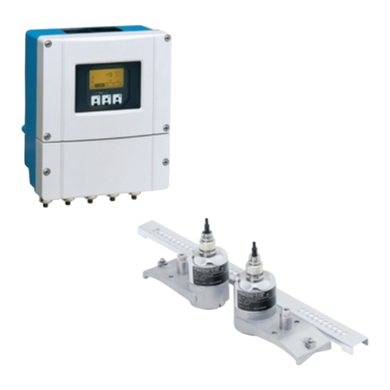
PROline Prosonic Flow 93 2 Identification Identification Device designation The “Prosonic Flow 93” flowmeter system consists of the following components: • Transmitter Prosonic Flow 93 • Prosonic Flow W and U and Prosonic Flow P sensors 2.1.1 Nameplate of the transmitter... -
Page 10: Nameplate Of The Sensors
2 Identification PROline Prosonic Flow 93 2.1.2 Nameplate of the sensors ENDRESS+HAUSER PROSONIC FLOW P XXXXX-XXXXXXXXXXXX Order Code: XA059D/ 12345678901 RY 2001 Ser.No.: 06/a3/..P-CL-1F-L-B Type: DN100-DN4000 -40°C (-40°F) ... +80°C (+175°F) OPEN CLOSE 0032 IP68 NEMA TYPE 6P APPROVED... -
Page 11: Nameplate Of The Prosonic Flow U
EMC requirements of EN 61326/A1. The measuring system described in these Operating Instructions is therefore in con- formity with the statutory requirements of the EC Directives. Endress+Hauser confirms succesful testing of the device by affixing to it the CE mark. - Page 12 2 Identification PROline Prosonic Flow 93 Endress+Hauser...
-
Page 13: Installation
PROline Prosonic Flow 93 3 Installation Installation Incoming acceptance, transport and storage 3.1.1 Incoming acceptance • Check the packaging and the contents for damage. • Check the shipment, make sure nothing is missing and that the scope of supply matches your order. -
Page 14: Installation Conditions
3 Installation PROline Prosonic Flow 93 Installation conditions 3.2.1 Installation dimensions The dimensions and the fitting lengths of the sensors and the transmitter are on Page 130 ff. 3.2.2 Installation location Correct measuring is possible only if the pipe is full. Avoid the following installation loca- tions: •... -
Page 15: Orientation
PROline Prosonic Flow 93 3 Installation 3.2.3 Orientation Vertical orientation Recommended orientation with upward direction of flow (View A). Entrained solids sink down. Gases rise away from the measuring sensor when fluid is not flowing. The piping can be completely drained and protected against build-up. -
Page 16: Inlet And Outlet Runs (Insertion Version)
3 Installation PROline Prosonic Flow 93 3.2.5 Inlet and outlet runs (Insertion version) If possible, install the sensor well clear of assemblies such as valves, T-pieces, elbows, etc. If several flow obstructions are installed, the longest inlet or outlet run must be con- sidered. -
Page 17: Sensor Arrangement (Clamp On)
PROline Prosonic Flow 93 3 Installation 3.2.7 Sensor arrangement (Clamp On) The transmitter offers a number of options between 1 and 4 traverses for the type of installation. Please note that the signal strength is reduced with each additional reflec- tion point in the pipe. -
Page 18: Two-Channel Measuring Devices
PROline Prosonic Flow 93 Two-channel measuring devices PROline Prosonic Flow 93 has two measuring channels which are independent of one another. In other words, the transmitter supports the simultaneous operation of two sen- sor pairs at two individual measuring channels. In doing so, the resources of the trans- mitter are split evenly between the two channels. -
Page 19: Two-Path Measurement
PROline Prosonic Flow 93 3 Installation Note! • The necessary settings for measured value output for two-channel measurement can be found under the appropriate ASSIGN function for the display, outputs and totalizers (see Description of Device Functions Prosonic Flow 93, BA071D/06/en/). - Page 20 3 Installation PROline Prosonic Flow 93 The following possibilities for outputting measured values are suitable for dual-path measurement: • Individual output of measured values from channel 1 and 2 • Arithmetic mean of the measured values from channel 1 and 2 (CH1 + CH2 / 2) The possibility of obtaining the mean value in dual-path measurement provides the advantage of a more stable measured value.
-
Page 21: Installation Instructions
PROline Prosonic Flow 93 3 Installation Installation instructions 3.4.1 Installing tensioning bands (Clamp On) For sensors W / P - DN 50...200 Push one of the supplied threaded bolts on the tensioning band (or both bolts in the case of sound velocity measurement). - Page 22 3 Installation PROline Prosonic Flow 93 Fig. 13: Tensioning band installation for DN 250...4000 For U sensors - DN 15...100 The procedure for installing the tensioning bands for the U sensor is explained on Page 28 in the “Installing the sensor Prosonic Flow U” Section.
-
Page 23: Use Of Weld Bolts For W/P Sensors
PROline Prosonic Flow 93 3 Installation 3.4.2 Use of weld bolts for W/P sensors Weld studs can be used instead of tensioning bands for the following types of installa- tion of the W / P Clamp On measuring sensors. Note! -
Page 24: Installing The Measuring Sensors Prosonic Flow P
3 Installation PROline Prosonic Flow 93 3.4.3 Installing the measuring sensors Prosonic Flow P 2 or 4 traverses version Fix a tensioning band for small or large nominal diameters as described on Page 21. Install the second tensioning band (threaded stud on the opposite side). -
Page 25: Installing The Measuring Sensors Prosonic Flow W/P (Clamp On)
PROline Prosonic Flow 93 3 Installation 3.4.4 Installing the measuring sensors Prosonic Flow W/P (Clamp On) 1 traverse version Fix a tensioning band for small or large nominal diameters as described on Page 21. Install the second tensioning band (threaded stud on the opposite side). - Page 26 3 Installation PROline Prosonic Flow 93 Fig. 17: Installing the sensor holders Coat the contact surface of the sensors with an even (approx. 1 mm thick) layer of coupling fluid (from the centre to the groove, see Page 98). Then carefully insert the sensors into the sensor holder. Press the sensor cover onto ▲...
-
Page 27: Installing The Measuring Sensors Prosonic Flow W (Clamp On)
PROline Prosonic Flow 93 3 Installation 3.4.5 Installing the measuring sensors Prosonic Flow W (Clamp On) 2 or 4 traverses version Fix a tensioning band for small or large nominal diameters as described on Page 21. Install the second tensioning band (threaded stud on the opposite side). -
Page 28: Installing The Measuring Sensors Prosonic Flow U (Clamp On)
3 Installation PROline Prosonic Flow 93 3.4.6 Installing the measuring sensors Prosonic Flow U (Clamp On) In the case of pipes in the DN 15…32 nominal diameter range, use the retaining vee (a) supplied to reinforce the pipe. This retaining vee is only included in the DN 15….40 installation set (see Accessories on Page 99). - Page 29 PROline Prosonic Flow 93 3 Installation Set the sensor distance on the sensor assembly by moving the sensors (c) along the assembly frame and tightening the sensor fixing nuts (d). Preferably, the sensor position is set symmetrically to the rail centre.
- Page 30 3 Installation PROline Prosonic Flow 93 Push down the screws (h) of tensioning band lock and tighten with a screwdriver so the bands cannot slip. If so desired, shorten the tensioning band then to the desired length. " Caution! – Danger of injury! Avoid sharp edges when shortening the tensioning band.
-
Page 31: Term Explanations For Prosonic Flow W (Insertion Version)
PROline Prosonic Flow 93 3 Installation 3.4.7 Term explanations for Prosonic Flow W (Insertion version) The graphic below provides you with an overview of the terms used when installing Prosonic Flow W (Insertion version). α Fig. 24: Term explanations 1 = Single path version... -
Page 32: Installing The Measuring Sensors Prosonic Flow W (Single Path Insertion Version)
3 Installation PROline Prosonic Flow 93 3.4.8 Installing the measuring sensors Prosonic Flow W (single path Insertion version) Determine the installation area (e) on the pipe section: – Installation location: Page 14 – Inlet/outlet run: Page 16 – Space required by the measuring point: approx. 1 x pipe diameter. - Page 33 PROline Prosonic Flow 93 3 Installation Draw the sensor distance (a) from the middle line starting from the first drillhole. Project the middle line to the back of the pipe and draw it on. Fig. 27: Installing the measuring sensors, steps 5 and 6 Mark the drillhole on the middle line on the back of the pipe.
-
Page 34: Endress+Hauser
3 Installation PROline Prosonic Flow 93 10. Weld in both sensor holders. After welding, check the distance between the drill holes once again and measure the path length. Note! To determine the path length use: – the “Sensor Installation” Quick Setup menu if the measuring device has a local operation. -
Page 35: Installing The Measuring Sensors Prosonic Flow W (Dual Path Insertion Version)
PROline Prosonic Flow 93 3 Installation 3.4.9 Installing the measuring sensors Prosonic Flow W (dual path Insertion version) Set installation range (e) on pipe section: – Installation location see Page 14 – Inlet/outlet run see Page 16 – Space required by the measuring point approx. 1x pipe diameter. - Page 36 3 Installation PROline Prosonic Flow 93 You can correct the middle line with the arc length. Fig. 33: Installing the dual path measuring sensors, steps 5 and 6 Project the corrected middle line onto the other side of the pipe and draw this on (half pipe circumference).
- Page 37 PROline Prosonic Flow 93 3 Installation 11. Insert the sensor holders into the first two drillholes. To adjust the weld-in depth, both sensor holders can be fixed with the special tool for insertion depth regulation (optional) and then aligned using the tie rod. The sensor holder must be flush with the inner side of the pipe.
- Page 38 3 Installation PROline Prosonic Flow 93 14. Then screw the sound velocity sensors into the sensor holders by hand. If you use a tool, the maximum torque permissible is 30 Nm. 15. Insert the sensor cable plug into the intended opening and manually tighten the plug to the stop.
-
Page 39: Installing The Sound Velocity Measuring
PROline Prosonic Flow 93 3 Installation 3.4.10 Installing the sound velocity measuring sensors DDU 18 (accessories) Fix a tensioning band for small or large nominal diameters as described on Page 21. The two threaded bolts must be positioned opposite each other on either side of the pipe. -
Page 40: Installing The Wall Thickness Measuring
3 Installation PROline Prosonic Flow 93 3.4.11 Installing the wall thickness measuring sensors DDU 19 (accessories) Variant 1 Fix a tensioning band for small or large nominal diameters as described on Page 21. Coat the contact surface of the sensor with an even (approx. 1 mm thick) layer of coupling fluid (starting from the groove, through the centre and to the opposite side). -
Page 41: Installing The Wall-Mount Housing
PROline Prosonic Flow 93 3 Installation 3.4.12 Installing the wall-mount housing There are various ways of installing the wall-mount transmitter housing: • Direct wall mounting • Panel mounting (with separate mounting kit, accessories → Page 99) • Pipe mounting (with separate mounting kit, accessories → Page 99) "... - Page 42 3 Installation PROline Prosonic Flow 93 Panel mounting Prepare the installation opening in the panel (Fig. 43). Slide the housing through the front of the panel cutout. Screw the fasteners to the wall-mount housing. Screw the threaded rods into the brackets and tighten until the housing is firmly fixed to the panel wall.
-
Page 43: Installation Check
PROline Prosonic Flow 93 3 Installation Installation check Perform the following checks after installing the measuring device on the pipe: Device condition and specifications Notes − Is the device damaged (visual inspection)? Does the device correspond to specifications at the measuring point, see Page 121 ff. - Page 44 3 Installation PROline Prosonic Flow 93 Endress+Hauser...
-
Page 45: Wiring
PROline Prosonic Flow 93 4 Wiring Wiring Warning! When connecting Ex-certified devices, see the notes and diagrams in the Ex-specific supplement to these Operating Instructions. Please do not hesitate to contact your E+H sales office if you have any questions. -
Page 46: Cable Specifications
4 Wiring PROline Prosonic Flow 93 Legend: View A Detail B Connection compartment cover Sensor cable plug, channel 1, upstream Sensor cable plug, channel 1, downstream Cable entry channel 2 (not required) Cable entry channel 2 (not required) Cable gland cover... -
Page 47: Connecting The Measuring Unit
PROline Prosonic Flow 93 4 Wiring Connecting the measuring unit 4.2.1 Connecting the transmitter Warning! • Risk of electric shock. Switch off the power supply before opening the device. Do not install or wire the device while it is connected to the power supply. Failure to comply with this precaution can result in irreparable damage to the electronics. -
Page 48: Terminal Assignment
4 Wiring PROline Prosonic Flow 93 4.2.2 Terminal assignment Terminal No. (inputs/outputs) Order variant 20 (+) / 21 (–) 22 (+) / 23 (–) 24 (+) / 25 (–) 26 (+) / 27 (–) Fixed communication boards (fixed assignment) Current output −... -
Page 49: Hart Connection
PROline Prosonic Flow 93 4 Wiring 4.2.3 HART connection Users have the following connection options at their disposal: • Direct connection to transmitter by means of terminals 26 / 27 • Connection by means of the 4...20 mA circuit. Note! •... -
Page 50: Potential Equalisation
4 Wiring PROline Prosonic Flow 93 Potential equalisation For potential equalisation no special measures are necessary. Note! For instruments for use in hazardous areas, observe the corresponding guidelines in the specific Ex documentation. Degree of protection Transmitter (wallmount housing) The transmitter fulfills all the requirements for IP 67 degree of protection. Compliance... - Page 51 PROline Prosonic Flow 93 4 Wiring Flowrate measuring sensors P and W (Clamp on / Insertion) The flowrate measuring sensors P and W as well as the sound velocity measuring sen- sors DDU 18 fulfill all the requirements for IP 67 or 68 degree of protection (please observe the informations on the nameplate of the sensor).
-
Page 52: Connection Check
4 Wiring PROline Prosonic Flow 93 Connection check Perform the following checks after completing electrical installation of the measuring device: Device condition and specifications Notes − Are cables or the device damaged (visual inspection)? Electrical connection Notes Does the supply voltage match the specifications on the nameplate? 85...260 V AC (45...65 Hz) -
Page 53: Operation
PROline Prosonic Flow 93 5 Operation Operation Quick operation guide You have a number of options for configuring and commissioning the device: 1. Local operation (optional) → Page 54 The local operation enables you to read all of the important parameters directly at the measuring point, configure device-specific parameters in the field and commission the instrument. -
Page 54: Operation Via The Local Display
5 Operation PROline Prosonic Flow 93 Operation via the local display 5.2.1 Display and operating elements The local operation enables you to read all important parameters directly at the meas- uring point and configure the device using the “Quick Setup” or the function matrix. - Page 55 PROline Prosonic Flow 93 5 Operation Display (operation mode) The display area consists of three lines in all; this is where measured values are dis- played, and/or status variables (direction of flow, bar graph, etc.). You can change the assignment of display lines to different variables to suit your needs and preferences (→...
- Page 56 5 Operation PROline Prosonic Flow 93 Icons The icons which appear in the field on the left make it easier to read and recognize measured variables, device status, and error messages. Icon Meaning Icon Meaning System error Process error Fault message...
-
Page 57: Brief Operating Instructions For The Function Matrix
PROline Prosonic Flow 93 5 Operation Brief operating instructions for the function matrix Note! • See the general notes on Page 58. • Function descriptions → see the “Description of Device Functions” manual HOME position → F → Enter function matrix Select a block (e.g. -
Page 58: General Notes
There is no need to change these parameters under normal circumstances and conse- quently, they are protected by a special code known only to the E+H service organisa- tion. Please contact Endress+Hauser if you have any questions. Endress+Hauser... -
Page 59: Disabling The Programming Mode
PROline Prosonic Flow 93 5 Operation 5.3.3 Disabling the programming mode Programming mode is disabled if you do not press an operating element within 60 sec- onds after you return to the HOME position. You can also disable programming in the “ACCESS CODE” function by entering any number (other than the customer's code). -
Page 60: Communication (Hart)
5 Operation PROline Prosonic Flow 93 Note! • Error status can be output via the relay outputs. • If there is an error message present a higher or lower signal on alarm level can be output via the current output in accordance with NAMUR Recommendation NE 43. -
Page 61: Operating Options
PROline Prosonic Flow 93 5 Operation 5.5.1 Operating options For the complete operation of the measuring device, including device-specific com- mands, there are Device Description (DD) files available to the user to provide the following operating aids and programs: HART communicator DXR 375 Selecting device functions with a HART communicator is a process involving a number of menu levels and a special HART function matrix. -
Page 62: Device Variables And Process Variables
5 Operation PROline Prosonic Flow 93 5.5.2 Device variables and process variables Device variables: The following device variables are available using the HART protocol: ID (decimal) Device variable OFF (not assigned) Volume flow channel 1 Volume flow channel 2 Volume flow mean value... -
Page 63: Universal / Common Practice Hart Commands
PROline Prosonic Flow 93 5 Operation 5.5.3 Universal / common practice HART commands The following table contains all the universal and common practice commands sup- ported by Prosonic Flow 93. Command No. Command data Response data HART command / Access type... - Page 64 5 Operation PROline Prosonic Flow 93 Command No. Command data Response data HART command / Access type (numeric data in decimal form) (numeric data in decimal form) Read the primary process none 24 bytes are sent as a response: variable as current in mA and –...
- Page 65 PROline Prosonic Flow 93 5 Operation Command No. Command data Response data HART command / Access type (numeric data in decimal form) (numeric data in decimal form) Read user message none Bytes 0-24: User message Access type = read Note! You can write the user message using Com- mand 17.
- Page 66 5 Operation PROline Prosonic Flow 93 Command No. Command data Response data HART command / Access type (numeric data in decimal form) (numeric data in decimal form) Write TAG, TAG descriptor With this parameter, you can store an 8 charac-...
- Page 67 PROline Prosonic Flow 93 5 Operation Command No. Command data Response data HART command / Access type (numeric data in decimal form) (numeric data in decimal form) Write unit of primary process Set unit of primary process variable Only unit...
- Page 68 5 Operation PROline Prosonic Flow 93 Command No. Command data Response data HART command / Access type (numeric data in decimal form) (numeric data in decimal form) Write assignments of the Setting of the device variables to the four proc-...
-
Page 69: Device Status / Error Messages
PROline Prosonic Flow 93 5 Operation 5.5.4 Device status / Error messages You can read the extended device status, in this case, current error messages, via Com- mand “48”. The command delivers information which are partly coded in bits (see table below). - Page 70 5 Operation PROline Prosonic Flow 93 → Byte Error no. Short error description ( Page 104 ff.) not assigned – not assigned – not assigned – not assigned – No data reception between amplifier and I/O board not assigned –...
- Page 71 PROline Prosonic Flow 93 5 Operation → Byte Error no. Short error description ( Page 104 ff.) not assigned – not assigned – not assigned – not assigned – not assigned – not assigned – not assigned – not assigned –...
- Page 72 5 Operation PROline Prosonic Flow 93 → Byte Error no. Short error description ( Page 104 ff.) not assigned – Channel 1: Initialization running. All outputs set to “0”. Channel 2: Initialization running. All outputs set to “0”. not assigned –...
- Page 73 PROline Prosonic Flow 93 5 Operation → Byte Error no. Short error description ( Page 104 ff.) not assigned – not assigned – not assigned – not assigned – not assigned – not assigned – not assigned – not assigned –...
-
Page 74: Switching Hart Write Protection
5 Operation PROline Prosonic Flow 93 5.5.5 Switching HART write protection on and off A jumper on the I/O board provides the means of activating or deactivating HART write protection. Warning! Risk of electric shock. Exposed components carry dangerous voltages. Make sure that the power supply is switched off before you remove the cover of the electronics com- partment. -
Page 75: Commissioning
PROline Prosonic Flow 93 6 Commissioning Commissioning Function check Make sure that all final checks have been completed before you start up your measuring point: • “Installation check” checklist → Page 43 • “Connection check” checklist → Page 51 Switching on the measuring device Once the connection checks (see Page 51) have been successfully completed, it is time to switch on the power supply. -
Page 76: Commissioning Via Local Display
6 Commissioning PROline Prosonic Flow 93 Commissioning via local display 6.2.1 “Sensor” Quick Setup menu If the measuring device is equipped with a local operation, the sensor distance can be ascertained using the “Sensor” Quick Setup menu (Fig. 58). If a measuring device does not have a local operation, the individual parameters and functions must be configured via the configuration program FieldTool (see Page 84). - Page 77 PROline Prosonic Flow 93 6 Commissioning Note! • The display returns to the cell SETUP SENSOR (1001) if you press the ESC key com- bination (X) during interrogation. • If you confirm the inquiry “Automatic configuration of the display?” as YES, the config- uration of the display will be carried out as follows: main line = volume flow, additional line = totalizer 1, information line = operational/system condition.
-
Page 78: Commissioning" Quick Setup Menu
6 Commissioning PROline Prosonic Flow 93 6.2.2 “Commissioning” Quick Setup menu If the measuring device is equipped with a local operation, all the device parameters important for standard measuring mode can be configured easily and quickly using the “Commissioning” Quick Setup menu (Fig. 59). - Page 79 PROline Prosonic Flow 93 6 Commissioning Note! • The display returns to the cell QUICK SETUP COMMISSIONING (1002) if you press the ESC key combination (X) during interrogation. • If you confirm the inquiry “Automatic configuration of the display?” as YES, the config- uration of the display will be carried out as follows: main line = volume flow, additional line = totalizer 1, information line = operational/system condition.
-
Page 80: Pulsating Flow" Quick Setup Menu
6 Commissioning PROline Prosonic Flow 93 6.2.3 “Pulsating Flow” Quick Setup menu Certain types of pump such as reciprocating, peristaltic and cam-type pumps, for example, create a flow characterized by severe periodic fluctuations (Fig. 60). Negative flows can occur with pumps of these types on account of the closing volume of the valves or valve leaks. - Page 81 PROline Prosonic Flow 93 6 Commissioning Using the “Pulsating Flow” Quick Setup menu If the measuring device is equipped with a local operation, all the device parameters important for standard measuring mode can be configured easily and quickly using the “Pulsating Flow”...
- Page 82 6 Commissioning PROline Prosonic Flow 93 Note! • The display returns to the cell QUICK SETUP PULSATING FLOW (1003) if you press the ESC key combination (X) during interrogation. • You can call this Quick Setup menu either directly from the “COMMISSIONING” Quick Setup menu or manually by means of the QUICK SETUP PULSATING FLOW function (1003).
- Page 83 PROline Prosonic Flow 93 6 Commissioning “Pulsating Flow” Quick Setup menu → → HOME position MEASURED VARIABLE (A) → → MEASURED VARIABLE QUICK SETUP (B) → N → QUICK SETUP QS PULSE. FLOW (1003) Function No. Function name Setting to select (P)
-
Page 84: Commissioning Via A Configuration Program
6 Commissioning PROline Prosonic Flow 93 Commissioning via a configuration program 6.3.1 Sensor installation For sensor installation with the configuration program FieldTool any “Quick Setup” menus which correspond to the local operation exist. Other methods (see table) are available for determining the relevant values for sensor distance, wire length, etc. - Page 85 PROline Prosonic Flow 93 6 Commissioning Procedure (determining data for sensor installation) You can use the following tables to select and configure, in the correct order, the func- tions required to install the sensor: • “Clamp On” sensor installation → Page 85 •...
-
Page 86: Wire Length
6 Commissioning PROline Prosonic Flow 93 → → BASIC FUNCTION BASIC FUNCTION → → ▼ PROCESS PARAM. CH1/CH2 PROCESS PARAM. CH1/CH2 → → LIQUID DATA LIQUID DATA Liquid in the pipe LIQUID (6540) LIQUID Liquid temperature TEMPERATURE (6541) TEMPERATURE Liquid sound velocity... -
Page 87: Arc Length
PROline Prosonic Flow 93 6 Commissioning “Insertion” sensor installation Procedure Local operation (Quick Setup) FieldTool ▼ ▼ Selection - Input - display → → BASIC FUNCTION BASIC FUNCTION → → ▼ SENSOR DATA CH1/CH2 SENSOR DATA CH1/CH2 → → SENSOR PARAM. - Page 88 6 Commissioning PROline Prosonic Flow 93 “Liquid sound velocity” measurement (only for Clamp On) Procedure Local operation (Quick Setup) FieldTool ▼ ▼ Selection - Input - display → → BASIC FUNCTION BASIC FUNCTION → → ▼ SENSOR DATA CH1/CH2 SENSOR DATA CH1/CH2 →...
- Page 89 PROline Prosonic Flow 93 6 Commissioning “Pipe sound velocity” measurement (only for Clamp On) Procedure Local operation (Quick Setup) FieldTool ▼ ▼ Selection - Input - display → → BASIC FUNCTION BASIC FUNCTION → → ▼ SENSOR DATA CH1/CH2 SENSOR DATA CH1/CH2 →...
-
Page 90: Commissioning
6 Commissioning PROline Prosonic Flow 93 “Wall thickness” measurement (only for Clamp On) Procedure Local operation (Quick Setup) FieldTool ▼ ▼ Selection - Input - display → → BASIC FUNCTION BASIC FUNCTION → → ▼ SENSOR DATA CH1/CH2 SENSOR DATA CH1/CH2 →... -
Page 91: Application Specific Commissioning
PROline Prosonic Flow 93 6 Commissioning Application specific commissioning 6.4.1 Zero point adjustment Consequently, zero point adjustment is generally not necessary. Experience shows that the zero point adjustment is advisable only in special cases: • To achieve highest measuring accuracy also with very small flow rates. - Page 92 6 Commissioning PROline Prosonic Flow 93 Performing a zero point adjustment Operate the system until normal operating conditions resume. Stop the flow (v = 0 m/s). Check the shut-off valves for leaks. Check that operating pressure is correct. Using the local operation, select the “ZERO POINT ADJUSTMENT” function in the function matrix: HOME →...
-
Page 93: Advanced Diagnostic Functions
PROline Prosonic Flow 93 6 Commissioning 6.4.2 Advanced diagnostic functions Changes to the measuring system can be detected at an early stage by means of the optional software package “Advanced Diagnostics” (F-Chip, accessories → Page 99). Normally, these influences reduce the measuring accuracy of the system or may lead to serious system errors. - Page 94 6 Commissioning PROline Prosonic Flow 93 Triggering warning messages If required, a limit value can be assigned to all the process/device parameters relevant to the diagnostic functions. A warning message is triggered if this limit value is exceeded → function “WARNING MODE (7403)”.
-
Page 95: Hardware Configuration
PROline Prosonic Flow 93 6 Commissioning Hardware configuration 6.5.1 Current output: active/passive The current output can be configured as “active” or “passive” by means of various jump- ers on the I/O board or the current submodule. Warning! Risk of electric shock. Exposed components carry dangerous voltages. Make sure that the power supply is switched off before you remove the cover of the electronics com- partment. -
Page 96: Relay Contacts: Normaly Open/Normaly Closed
6 Commissioning PROline Prosonic Flow 93 6.5.2 Relay contacts: Normaly open/normaly closed The relay contact can be configured as normally open (NO or make) or normally closed (NC or break) contacts by means of two jumpers on the I/O board or the relay submod- ule. -
Page 97: Data Storage Device (Dat, F-Chip)
PROline Prosonic Flow 93 6 Commissioning Data storage device (DAT, F-Chip) T-DAT (Transmitter-DAT) The T-DAT is an exchangeable data storage device in which all transmitter parameters and settings are stored. The operator has to transfer specific parameterisation values from EEPROM to T-DAT and vice versa ( = manual safety function). -
Page 98: Maintenance
7 Maintenance PROline Prosonic Flow 93 Maintenance The Prosonic Flow 93 flow measuring system requires no special maintenance. Exterior cleaning When cleaning the exterior of measuring devices, always use cleaning agents that do not attack the surface of the housing and the seals. -
Page 99: Accessories
PROline Prosonic Flow 93 8 Accessories Accessories Various accessories, which can be ordered separately from Endress+Hauser, are avail- able for the transmitter and the sensor. The E+H service organisation can provide detailed information on the order codes of your choice. - Page 100 8 Accessories PROline Prosonic Flow 93 Accessory Description Order Code − Installation set Clamp On Without sensor fastening DK9IC − sensor fastening for Tensioning bands DN 50...200 DK9IC − Prosonic Flow W/P Tensioning bands DN 200...600 DK9IC − Tensioning bands DN 600...2000 DK9IC −...
- Page 101 PROline Prosonic Flow 93 8 Accessories Accessory Description Order Code − Applicator Software for selecting and configuring flow DKA80 meters. Applicator can be downloaded from the Internet or ordered on CD-ROM for installation on a local Contact your E+H representative for more infor- mation.
- Page 102 8 Accessories PROline Prosonic Flow 93 Endress+Hauser...
-
Page 103: Trouble-Shooting
PROline Prosonic Flow 93 9 Trouble-shooting Trouble-shooting Trouble-shooting instructions Always start trouble-shooting with the checklist below, if faults occur after start-up or during operation. This takes you directly (via various queries) to the cause of the prob- lem and the appropriate remedial measures. -
Page 104: System Error Messages
In the event of a serious fault, a flowmeter might have to be returned to the manufacturer for repair. The procedures on Page 8 must be carried out before you return a flowmeter to Endress+Hauser. Always enclose a fully completed “Declaration of contamination” form. You will find a preprinted form at the back of this manual. - Page 105 PROline Prosonic Flow 93 9 Trouble-shooting Type Error message / No. Cause Remedy / spare part TRANSM. SW-DAT Transmitter: 1. Check whether the T-DAT is # 042 Error accessing the calibration correctly plugged into the → values stored in the T-DAT.
- Page 106 9 Trouble-shooting PROline Prosonic Flow 93 Type Error message / No. Cause Remedy / spare part A / C COMPATIB. Due to different software ver- Module with lower software ver- # 121 sions, I/O board and amplifier sion has either to be actualizied by...
- Page 107 PROline Prosonic Flow 93 9 Trouble-shooting Type Error message / No. Cause Remedy / spare part STACK PULSE n The temporarily buffered flow por- 1. Increase the setting for pulse # 347…350 tions (measuring mode for pulsat- weighting ing flow) could not be cleared or 2.
- Page 108 9 Trouble-shooting PROline Prosonic Flow 93 Type Error message / No. Cause Remedy / spare part SIGNAL LOW CH1 Attenuation of acoustic measure- – Check to see if the coupling # 392 ment section too high. fluid must be renewed.
- Page 109 PROline Prosonic Flow 93 9 Trouble-shooting Type Error message / No. Cause Remedy / spare part SIM.FEHLER.K1 Simulation of response to error of Switch off simulation # 696 channel 1/2 (outputs) active SIM.FEHLER.K2 # 697 DEV. TEST ACT. The measuring device is being –...
-
Page 110: Process Error Messages
9 Trouble-shooting PROline Prosonic Flow 93 Process error messages Process errors can be defined as either “Fault” or “Notice” messages and can thereby be weighted differently. Determination of this is done via the function matrix (→ see the “Description of Device Functions” manual). -
Page 111: Process Errors Without Messages
Returning devices to E+H The procedures on Page 8 must be carried out before you return a flowm- eter requiring repair or calibration to Endress+Hauser. In all cases, enclose a duly completed “Declaration of contamination” form with the flowmeter. You will find a preprinted form at the end of these Operating Instructions. -
Page 112: Response Of Outputs To Errors
9 Trouble-shooting PROline Prosonic Flow 93 Response of outputs to errors Note! The failsafe mode of totalizers, current, pulse and frequency outputs can be customized by means of various functions in the function matrix. You will find detailed information on these procedures in the “Description of Device Functions”... - Page 113 PROline Prosonic Flow 93 9 Trouble-shooting Failsafe mode of outputs and totalizers Process/system error is present Positive zero return is activated Frequency output FALLBACK VALUE Output signal corresponds to → Signal output 0 Hz “zero flow” FAILSAFE LEVEL Output of the frequency specified in the FAIL- SAFE VALUE function (No.
-
Page 114: Spare Parts
9 Trouble-shooting PROline Prosonic Flow 93 Spare parts Chap. 9.1 contains a detailed trouble-shooting guide. The measuring device, more over, provides additional support in the form of continuous self-diagnosis and error mes- sages.Trouble-shooting can entail replacing defective components with tested spare parts. -
Page 115: Removing And Installing Printed Circuit Boards
“INPUT / OUTPUT 2" slot = terminals 24 / 25 “INPUT / OUTPUT 3" slot = terminals 22 / 23 “INPUT / OUTPUT 4" slot = terminals 20 / 21 Installation is the reverse of the removal procedure. " Caution! Use only original Endress+Hauser replacement parts. Endress+Hauser... - Page 116 9 Trouble-shooting PROline Prosonic Flow 93 T / O T / O T / O Fig. 68: Wall-mount housing: removing and installing printed circuits boards Housing cover Electronics module Ribbon cable (display module) Screws of electronics compartment cover Aperture for installing/removing boards...
-
Page 117: Installation/Removal Of Flowmeter Sensors W "Insertion
PROline Prosonic Flow 93 9 Trouble-shooting Installation/removal of flowmeter sensors W “Insertion” The active part of the flowmeter sensor W “Insertion” can be replaced without interrupt- ing the process. Pull the sensor connector (1) out of the sensor cover (3). -
Page 118: Replacing The Device Fuse
– Power supply 85...260 V AC → 0.8 A slow-blow / 250 V; 5.2 x 20 mm – Ex-system → see appropriate Ex documentation Assembly is the reverse of the disassembly procedure. " Caution! Use only original Endress+Hauser replacement parts. Fig. 70: Replacing the device fuse on the power unit board Protective cap Device fuse Endress+Hauser... -
Page 119: Software History
PROline Prosonic Flow 93 9 Trouble-shooting 9.10 Software history Software version / Changes to software Documentation date Changes/Additions Amplifier − V 1.00.00 / 06.2001 Original software. Compatible with: – FieldTool – HART communicator DXR 275 (OS 4.6 and higher) with rev. 1, DD 1. - Page 120 9 Trouble-shooting PROline Prosonic Flow 93 Endress+Hauser...
-
Page 121: Technical Data
PROline Prosonic Flow 93 10 Technical data Technical data 10.1 Technical data at a glance 10.1.1 Application • Measuring the flow rate of fluids in closed piping systems. • Applications in measuring, control and regulation technology for monitoring processes. 10.1.2... -
Page 122: Output
10 Technical data PROline Prosonic Flow 93 10.1.4 Output Output signal Current output: Active/passive selectable, galvanically isolated, time constant selectable (0.05...100 s), full scale value selectable, temperature coefficient: typically 0.005% o.r./°C; resolution: 0.5 µmA • active: 0/4...20 mA, R <700 Ω (for HART: R ≥... -
Page 123: Power Supply
PROline Prosonic Flow 93 10 Technical data 10.1.5 Power supply Electrical connections see Page 45 ff. Potential equalisation see Page 50 ff. Cable entries Power supply and signal cables (inputs/outputs): • Cable entry M20 x 1.5 or • Cable gland for cables with Ø 6...12 mm •... -
Page 124: Performance Characteristics
10 Technical data PROline Prosonic Flow 93 10.1.6 Performance characteristics • Fluid temperature: +28 °C ± 2 K Reference operating • Ambient temperature: +22 °C ± 2 K conditions • Warm-up period: 30 minutes Installation: • Inlet run >10 x DN •... -
Page 125: Operating Conditions
PROline Prosonic Flow 93 10 Technical data 10.1.7 Operating conditions Installation Installation instructions Any orientation (vertical, horizontal) Restrictions and additional installation instructions → Page 14 ff. Inlet and outlet runs Clamp On version: see Page 15 Insertion version: see Page 16... - Page 126 10 Technical data PROline Prosonic Flow 93 • Transmitter Prosonic Flow 93: Degree of passembly framerotection IP 67 (NEMA 4X) • Flowrate measuring sensors Prosonic Flow P (Clamp On): IP 68 (NEMA 6P) • Flowrate measuring sensors Prosonic Flow W (Clamp On) IP 67 (NEMA 4X) •...
-
Page 127: Mechanical Construction
PROline Prosonic Flow 93 10 Technical data 10.1.8 Mechanical construction Design / dimensions see Page 130 ff. Weight Transmitter housing: • Wall-mount housing: 6.0 kg Measuring sensors: • Flowrate measuring sensors P incl. mounting rail and tensioning band: 2.8 kg •... -
Page 128: Human Interface
CE mark The measuring system is in conformity with the statutory requirements of the EC Directives. Endress+Hauser confirms successful testing of the device by affixing to it the CE mark. Other standards and EN 60529: guidelines... -
Page 129: 10.1.11 Ordering Information
10.1.12 Accessories Various accessories, which can be ordered separately from Endress+Hauser, are avail- able for the transmitter and the sensor (see Page 99). The E+H service organisation can provide detailed information on the order codes of your choice. -
Page 130: Dimensions Of Wall-Mount Housing
10 Technical data PROline Prosonic Flow 93 10.2 Dimensions of wall-mount housing > 50 11.5 11.5 → Fig. 72: Dimensions of wall-mount housing (panel mounting and pipe installation Page 42) Endress+Hauser... -
Page 131: Dimensions Of P Sensors
PROline Prosonic Flow 93 10 Technical data 10.3 Dimensions of P sensors 2 or 4 traverses version Fig. 73: Dimensions of P sensor (version: 2 or 4 traverses) a = Sensor spacing can be determined using Quick Setup b = Pipe outer diameter (defined by the application) 1 traverse version Fig. -
Page 132: Dimensions Of W Sensors (Clamp On)
10 Technical data PROline Prosonic Flow 93 10.4 Dimensions of W sensors (Clamp On) Fig. 75: Dimensions of W sensor (Clamp On) a = Sensor spacing can be determined using Quick Setup b = Pipe outer diameter (defined by the application) 10.5... -
Page 133: Dimensions Of W Sensors (Insertion Version)
PROline Prosonic Flow 93 10 Technical data 10.6 Dimensions of W sensors (Insertion version) Single path version ~ 150 Fig. 77: Dimensions of W sensor (Insertion version, single path) A = View A a = Pipe outer diameter (defined by the application) - Page 134 10 Technical data PROline Prosonic Flow 93 Dual path version α Fig. 78: Dimensions of W sensor (Insertion version, dual path) B = View B a = Pipe outer diameter (defined by the application) b = Sensor spacing determinable using Quick Setup c = Path length determinable using Quick Setup Π...
- Page 135 PROline Prosonic Flow 93 Index Index Dimensions P sensors ......131 Accessories .
- Page 136 Index PROline Prosonic Flow 93 HART Local display Device status / Error messages ... . . 69 see Display Device variables and process variables ..62 Low flow cutoff .
- Page 137 PROline Prosonic Flow 93 Index Process error messages ....110 Temperature ranges Process errors without messages ... . . 111 Ambient temperature .
- Page 138 Index PROline Prosonic Flow 93 Endress+Hauser...
- Page 139 'HFODUDWLRQ RI FRQWDPLQDWLRQ Dear customer, Because of legal determinations and for the safety of our employees and operating equipment we need this “Declaration of contamination” with your signature before your order can be handled. Please put the completely filled in declaration to the instrument and to the shipping documents in any case. Add also safety sheets and/or specific handling instructions if necessary.
- Page 140 Poland – Wroclaw Costa Rica – San Jose ❑ Sakura Endress Co. Ltd. ❑ Endress+Hauser Polska Sp. z o.o. Tel. (01) 88 05 60, Fax (01) 88 05 63 35 Euro-Tec S.A. Tel. (0422) 54 06 11, Fax (0422) 55 02 75 Tel.