Table of Contents
Advertisement
Quick Links
FORM NO.:6U6K-B01E-NB-EN
AIR-COOLED CHILLER
AND HEAT PUMP
INSTALLATION,COMMISSIONING,
Supersedes: 6U6K-B01E-NA-EN
FORM NO.: 6U6K-B01E-NB-EN
OPERATION & MAINTENANCE
YMAA / YMPA 0045-0260
AIR-COOLED CHILLER AND HEAT PUMP
50Hz
44-255kW
R410A
Issue Date:
February 26, 2018
JOHNSON CONTROLS
1
Cooke Industries - Phone: +64 9 579 2185
Email: sales@cookeindustries.co.nz
Web: www.cookeindustries.co.nz
Advertisement
Table of Contents
Troubleshooting

Related Manuals for York YMAA 0045


Summary of Contents for York YMAA 0045
- Page 1 FORM NO.:6U6K-B01E-NB-EN AIR-COOLED CHILLER AND HEAT PUMP INSTALLATION,COMMISSIONING, Supersedes: 6U6K-B01E-NA-EN FORM NO.: 6U6K-B01E-NB-EN OPERATION & MAINTENANCE YMAA / YMPA 0045-0260 AIR-COOLED CHILLER AND HEAT PUMP 50Hz 44-255kW R410A Issue Date: February 26, 2018 JOHNSON CONTROLS Cooke Industries - Phone: +64 9 579 2185 Email: sales@cookeindustries.co.nz Web: www.cookeindustries.co.nz...
- Page 2 FORM NO.:6U6K-B01E-NB-EN IMPORTANT! READ BEFORE PROCEEDING! GENERAL SAFETY GUIDELINES property in which it is situated, as well as severe personal This equipment is a relatively complicated apparatus. as well as severe personal injury or death to themselves This equipment is a relatively complicated apparatus. injury or death to themselves and people at the site.
- Page 3 FORM NO.: 6U6K-B01E-NB-EN CHANGEABILITY OF THIS DOCUMENT In complying with Johnson Controls’ policy for continuous regarding the applicability of these documents, rigging, product improvement, the information contained in this lifting, and operating/service personnel should verify whether document is subject to change without notice. Johnson Controls the equipment has been modified and if current literature is makes no commitment to update or provide current information available from the owner of the equipment prior to performing...
- Page 4 Voltage 50: 400V/3Ph/50Hz Refrigerant E: R410A Unit Designator P: Premium Efficiency Nominal Capacity (Unit: kW) Design Series Chiller Type P: Heat Pump A: Chiller Modular YORK JOHNSON CONTROLS Cooke Industries - Phone: +64 9 579 2185 Email: sales@cookeindustries.co.nz Web: www.cookeindustries.co.nz...
-
Page 5: Table Of Contents
FORM NO.: 6U6K-B01E-NB-EN Table of Contents SECTION 1 – GENERAL INFORMATION AND SAFETY INTRODUCTION WARRANTY SAFETY ABOUT THIS MANUAL MISUSE OF EQUIPMENT SECTION 2 – PRODUCT DESCRIPTION INTRODUCTION GENERAL SYSTEM DESCRIPTION OPTIVIEW LT CONTROLLER POWER PANEL DRIVER PANEL STANDARD EQUIPMENT OPTIONS HYDRO KIT REFRIGERANT FLOW DIAGRAM... - Page 6 FORM NO.:6U6K-B01E-NB-EN SECTION 5 – TECHNICAL DATA OPERATIONAL LIMITATIONS PHYSICAL DATA ELECTRICAL DATA ELECTRICAL DIAGRAM WIRING DIAGRAM DIP SWITCH SETTING DIMENSIONS TECHNICAL DATA – CLEARANCES ISOLATORS – WEIGHT DISTRIBUTION AND ISOLATOR MOUNTING POSITIONS ISOLATOR DETAILS – ONE INCH DEFLECTION SPRING ISOLATOR CROSS-REFERENCE ONE INCH DEFLECTION –...
- Page 7 FORM NO.: 6U6K-B01E-NB-EN SECTION 9 – UNIT OPERATION CAPACITY CONTROL SUCTION PRESSURE LIMIT CONTROLS DISCHARGE PRESSURE LIMIT CONTROLS COMPRESS RATIO LIMIT CONTROLS DISCHARGE TEMPERATURE CONTROLS INVERTER FREQUENCY CONTROL LIQUID TEMP. CONTROL VARIABLE LEAVING WATER TEMPERATURE CONTROLS COMPRESSOR SEQUENCING DEFROST CONTROLS ANTI-RECYCLE TIMER ANTI-COINCIDENCE TIMER EVAPORATOR AND PIPING HEATER CONTROLS...
-
Page 8: Section 1 - General Information And Safety
Authorized Johnson Controls Service Center (see SECTION 6 – COMMISSIONING). specified in this manual. • Only genuine YORK approved spare parts, oils, coolants, and This manual contains all the information required for correct refrigerants must be used. •... -
Page 9: About This Manual
SECTION 1 – GENERAL INFORMATION AND SAFETY FORM NO.: 6U6K-B01E-NB-EN construction of units and provide CE Listing Label. The unit must not be operated outside the design parameters specified in this manual. Fluorinated Greenhouse Gases • Structural Support This equipment contains fluorinated greenhouse gases covered by the Kyoto Protocol. - Page 10 FORM NO.:6U6K-B01E-NB-EN SECTION 1 – GENERAL INFORMATION AND SAFETY Heat Radiation High Temperature and Pressure Cleaning Some of the visible parts like discharge pipe and driver heat High temperature and pressure cleaning methods (e.g. steam sink may work under high temperatures, thus radiate high heat cleaning) should not be used on any part of the pressure system flux.
-
Page 11: Section 2 - Product Description
SECTION 2 – PRODUCT DESCRIPTION Compressor INTRODUCTION YORK Air-Cooled Modular Chiller and Heat Pump provide Each unit has a DC (direct current) inverter scroll compressor chilled water or (and) hot water for all air conditioning which is driven directly by an external driver, located next to applications using central station air handling or terminal the control panel. -
Page 12: Optiview Lt Controller
FORM NO.:6U6K-B01E-NB-EN SECTION 2 – PRODUCT DESCRIPTION pressure of the coil is 45 bar (650 PSIG). excellent heat transfer performance with a compact size and low weight, reducing structural steel requirements on the job Fans – The condenser fans are composed of corrosion resistant site. -
Page 13: Driver Panel
FORM NO.: 6U6K-B01E-NB-EN SECTION 2 – PRODUCT DESCRIPTION • CONTROL TRANSFORMER – Power panel shall be IPU3 (including I/O board and core board) • supplied with a factory mounted and wired control transformer Compressor and fan contactors • that will supply all unit control voltage from the main unit Compressor thermal relays •... -
Page 14: Options
FORM NO.:6U6K-B01E-NB-EN SECTION 2 – PRODUCT DESCRIPTION with acoustically lined, painted galvanized steel, enclosure directions up to 51 mm (2"). The deflection may vary slightly by with removable panels for maintenance purposes (Factory application. They are level adjustable (Field-Mounted). Mounted). MODULARITY KITS –... -
Page 15: Refrigerant Flow Diagram
FORM NO.: 6U6K-B01E-NB-EN SECTION 2 – PRODUCT DESCRIPTION REFRIGERANT FLOW DIAGRAM SYSTEM PID FIGURE 1 – REFRIGERANT FLOW DIAGRAM Notes 1.The piping and instrument diagram is exemplified by dual circuit YMPA130; 2.Configurations may vary for different models. JOHNSON CONTROLS Cooke Industries - Phone: +64 9 579 2185 Email: sales@cookeindustries.co.nz Web: www.cookeindustries.co.nz... - Page 16 FORM NO.:6U6K-B01E-NB-EN SECTION 2 – PRODUCT DESCRIPTION COOLING MODE is compressed to high pressure. The high pressure vapor is fed Low pressure liquid refrigerant enters the evaporator BPHE and to the ambient coils and fans, via the four way reversing valve, is evaporated and superheated by the heat energy absorbed from where heat is removed.
- Page 17 FORM NO.: 6U6K-B01E-NB-EN SECTION 2 – PRODUCT DESCRIPTION FIGURE 3 – HEATING FLOW DIAGRAM DEFROST When ice builds up on the ambient coils defrost is initiated by other for dual circuit units. When one system is in defrosting, operating the machine in a cooling mode. The two refrigerant the other must be working in heating mode even though it is the circuits will be defrosted individually without affecting each time to defrost.
-
Page 18: Unit Components
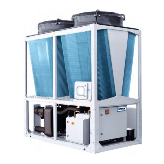
FORM NO.:6U6K-B01E-NB-EN SECTION 2 – PRODUCT DESCRIPTION UNIT COMPONENTS YMAA/YMPA0045-0065 Coils Control and Optiview LT Panel Compressors Brazed Plate Driver Panel Heat Exchanger Accumulator Receiver Transformer FIGURE 4 – COMPONENTS YMAA/YMPA0045-0065 JOHNSON CONTROLS Cooke Industries - Phone: +64 9 579 2185 Email: sales@cookeindustries.co.nz Web: www.cookeindustries.co.nz... - Page 19 FORM NO.: 6U6K-B01E-NB-EN SECTION 2 – PRODUCT DESCRIPTION UNIT COMPONENTS – YMAA/YMPA0080-0100 Fan 2 Fan 1 Coil s Brazed Plate Heat Exchanger Driver Panel Transformer Control Panel HMI Panel Compressors Accumulators FIGURE 5 – COMPONENTS YMAA/YMPA0080-0100 JOHNSON CONTROLS Cooke Industries - Phone: +64 9 579 2185 Email: sales@cookeindustries.co.nz Web: www.cookeindustries.co.nz...
- Page 20 FORM NO.:6U6K-B01E-NB-EN SECTION 2 – PRODUCT DESCRIPTION UNIT COMPONENTS – YMAA/YMPA0130 Fan 2 Fan 1 Coil s Brazed Plate Heat Exchanger Driver Panel Transformer Control Panel Optiview LT Panel Compressors Accumulators FIGURE 6 – COMPONENTS YMAA/YMPA0130 JOHNSON CONTROLS Cooke Industries - Phone: +64 9 579 2185 Email: sales@cookeindustries.co.nz Web: www.cookeindustries.co.nz...
- Page 21 FORM NO.: 6U6K-B01E-NB-EN SECTION 2 – PRODUCT DESCRIPTION UNIT COMPONENTS - YMAA/YMPA0160-0200 Fan 2 Fan 1 Fan 3 Coils Transformer Control and Compressors Optiview LT Panel Accumulators FIGURE 7 – COMPONENTS YMAA/YMPA0160-0200 JOHNSON CONTROLS Cooke Industries - Phone: +64 9 579 2185 Email: sales@cookeindustries.co.nz Web: www.cookeindustries.co.nz...
- Page 22 FORM NO.:6U6K-B01E-NB-EN SECTION 2 – PRODUCT DESCRIPTION UNIT COMPONENTS - YMAA/YMPA0230-0260 Fan 1 Fan 2 Fan 4 Coils Fan 3 Accumulators Compressors Control Panel Optiview LT Panel FIGURE 8 – COMPONENTS YMAA/YMPA0230-0260 JOHNSON CONTROLS Cooke Industries - Phone: +64 9 579 2185 Email: sales@cookeindustries.co.nz Web: www.cookeindustries.co.nz...
- Page 23 FORM NO.: 6U6K-B01E-NB-EN SECTION 2 – PRODUCT DESCRIPTION UNIT COMPONENTS - YMAA/YMPA0045-0065 HYDRO KIT VSD Pump Strainer Connect to Unit Air Purger Drainage Valves Expansion Tank Shutoff Valves FIGURE 9 – YMAA/YMPA0045-0065 HYDRO KIT (SINGLE PUMP) UNIT COMPONENTS - YMAA/YMPA0080-0130KW HYDRO KIT Strainer VSD Pump Connect to...
- Page 24 FORM NO.:6U6K-B01E-NB-EN SECTION 2 – PRODUCT DESCRIPTION UNIT COMPONENTS - YMAA/YMPA0160-0260 HYDRO KIT Strainer Expansion Tanks Shutoff Valves User Connections VSD Pump Drainage Valves FIGURE 11 – YMAA/YMPA0160-0260 HYDRO KIT (SINGLE PUMP) JOHNSON CONTROLS Cooke Industries - Phone: +64 9 579 2185 Email: sales@cookeindustries.co.nz Web: www.cookeindustries.co.nz...
- Page 25 UNIT DESIGNATOR PIN9 Premium efficiency REFRIGERANT PIN10 R410A VOLTAGE PIN11-12 400/3/50 BRANDING KITS PIN13 York branding kits Copper tube aluminum fin coils COIL DESIGN PIN14 Special Quote Optiview LT HMI Controller OPERATION DISPLAY PIN15 Indoor wire controller POWER FIELD PIN16/17...
- Page 26 FORM NO.:6U6K-B01E-NB-EN SECTION 2 – PRODUCT DESCRIPTION TABLE 1 – PRODUCT IDENTIFICATION NUMBER (PIN) (CONT’D) FEATURE PIN NUMBER OPTION OPTION DESCRIPTION WATER PIPE CONNECTION TYPE PIN 27 Groove connection with victaulic kits FLOW SWITCH PIN 28 One Paddle type Flow Switch per unit PRESSURE VESSEL CODE PIN 29 PED Pressure Vessel Codes...
-
Page 27: Section 3 - Handling And Storage
FORM NO.: 6U6K-B01E-NB-EN SECTION 2 – PRODUCT DESCRIPTION SECTION 3 – HANDLING AND STORAGE Rigging and lifting should only be done by a DELIVERY AND STORAGE professional rigger in accordance with a written To ensure consistent quality and maximum reliability, all units rigging and lifting plan. -
Page 28: Operating And Storage Conditions
FORM NO.:6U6K-B01E-NB-EN SECTION 3 – HANDLING AND STORAGE • For models of YMAA/YMPA 0160-0260, forklift truck for The condensers should be covered to protect the coils and fins from potential damage and corrosion, particularly where moving the unit is NOT recommended. building work is in progress. - Page 29 FORM NO.: 6U6K-B01E-NB-EN SECTION 3 – HANDLING AND STORAGE Rigging Plates Wooden Pallet FIGURE 14 – RIGGING PLATES YMAA/YMPA0045-0130 Notes The rigging plates are factory mounted. For models of YMAA/YMPA 0160-0260, the rigging plates are factory mounted. The forklift holes on base frame unit is not recommended for moving unit by forklift trucks.
- Page 30 FORM NO.:6U6K-B01E-NB-EN SECTION 3 – HANDLING AND STORAGE Dragging Plate (Factory-Mounted) Rigging Plate (Factory-Mounted) Anticollision Plate Forklift Hole (Factory-Mounted) FIGURE 15 – RIGGING PLATES YMAA/YMPA0160-0260 Notes 1.Dragging plates and anticollision plates are only used during container transport; 2.Forklift holes are for in-plant transfer; 3.Four rigging plates are installed before delivery.
-
Page 31: Section 4 - Installation
A written request for inspection by the carrier’s agent should be authorized YORK service mechanic or a qualified made at once. service person experienced in unit installation. -
Page 32: Isolators (Optional)
Unit noise is a result of compressor adjusted at installation of the unit. and fan operation. Considerations should be made utilizing noise levels published in the YORK Engineering Guide for the CHILLED LIQUID PIPING General – When the unit(s) has been located in its final specific unit model. -
Page 33: Pipework Arrangement
FORM NO.: 6U6K-B01E-NB-EN SECTION 4 – INSTALLATION Consideration should be given to compressor and control panel free it from foreign material before the system is placed into access when laying out water piping. Routing the water piping operation. Use care not to flush any foreign material into or too close to the unit could make compressor/ control panel through the cooler. - Page 34 FORM NO.:6U6K-B01E-NB-EN SECTION 4 – INSTALLATION Expansion Air Purger Tank Pump Strainer Strainer Heaters Shut-off Valve Drainage Valve Flow Switch Drainage Valve Shut-off Valve YMAA/YMPA0045-0130 Air Purger Expansion Air Purger Tank Flow Switch Pump Strainer PHE1 PHE2 Heaters Shut-off Valve Drainage Valve Shut-off...
- Page 35 2.Site restrictions may compromise minimum clearances indicated below, resulting in unpredictable air flow patterns 6.Stop valves must be installed at the inlet of each unit to and possible diminished performance. York's unit controls balance chilled liquid distribution. will optimize operation without nuisance high pressure safety cutout;...
-
Page 36: Wiring
FORM NO.:6U6K-B01E-NB-EN SECTION 4 – INSTALLATION The pump will not run if the micro panel has been powered WIRING The units are shipped with all factory-mounted controls wired up for less than 30 seconds, or if the pump has run in the last for operation. -
Page 37: Circuit Breaker
BAS protocols. It efficiently manages all of the communication protocols used by York equipment, exposing the data in a consistent, organized, and defined fashion. BPHE AND PIPING HEATERS Heat exchanger and piping heaters will be switched on in standby mode when air temperature is below 3 °C. -
Page 38: Power Supply Connection
FORM NO.:6U6K-B01E-NB-EN SECTION 4 – INSTALLATION POWER SUPPLY CONNECTION Electrical Legends TABLE 2 - ABBREVIATIONS OF ELECTRICAL COMPONENTS CODE DESCRIPTION CODE DESCRIPTION CODE DESCRIPTION -YMEV MAIN EEV COMPR MOTOR -FHP HIGH PRESS SWITCH -YWSV WATER SOL VALVE -KWP WATER PUMP RELAY -EPH WATER PIPING HEATER -YMSV... - Page 39 FORM NO.: 6U6K-B01E-NB-EN SECTION 4 – INSTALLATION Power Supply Connection – Modular FIGURE 21 – MODULAR POWER SUPPLY CONNECTION JOHNSON CONTROLS Cooke Industries - Phone: +64 9 579 2185 Email: sales@cookeindustries.co.nz Web: www.cookeindustries.co.nz...
- Page 40 FORM NO.:6U6K-B01E-NB-EN SECTION 4 – INSTALLATION Notes 3.The maximum quantity of modules above 130 kW 1.Power wiring must be provided through a protect device (fused combined should be 16. The quantity of modules in the same disconnect switch or circuit breaker) to the input terminals of communication network is based on the sum total of control the unit in accordance with CE or local code requirements.
-
Page 41: Control Wiring
FORM NO.: 6U6K-B01E-NB-EN SECTION 4 – INSTALLATION CONTROL WIRING Communication Wiring – Optiview LT FIGURE 22 – OPTIVIEW LT COMMUNICATION WIRING Communication Wiring – Wire Controller FIGURE 23 – WIRE CONTROLLER COMMUNICATION WIRING Note Optiview LT can be rewired to CON203 if wire controller is connected. TABLE 3 –... - Page 42 FORM NO.:6U6K-B01E-NB-EN SECTION 4 – INSTALLATION Notes 1 . T h e t ot al l e ng th o f t h e c o m m u n i c at i o n cab le L = communication network is based on the sum total of control L1+L2+L3...+Ln.
-
Page 43: Section 5 - Technical Data
FORM NO.: 6U6K-B01E-NB-EN SECTION 4 – INSTALLATION SECTION 5 – TECHNICAL DATA OPERATIONAL LIMITATIONS TABLE 4 – TEMPERATURES AND FLOWS (COOLING CONDITION, CHILLER AND HEAT PUMP) LEAVING WATER YMAA LIQUID FLOW (L/S) AIR ON CONDENSER (°C) TEMPERATURE (°C) YMPA LEAVING WATER YMAA LIQUID FLOW (L/S) AIR ON CONDENSER (°C) - Page 44 FORM NO.:6U6K-B01E-NB-EN SECTION 5 – TECHNICAL DATA TABLE 6 – TEMPERATURES AND FLOWS (COOLING CONDITION, MEDIUM TEMPERATURE PROCESS CHILLER) LEAVING WATER LIQUID FLOW (L/S) AIR ON CONDENSER (°C) YMAA TEMPERATURE (°C) 0045 -17.8 0065 -17.8 0080 -17.8 0100 -17.8 0130 -17.8 0160 11.1...
-
Page 45: Operational Limitations
FORM NO.: 6U6K-B01E-NB-EN SECTION 5 – TECHNICAL DATA OPERATIONAL LIMITATIONS OPERATIONAL LIMITATIONS HEAT EXCHANGER PRESSURE DROP HEAT EXCHANGER PRESSURE DROP PRESSURE YMAA/YMPA CORRELATION DROP CURVE 0045 y = 1.4169*x^3 - 2.7902*x^2 + 18.488*x - 9.0295 0065 y = 0.1071*x^3 + 1.3526*x^2 + 4.525*x - 3.4853 0080 y = -0.1316*x^3 + 3.4848*x^2 - 6.0541*x + 7.4083 0100... - Page 46 FORM NO.:6U6K-B01E-NB-EN SECTION 5 – TECHNICAL DATA PHYSICAL DATA TABLE 8 - PHYSICAL DATA (YMAA/YMPA0045-0130) YMAA/YMPA Model 0045PE 0065PE 0080PE 0100PE 0130PE Type DC inverter scroll and fixed speed scroll Compressor Quantity EC motor Fan Motor Type Fan Qty Working ambient Air side heat °C -17.8~48...
-
Page 47: Physical Data
FORM NO.: 6U6K-B01E-NB-EN SECTION 5 – TECHNICAL DATA TABLE 9 - PHYSICAL DATA (YMAA/YMPA0160-0260) YMAA/YMPA Model 0160PE 0200PE 0230PE 0260PE Type DC inverter scroll and fixed speed scroll Compressor Quantity Fan Motor Type EC motor Fan Qty Working ambient temp. Air side heat -17.8~48 -17.8~48... - Page 48 SECTION 5 – TECHNICAL DATA FORM NO.:6U6K-B01E-NB-EN TABLE 10 - REFRIGERANT AND OIL CHARGE YMAA/YMPA 0045 0065 0080 0100 0130 0160 0200 0230 0260 SYS1 12.3 11.4 11.4 Refrigerant SYS2 9.05 11.4 10.5 11.4 Charge SYS3 10.5 11.4 11.4 SYS4 11.4 11.4 Tonnes of CO...
-
Page 49: Electrical Data
FORM NO.: 6U6K-B01E-NB-EN SECTION 5 – TECHNICAL DATA ELECTRICAL DATA TABLE 11 - YMAA ELECTRICAL DATA (WITHOUT HYDRO KIT) YMAA 0045PE 0065PE 0080PE 0100PE 0130PE Nominal Voltage/Voltage Limits 400V-3PH-50Hz/360V-440V Nominal Current at 400V (A) 25.7 36.2 40.6 55.0 70.6 Max Current at 400V (A) 35.1 38.3 60.9... - Page 50 FORM NO.:6U6K-B01E-NB-EN SECTION 5 – TECHNICAL DATA TABLE 16 - YMPA ELECTRICAL DATA (WITHOUT HYDRO KIT) YMPA 0160PE 0200PE 0230PE 0260PE Nominal Voltage/Voltage Limits 400V-3PH-50Hz/360V-440V Nominal Current at 400V (A) 96.4 107.8 139.0 148.6 Max Current at 400V (A) 119.5 133.1 166.4 179.9...
-
Page 51: Electrical Diagram
FORM NO.: 6U6K-B01E-NB-EN SECTION 5 – TECHNICAL DATA ELECTRICAL DIAGRAM All electrical wiring should be carried out in accordance with power supply terminals on the unit. local regulations. Route properly sized cables to the cable entries in the bottom of the power panel. To ensure that no eddy currents are set up in the power panel, the cables forming each 3 phase power supply must enter via It is the responsibility of the user to install over current... -
Page 52: Wiring Diagram
FORM NO.:6U6K-B01E-NB-EN SECTION 5 – TECHNICAL DATA WIRING DIAGRAM YMAA/YMPA0045-0065 FIGURE 26 – YMAA/YMPA0045-0065 WIRING DIAGRAM JOHNSON CONTROLS Cooke Industries - Phone: +64 9 579 2185 Email: sales@cookeindustries.co.nz Web: www.cookeindustries.co.nz... - Page 53 FORM NO.: 6U6K-B01E-NB-EN SECTION 5 – TECHNICAL DATA FIGURE 27 – YMAA/YMPA0045-0065 MICROBOARD WIRING DIAGRAM JOHNSON CONTROLS Cooke Industries - Phone: +64 9 579 2185 Email: sales@cookeindustries.co.nz Web: www.cookeindustries.co.nz...
- Page 54 SECTION 5 – TECHNICAL DATA FORM NO.:6U6K-B01E-NB-EN YMAA/YMPA0080-0130 FIGURE 28 – YMAA/YMPA0080-0130 WIRING DIAGRAM JOHNSON CONTROLS Cooke Industries - Phone: +64 9 579 2185 Email: sales@cookeindustries.co.nz Web: www.cookeindustries.co.nz...
- Page 55 SECTION 5 – TECHNICAL DATA FORM NO.: 6U6K-B01E-NB-EN FIGURE 29 – YMAA/YMPA0080-0130 MICROBOARD WIRING DIAGRAM JOHNSON CONTROLS Cooke Industries - Phone: +64 9 579 2185 Email: sales@cookeindustries.co.nz Web: www.cookeindustries.co.nz...
- Page 56 SECTION 5 – TECHNICAL DATA FORM NO.:6U6K-B01E-NB-EN YMAA/YMPA0160-0260 JOHNSON CONTROLS Cooke Industries - Phone: +64 9 579 2185 Email: sales@cookeindustries.co.nz Web: www.cookeindustries.co.nz...
- Page 57 SECTION 5 – TECHNICAL DATA FORM NO.: 6U6K-B01E-NB-EN FIGURE 30 – YMAA/YMPA0160-0260 WIRING DIAGRAM JOHNSON CONTROLS Cooke Industries - Phone: +64 9 579 2185 Email: sales@cookeindustries.co.nz Web: www.cookeindustries.co.nz...
- Page 58 FORM NO.:6U6K-B01E-NB-EN SECTION 5 – TECHNICAL DATA JOHNSON CONTROLS Cooke Industries - Phone: +64 9 579 2185 Email: sales@cookeindustries.co.nz Web: www.cookeindustries.co.nz...
- Page 59 FORM NO.: 6U6K-B01E-NB-EN SECTION 5 – TECHNICAL DATA FIGURE 31 – YMAA/YMPA0160-0260 MICROBOARD WIRING DIAGRAM JOHNSON CONTROLS Cooke Industries - Phone: +64 9 579 2185 Email: sales@cookeindustries.co.nz Web: www.cookeindustries.co.nz...
- Page 60 FORM NO.:6U6K-B01E-NB-EN FIGURE 32 – YMAA/YMPA0045-0130 FIXED SPEED PUMP WIRING DIAGRAM Notes 1.Main power is connected to micro breaker QCB4 in control panel; 2.Control power is connected to both ends of the relay (KWP) coil in control panel; 3.Pump PTO is connected to XTB2: 80E&85 for system flow switch SF2. JOHNSON CONTROLS Cooke Industries - Phone: +64 9 579 2185 Email: sales@cookeindustries.co.nz...
- Page 61 FORM NO.: 6U6K-B01E-NB-EN FIGURE 33 – COMMUNICATION AND SC-EQ WIRING Notes 1.Refer to installation commissioning operation and 6.Model solenoid valve -YMSV only for heat pump. maintenance manual for customer connections and notes. Non- 7.Low pressure switch -FLP*2 only for heat pump. compliance to these instructions will invalidate unit warranty.
- Page 62 SECTION 5 – TECHNICAL DATA FORM NO.:6U6K-B01E-NB-EN THIS PAGE INTENTIONALLY LEFT BLANK. JOHNSON CONTROLS Cooke Industries - Phone: +64 9 579 2185 Email: sales@cookeindustries.co.nz Web: www.cookeindustries.co.nz...
-
Page 63: Dip Switch Setting
SECTION 5 – TECHNICAL DATA FORM NO.: 6U6K-B01E-NB-EN DIP SWITCH SETTING DIP SWITCH SETTING Microboard DIP Switch Two DIP switches, SW301 and SW302, are located on the IPU3 micro board. SW301 is an eight-digit switch and the first five digits are used to set communication addresses for each module. - Page 64 SECTION 5 – TECHNICAL DATA FORM NO.:6U6K-B01E-NB-EN Wire Controller DIP Switch The other digits of SW302, except for SW302-1, are used to set The 6-digit switch used to set the unit type is positioned in the the configurations of the unit. This is already finished before back of the wire controller.
-
Page 65: Dimensions
SECTION 5 – TECHNICAL DATA FORM NO.: 6U6K-B01E-NB-EN DIMENSIONS DIMENSIONS YMAA/YMPA0045-0065 (WITHOUT HYDRO KIT) YMAA/YMPA0045-0065 (WITHOUT HYDRO KIT) JOHNSON CONTROLS Cooke Industries - Phone: +64 9 579 2185 Email: sales@cookeindustries.co.nz Web: www.cookeindustries.co.nz... - Page 66 SECTION 5 – TECHNICAL DATA FORM NO.:6U6K-B01E-NB-EN YMAA/YMPA0045-0065 (WITH HYDRO KIT) JOHNSON CONTROLS Cooke Industries - Phone: +64 9 579 2185 Email: sales@cookeindustries.co.nz Web: www.cookeindustries.co.nz...
- Page 67 1" nominal deflection isolators (not and possible diminished performance. YORK’s unit controls shown) will increase overall unit height by 150mm. will optimize operation without nuisance high-pressure safety cutouts;...
- Page 68 FORM NO.:6U6K-B01E-NB-EN YMAA/YMPA0080-0130 (WITHOUT HYDRO KIT) JOHNSON CONTROLS Cooke Industries - Phone: +64 9 579 2185 Email: sales@cookeindustries.co.nz Web: www.cookeindustries.co.nz...
- Page 69 SECTION 5 – TECHNICAL DATA FORM NO.: 6U6K-B01E-NB-EN YMAA/YMPA0080-0130 (WITH HYDRO KIT) JOHNSON CONTROLS Cooke Industries - Phone: +64 9 579 2185 Email: sales@cookeindustries.co.nz Web: www.cookeindustries.co.nz...
- Page 70 Piping System Connections. No more than one adjacent wall and possible diminished performance. YORK’s unit controls may be higher than the unit. 1" nominal deflection isolators (not will optimize operation without nuisance high-pressure safety shown) will increase overall unit height by 150mm.
- Page 71 FORM NO.: 6U6K-B01E-NB-EN SECTION 5 – TECHNICAL DATA YMAA/YMPA0160-0200 (WITHOUT HYDRO KIT) JOHNSON CONTROLS Cooke Industries - Phone: +64 9 579 2185 Email: sales@cookeindustries.co.nz Web: www.cookeindustries.co.nz...
- Page 72 Piping System Connections. No more than one adjacent wall and possible diminished performance. YORK’s unit controls may be higher than the unit. 1" nominal deflection isolators (not will optimize operation without nuisance high-pressure safety shown) will increase overall unit height by 150mm.
- Page 73 FORM NO.: 6U6K-B01E-NB-EN YMAA/YMPA0230-0260 (WITHOUT HYDRO KIT) JOHNSON CONTROLS Cooke Industries - Phone: +64 9 579 2185 Email: sales@cookeindustries.co.nz Web: www.cookeindustries.co.nz...
- Page 74 Piping System Connections. No more than one adjacent wall and possible diminished performance. YORK’s unit controls may be higher than the unit. 1" nominal deflection isolators (not will optimize operation without nuisance high-pressure safety shown) will increase overall unit height by 150mm.
-
Page 75: Technical Data - Clearances
SECTION 5 – TECHNICAL DATA FORM NO.: 6U6K-B01E-NB-EN TECHNICAL DATA – CLEARANCES YMAA/YMPA0080-0130 (WITHOUT HYDRO KIT) ≥ ≥ ≥ ≥ Notes 1.The figure above uses 130 kW unit as an example but also applies to all models; 2.No obstructions allowed above the unit; 3.Only one adjacent wall may be higher than the unit. -
Page 76: Isolators - Weight Distribution And Isolator Mounting Positions
SECTION 5 – TECHNICAL DATA FORM NO.:6U6K-B01E-NB-EN ISOLATORS – WEIGHT DISTRIBUTION AND ISOLATOR MOUNTING POSITIONS GENERAL TABLE 24 - GRAVITY CENTER OF STANDARD UNIT Weights of specific unit models vary significantly as options are Gravity Center (mm) YMAA/YMPA added. As a result, total weights, weights at individual isolator Without Hydro Kit positions, and actual isolator selection at each position cannot 0045... - Page 77 SECTION 5 – TECHNICAL DATA FORM NO.: 6U6K-B01E-NB-EN AVM COORDINATES AND WEIGHT “SAMPLE PRINTOUT” TYPICAL OF THE INFORMATION SUPPLIED IN THE MASS DISTRIBUTION LABEL FIGURE 41 – COODINATE LOCATIONS JOHNSON CONTROLS Cooke Industries - Phone: +64 9 579 2185 Email: sales@cookeindustries.co.nz Web: www.cookeindustries.co.nz...
- Page 78 SECTION 5 – TECHNICAL DATA FORM NO.:6U6K-B01E-NB-EN TABLE 26 - COORDINATES YMAA Options Description Coordinate YMPA Conditions Base Model 34(X) (X,Y) (307, 39) (1193, 39) 0045PE Single VSD Pump, standard head 34(A) (X,Y) (307, 39) (1193, 39) (1995, 39) Base Model 34(X) (X,Y) (307, 39)
- Page 79 SECTION 5 – TECHNICAL DATA FORM NO.: 6U6K-B01E-NB-EN TABLE 27 - AVM WEIGHT YMAA Options Description Weight YMPA Conditions Base Model 34(X) 0045PE Single VSD Pump, standard head 34(A) Base Model 34(X) 0065PE Single VSD Pump, standard head 34(A) Base Model 34(X) 0080PE Single VSD Pump, standard head...
-
Page 80: Isolator Details - One Inch Deflection Spring Isolator Cross-Reference
SECTION 5 – TECHNICAL DATA FORM NO.:6U6K-B01E-NB-EN ISOLATOR DETAILS – ONE INCH DEFLECTION SPRING ISOLATOR CROSS-REFERENCE Outline Drawing - Type MHS Isolators Technical Data - Type MHS Isolators OUTER SIZE( ±2mm) VERTICAL LOAD LOAD DEFLECTION( RIGIDITY MODEL mm) (kg) (N) (kg/mm) 6.40 MHS-160... - Page 81 SECTION 5 – TECHNICAL DATA FORM NO.: 6U6K-B01E-NB-EN ISOLATOR DETAILS – ONE INCH DEFLECTION SPRING ISOLATOR CROSS-REFERENCE Outline Drawing - Type MHD Isolators Technical Data - Type MHD Isolators OUTER SIZE (±2mm) VERTICAL LOAD LOAD DEFLECTION RIGIDITY MODEL (kg) (mm) (kg/mm) 22.00 MHD-550...
- Page 82 SECTION 5 – TECHNICAL DATA FORM NO.:6U6K-B01E-NB-EN ISOLATOR TYPES YMAA Options Description PIN Conditions YMPA Base Model 34(X) MHS-200 MHS-200 0045PE Single VSD Pump, standard head 34(A) MHS-230 MHS-160 MHS-160 Base Model 34(X) MHS-200 MHS-200 0065PE Single VSD Pump, standard head 34(A) MHS-230 MHS-160...
-
Page 83: One Inch Deflection - Spring Isolators Installation Instructions
SECTION 5 – TECHNICAL DATA FORM NO.: 6U6K-B01E-NB-EN ONE INCH DEFLECTION – SPRING ISOLATORS INSTALLATION INSTRUCTIONS Installation Instructions 6.Place the fixing bolt and washer but do not tighten them. 1.Read instructions in their entirety before beginning installation. 7.Ensure the verticality of the isolators and use bolts to fix the bases of the isolators to the level floor. -
Page 84: Two Inch Deflection Spring Isolator Cross-Reference
SECTION 5 – TECHNICAL DATA FORM NO.:6U6K-B01E-NB-EN TWO INCH DEFLECTION SPRING ISOLATOR CROSS- REFERENCE Outline Drawing – Type LAT Isolators Technical Data - Type LAT Isolators OUTER SIZE( ±2mm) VERTICAL LOAD LOAD DEFLECTION RIGIDITY MODEL (kg) (N) (mm) (kg/mm) 3.20 LAT-160 1568 LAT-180... - Page 85 SECTION 5 – TECHNICAL DATA FORM NO.: 6U6K-B01E-NB-EN Outline Drawing – Type LAT2 Isolators Technical Data - Type LAT2 Isolators OUTER SIZE (±2mm) VERTICAL LOAD LOAD DEFLECTION RIGIDITY MODEL (kg) (mm) (kg/mm) 5.60 LAT2-280 2744 6.40 LAT2-320 3136 7.20 LAT2-360 3528 M10X30 M20X60 45~50...
- Page 86 SECTION 5 – TECHNICAL DATA FORM NO.:6U6K-B01E-NB-EN ISOLATOR PART NUMBERS YMAA Options Description PIN Conditions YMPA Base Model 34(X) LAT-200 LAT-200 0045PE Single VSD Pump, standard head 34(A) LAT-230 LAT-160 LAT-160 Base Model 34(X) LAT-200 LAT-200 0065PE Single VSD Pump, standard head 34(A) LAT-230 LAT-160...
-
Page 87: Two Inch Deflection Spring Isolator Installation And Adjustment
SECTION 5 – TECHNICAL DATA FORM NO.: 6U6K-B01E-NB-EN TWO INCH DEFLECTION SPRING ISOLATOR INSTALLATION AND ADJUSTMENT Installation Instructions 6.Place the fixing bolt and washer but do not tighten them. 1.Read instructions in their entirety before beginning installation. 7.Ensure the verticality of the isolators and use bolts to fix the bases of the isolators to the level floor. -
Page 88: Neoprene Isolator Cross-Reference
SECTION 5 – TECHNICAL DATA FORM NO.:6U6K-B01E-NB-EN NEOPRENE ISOLATOR CROSS-REFERENCE Outline Drawing – Type JD Isolators Technical Data – Type JD Isolators OUTER SIZE( ±2mm) VERTICAL LOAD LOAD DEFLECTION RIGIDITY MODEL (kg) (N) (mm) (kg/mm) 16.00 JD-160 1568 20.00 JD-200 1960 6~12 M12X30... - Page 89 SECTION 5 – TECHNICAL DATA FORM NO.: 6U6K-B01E-NB-EN NEOPRENE ISOLATOR CROSS-REFERENCE Outline Drawing - Type JR Isolators Technical Data - Type JR Isolators OUTER SIZE (±2mm) VERTICAL LOAD LOAD DEFLECTION RIGIDITY MODEL (kg) (mm) (kg/mm) 150.00 5880 JR-600 175.00 JR-700 6860 2~4 200.00...
- Page 90 SECTION 5 – TECHNICAL DATA FORM NO.:6U6K-B01E-NB-EN ISOLATOR TYPES ISOLATOR TYPES YMAA Options Description PIN Conditions YMPA Base Model 34(X) JD-200 JD-200 0045PE Single VSD Pump, standard head 34(A) JD-240 JD-160 JD-160 Base Model 34(X) JD-200 JD-200 0065PE Single VSD Pump, standard head 34(A) JD-240 JD-160...
-
Page 91: Neoprene Isolator Installation And Adjustment
SECTION 5 – TECHNICAL DATA FORM NO.: 6U6K-B01E-NB-EN NEOPRENE ISOLATOR INSTALLATION AND ADJUSTMENT Installation Instructions a level surface. Leveling all isolator bases to the same elevation. 1.Read instructions in their entirety before beginning installation. 5.Place equipment on top of isolators making sure that mounting holes of the equipment line up with isolator 2.Isolators are shipped fully assembled. - Page 92 FORM NO.:6U6K-B01E-NB-EN SECTION 5 – TECHNICAL DATA THIS PAGE INTENTIONALLY LEFT BLANK. JOHNSON CONTROLS Cooke Industries - Phone: +64 9 579 2185 Email: sales@cookeindustries.co.nz Web: www.cookeindustries.co.nz...
-
Page 93: Section 6 - Commissioning
Perform the commissioning using the detailed checks outlined in the START-UP CHECK LIST as the commissioning procedure To add oil to a circuit – connect a YORK hand oil pump to the is carried out. 1/4” oil charging connection before the accumulator with a length of clean hose or copper line, but do not tighten the flare PREPARATION –... -
Page 94: Preparation - Power On
FORM NO.:6U6K-B01E-NB-EN SECTION 6 – COMMISSIONING the terminal blocks or circuit breaker. Ensure that connections Flow rates and pressure drops must be within the limits given of power cables within the panels to the circuit breaker or in the Technical Data section. Operation outside of these limits terminal blocks are tight. - Page 95 SECTION 6 – COMMISSIONING FORM NO.: 6U6K-B01E-NB-EN YMPA0045-0260 YMAA0045-0260 INSTALL CONFIDENCE START-UP CHECKLIST JOB NAME: CUSTOMER: LOCATION: ADDRESS: CUSTOMER ORDER NO: PHONE: JCI ORDER NO: JCI CONTRACT NO: JCI TEL NO: UNIT MODEL NO: UNIT SERIAL NO: The work (as checked below) is in process and will be completed by: Month Year The following work must be completed in accordance with installation instructions:...
- Page 96 SECTION 6 – COMMISSIONING FORM NO.:6U6K-B01E-NB-EN C. PANEL CHECKS (POWER ON - BOTH UNIT SWITCH OFF) Display Language Date and Time 1.Apply 3-phase power and verify its value. SYSTEM SETPOINTS Voltage imbalance should be no more than 2% □ Unit Type of the average voltage.
- Page 97 YORK Guangzhou Air Conditioning & Refrigeration Co., Ltd 800-861-1001 Subject to change without notice. Printed in China Copyright © by Johnson Controls 2017 www.johnsoncontrols.com...
-
Page 98: Unit Operating Sequence
FORM NO.:6U6K-B01E-NB-EN SECTION 6 – COMMISSIONING UNIT OPERATING SEQUENCE superheat. There is a pre-adjustment of the opening before The operating sequence described below relates to operation on compressor loading up or shutting down within one refrigerant a starting process after power has been applied, such as start-up circuit. -
Page 99: Control Modes
SECTION 6 – COMMISSIONING FORM NO.: 6U6K-B01E-NB-EN low pressure centrifugal pumps with flange connection and with the volume flow. mechanical seal. Q = Volume flow CONTROL MODES H = Differential pressure (min./max.) The selectable control modes are: HS = Differential pressure setpoint Δp-c: Manual control mode: The speed of the pump can be kept to a constant speed between... -
Page 100: Mode Setting
SECTION 6 – COMMISSIONING FORM NO.:6U6K-B01E-NB-EN MODE SETTING continuous system deviation is avoided. Δp-c/Δp-v control: The D (or derivative) term responds directly to the rate of Setting Δp-c Δp-v change of the system deviation. This affects the rate at which Starting at the duty Starting at the duty the system responds. -
Page 101: Operation
SECTION 6 – COMMISSIONING FORM NO.: 6U6K-B01E-NB-EN • Switch 1 is for switching between the standard and service mode. • Switch 2 allows activations or deactivation of the access disable feature. • Switches 3 and 4 permit termination of the multi-pump communication. -
Page 102: Section 7 - Optiview Lt Operation
SECTION 7 – OPTIVIEW LT OPERATION FORM NO.:6U6K-B01E-NB-EN SECTION 7 – OPTIVIEW LT OPERATION Area 1: System operating status; INTRODUCTION Area 2: Functions; The 7 inch resistive touch screen HMI is used to configure unit Area 3: Date and time; running parameters and for readout. -
Page 103: System Setpoints
SECTION 7 – OPTIVIEW LT OPERATION FORM NO.: 6U6K-B01E-NB-EN This is used for system running status readout. The following parameters will be displayed in order: Chiller Status Chiller Loading Low Noise Operating Mode Available Mode Pump Status Chiller Return Temperature Total Run Hours Comp. -
Page 104: Unit
SECTION 7 – OPTIVIEW LT OPERATION FORM NO.:6U6K-B01E-NB-EN Confirm Action: Infilling: UNIT Selection unit to view the operating status of different modules in the network. The following parameters will appear in order: Unit Selection Ckt1 Suct Pr Unit Water Valve Unit Network Status Ckt2 Suct Pr Ckt1 Fan Motor... -
Page 105: Fault
SECTION 7 – OPTIVIEW LT OPERATION FORM NO.: 6U6K-B01E-NB-EN Detailed information is accessible by pressing the faults, except FAULT This is for fault readout and reset. There will be an about for communication fault between HMI and the units. 6-second delay while entering the interface, caused by the information reading from the mainboard. -
Page 106: Hmi
SECTION 7 – OPTIVIEW LT OPERATION FORM NO.:6U6K-B01E-NB-EN Use “Unit Selection” to switch between the units if modular Viewer’s interface connected. Operator’s interface In Service level, the faults can be reset and cleared. Service’s interface The settings relate to HMI displays and software upgrades are available under this menu. -
Page 107: Schedule
SECTION 7 – OPTIVIEW LT OPERATION FORM NO.: 6U6K-B01E-NB-EN Date and time setting: Press the “Reset Schedule” button to clear all schedule settings. The password change for “Operator” is available by pressing the “Security” button. Holiday Setting Service password reset and software upgrade are accessible in The Holiday Setting is used to set specified dates as holidays. - Page 108 SECTION 7 – OPTIVIEW LT OPERATION FORM NO.:6U6K-B01E-NB-EN Forced Action Unit EEV Forced Step INV Forced Frequency Select Forced EEV Force Command Option Fan1 Motor Forced Speed EEV Returns to Zero DO1 - DO32 Fan2 Motor Forced Speed JOHNSON CONTROLS Cooke Industries - Phone: +64 9 579 2185 Email: sales@cookeindustries.co.nz Web: www.cookeindustries.co.nz...
-
Page 109: Section 8 - Wire Controller Operation
SECTION 8 – WIRE CONTROLLER OPERATION FORM NO.: 6U6K-B01E-NB-EN SECTION 8 – WIRE CONTROLLER OPERATION INTRODUCTION Don’t touch the screen with sharp points or edges The touch screen wire controller is optional for remote controls which may damage the controller. Don’t twist or pull of YMAA/YMPA units. -
Page 110: Basic Operations
SECTION 8 – WIRE CONTROLLER OPERATION FORM NO.:6U6K-B01E-NB-EN TABLE 30 – HMI DISPLAY PRIVILEGE LEVELS K E Y M E A N IN G K E Y M E A N IN G K E Y M E A N IN G COOLING FUNCTION FAULT... - Page 111 SECTION 8 – WIRE CONTROLLER OPERATION FORM NO.: 6U6K-B01E-NB-EN In Timer Mode setting, press “FUNCTION” to switch The setting will terminate if there’s no operation for 5 seconds the modes between ONCE, DAILY and WEEKLY. Press or “CANCEL” is pressed. “CONFIRM”...
-
Page 112: Section 9 - Unit Operation
SECTION 9 – UNIT OPERATION FORM NO.:6U6K-B01E-NB-EN SECTION 9 – UNIT OPERATION CAPACITY CONTROL If the suction pressure drops lower, the unit will unload to To initiate the start sequence of the unit, all run permissive prevent unexpected shutdown. The limitations are listed in inputs must be satisfied (liquid flow, remote start/stop switch, Table 32. -
Page 113: Discharge Temperature Controls
SECTION 9 – UNIT OPERATION FORM NO.: 6U6K-B01E-NB-EN pressures detected are measured by gauge pressure. The ratio The ratio limitations are listed in Table 36 when unload is must be kept in a certain range to make sure the compressor is mandatory. - Page 114 SECTION 9 – UNIT OPERATION FORM NO.:6U6K-B01E-NB-EN △Tw are applied herein. LIQUID TEMP. CONTROL The setpoint, when programmed for Return Liquid Temp. Control or Leaving Liquid Temp. Control, is the temperature Cooling: △Ts=Twi –Tset, △Tw=Twi –Twi-1 the unit will control to within +/- the (control) cooling or Heating: △Ts=Tset –Twi, △Tw=Twi-1 –Twi heating range.
-
Page 115: Liquid Temp. Control
SECTION 9 – UNIT OPERATION FORM NO.: 6U6K-B01E-NB-EN temperature changes toward setpoint rapidly, the compressor In cooling mode, the return chilled liquid setpoint is will not be allowed to load even if current temperature is still programmable from 10 °C to 25 °C in water chilling mode and not achieving the setpoint. -
Page 116: Variable Leaving Water Temperature Controls
SECTION 9 – UNIT OPERATION FORM NO.:6U6K-B01E-NB-EN setpoints to match the required cooling or heating load as VARIABLE LEAVING WATER TEMPERATURE CONT- ROLS ambient temperature changes. Four liquid temperature setpoints Variable Leaving Water Temperature Controls are applicable in cooling, and five setpoints in heating, are programmable to in water chilling mode and heating mode. -
Page 117: Compressor Sequencing
SECTION 9 – UNIT OPERATION FORM NO.: 6U6K-B01E-NB-EN The priorities while loading compressors are listed as follows: COMPRESSOR SEQUENCING The cumulative run time of each system is stored to help 1.Idle inverter compressor; equalize average run hours between systems with 2 refrigerant systems or in modular applications. -
Page 118: Defrost Controls
SECTION 9 – UNIT OPERATION FORM NO.:6U6K-B01E-NB-EN ignored. The compressors within the system will start with a 30 DEFROST CONTROLS The purpose of any defrost system is to remove frost and ice seconds delay. from the ambient coils. The adaptive defrost system achieves this by optimizing the setpoint of defrosts dependent on ambient The fan for the system will stop, except when the discharge temperature and duration with the aim of improving overall unit... -
Page 119: Anti-Recycle Timer
SECTION 9 – UNIT OPERATION FORM NO.: 6U6K-B01E-NB-EN If the sensor has to be repositioned it should remain in contact AUXILIARY HEATER CONTROL with the coil capillary and be placed adjacent to the coil end The field-mounted auxiliary heater will be powered on when plate which indicates the frost situations of the coils. -
Page 120: Section 10 - Service And Troubleshooting
SECTION 10 – SERVICE AND TROUBLESHOOTING FORM NO.:6U6K-B01E-NB-EN SECTION 10 – SERVICE AND TROUBLESHOOTING SERVICE MODE following inputs and outputs. Service Mode is a mode that allows the user to enable or disable all of the outputs on the unit, change configuration setup ANALOG AND DIGITAL INPUTS parameters and view all the inputs. -
Page 121: Digital/Pwm Outputs And Communications
SECTION 10 – SERVICE AND TROUBLESHOOTING FORM NO.: 6U6K-B01E-NB-EN DIGITAL/PWM OUTPUTS AND COMMUNICATIONS Table 40 is a quick reference list providing the description of the outputs and communication ports. All output and communication connections pertain to the connections at the microboard. TABLE 40 –... -
Page 122: Troubleshooting
SECTION 10 – SERVICE AND TROUBLESHOOTING FORM NO.:6U6K-B01E-NB-EN TROUBLESHOOTING TABLE 41 - TROUBLESHOOTING PROBLEM CAUSE SOLUTION No display on HMI. 1. No 230VAC to 24VAC Transformer. 1 a. Check wiring and power supply. 2. No 24VAC to Microboard. Unit will not operate. b. - Page 123 SECTION 10 – SERVICE AND TROUBLESHOOTING FORM NO.: 6U6K-B01E-NB-EN TROUBLESHOOTING (CONT’D) TABLE 41 - TROUBLESHOOTING (CONT’D) PROBLEM CAUSE SOLUTION “High Discharge Pressure 7. Compressor internal motor protector 7. Verify refrigerant charge is not low. or Compressor Overload” (MP) open. Verify superheat setting (3-5°C). Fault Verify correct compressor rotation.
-
Page 124: Section 11 - Maintenance
If system failure occurs due to improper maintenance during OPERATING PARAMETERS the warranty period, YORK will not be liable for costs incurred Regular checks of the system should be performed to ensure to return the system to satisfactory operation. The following is that operating temperatures and pressures are within limitations, intended only as a guide and covers only the unit components. - Page 125 SECTION 11 – MAINTENANCE FORM NO.: 6U6K-B01E-NB-EN High Pressure Dual Low Pressure Dual Relief Valves Relief Valves High Pressure Dual High Pressure Dual Low Pressure Dual Relief Valves Relief Valves Relief Valves Low Pressure Dual Relief Valves FIGURE 46 – LOCATIONS OF DUAL RELIEF VALVES YMAA/YMPA0045-0130 JOHNSON CONTROLS Cooke Industries - Phone: +64 9 579 2185 Email: sales@cookeindustries.co.nz...
- Page 126 FORM NO.:6U6K-B01E-NB-EN SECTION 11 – MAINTENANCE Low Pressure Dual Relief Valves High Pressure Dual Relief Valves High Pressure Dual Low Pressure Dual Relief Valves Relief Valves Low Pressure Dual Relief Valves FIGURE 47 – LOCATIONS OF DUAL RELIEF VALVES YMAA/YMPA0160-0200 JOHNSON CONTROLS Cooke Industries - Phone: +64 9 579 2185 Email: sales@cookeindustries.co.nz...
- Page 127 FORM NO.: 6U6K-B01E-NB-EN SECTION 11 – MAINTENANCE Low Pressure Dual Relief Valves Low Pressure Dual High Pressure Dual High Pressure Dual Relief Valves Relief Valves Relief Valves High Pressure Dual Relief Valves Low Pressure Dual Relief Valves FIGURE 48 – LOCATIONS OF DUAL RELIEF VALVES YMAA/YMPA0230-260 JOHNSON CONTROLS Cooke Industries - Phone: +64 9 579 2185 Email: sales@cookeindustries.co.nz...
-
Page 128: Modbus Protocol
SECTION 11 – MAINTENANCE FORM NO.:6U6K-B01E-NB-EN MODBUS PROTOCOL TABLE 42 - DEFINITIONS ITEM DESCRIPTION Communication Baud rate: 9600bps; 8-N-1: 1 start bit,1 stop bit, check bit-none, 8 data bits; Data Flow Modbus-RTU Protocol; CRC: Cyclic Redundancy Check; Hexadecimal data. Modbus as master; Master - Slave 1# microboard as slave. - Page 129 SECTION 11 – MAINTENANCE FORM NO.: 6U6K-B01E-NB-EN TABLE 43 – SYSTEM SETPOINTS Short Name Register Function Code Note (BACnet Object Name) Address System Setpoints Chiller ON/OFF 3, 6, 16 0-Invalid, 1-On, 2-Off Mode Setting 3, 6, 16 0-Cooling, 1-Heating, 8-Pump Circulation Cool RT Setpoint 3, 6, 16 -7~25...
- Page 130 SECTION 11 – MAINTENANCE FORM NO.:6U6K-B01E-NB-EN TABLE 45 – UNIT PARAMETERS Short Name Register Function Code Note (BACnet Object Name) Address Unit Software Versions A 1000-1009 AI1-32 1021-1052 Chiller EWT 1021 Ambient Temp 1022 Ckt1 Coil Temp 1023 Ckt2 Coil Temp 1024 Unit LWT 1025...
- Page 131 SECTION 11 – MAINTENANCE FORM NO.: 6U6K-B01E-NB-EN TABLE 45 – UNIT PARAMETERS (CONT’D) Short Name Register Function Code Note (BACnet Object Name) Address Fault Output bit6: 1-ON, 1-OFF Chiller Pump bit7: 1-ON, 1-OFF Water Heater bit8: 1-ON, 1-OFF VSD fan bit9: 1-ON, 1-OFF Ckt2 Fan Motor bit10: 1-ON, 1-OFF...
- Page 132 SECTION 11 – MAINTENANCE FORM NO.:6U6K-B01E-NB-EN TABLE 46 – FAULT DEFINITIONS Fault Fault Address Note Class (BACnet Object Name) Code Bit0 Chiller EWT sensor fault ★ Bit0: 1-Fault System Bit1 Ambient temp sensor fault ★ Bit1: 1-Fault System Bit2 Ckt1 Coil temp sensor fault Bit2: 1-Fault Unit Bit3...
- Page 133 SECTION 11 – MAINTENANCE FORM NO.: 6U6K-B01E-NB-EN TABLE 46 – FAULT DEFINITIONS (CONT’D) Fault Fault Address Note Class (BACnet Object Name) Code Bit0 Ckt1 Fan fault Bit0: 1-Fault Unit Bit1 Ckt2 Fan fault Bit1: 1-Fault Unit Bit2 Ckt1 HPS fault/ Comp 1 or 2 overload fault Bit2: 1-Fault Unit Bit3...
- Page 134 SECTION 11 – MAINTENANCE FORM NO.:6U6K-B01E-NB-EN TABLE 46 – FAULT DEFINITIONS (CONT’D) Fault Fault Address Note Class (BACnet Object Name) Code Bit0 Comm. Failure (Slave unit with master) Bit0: 1-Fault Unit Bit1 Chiller Dial Switch setting error Bit1: 1-Fault Bit2 Time limit protection Bit2: 1-Fault System...
- Page 135 SECTION 11 – MAINTENANCE FORM NO.: 6U6K-B01E-NB-EN TABLE 46 – FAULT DEFINITIONS (CONT’D) Fault Fault Address Note Class (BACnet Object Name) Code Bit0 Unit Dial Switch setting error Bit0: 1-Fault Unit Bit1 Comm failure( unit with driver) Bit1: 1-Fault Unit Bit2 Comm failure( unit with fan 1) Bit2: 1-Fault...
- Page 136 SECTION 11 – MAINTENANCE FORM NO.:6U6K-B01E-NB-EN TABLE 47 – VSD FAULT DEFINITIONS Address Short Name Fault Code Note (BACnet Object Name) Driver bit15 bit14 bit13 Temp sensor fault bit12 bit11 Current sensor checkout failure bit10 bit9 bit8 Bus undervoltage fault 1076 1101 1: Fault...
-
Page 137: Bacnet Point Table
SECTION 11 – MAINTENANCE FORM NO.: 6U6K-B01E-NB-EN JOHNSON CONTROLS Cooke Industries - Phone: +64 9 579 2185 Email: sales@cookeindustries.co.nz Web: www.cookeindustries.co.nz... - Page 138 SECTION 11 – MAINTENANCE FORM NO.:6U6K-B01E-NB-EN JOHNSON CONTROLS Cooke Industries - Phone: +64 9 579 2185 Email: sales@cookeindustries.co.nz Web: www.cookeindustries.co.nz...
- Page 139 SECTION 11 – MAINTENANCE FORM NO.: 6U6K-B01E-NB-EN JOHNSON CONTROLS Cooke Industries - Phone: +64 9 579 2185 Email: sales@cookeindustries.co.nz Web: www.cookeindustries.co.nz...
- Page 140 SECTION 11 – MAINTENANCE FORM NO.:6U6K-B01E-NB-EN JOHNSON CONTROLS Cooke Industries - Phone: +64 9 579 2185 Email: sales@cookeindustries.co.nz Web: www.cookeindustries.co.nz...
-
Page 141: Pressure Transducer Diagram
SECTION 11 – MAINTENANCE FORM NO.: 6U6K-B01E-NB-EN PRESSURE TRANSDUCER DIAGRAM Low Pressure Transducer High Pressure Transducer JOHNSON CONTROLS Cooke Industries - Phone: +64 9 579 2185 Email: sales@cookeindustries.co.nz Web: www.cookeindustries.co.nz... -
Page 142: Ec Fan Speed Chart
SECTION 11 – MAINTENANCE FORM NO.:6U6K-B01E-NB-EN EC FAN SPEED CHART Fan Speed φ910 Fan Speed φ800 Fan Step JOHNSON CONTROLS Cooke Industries - Phone: +64 9 579 2185 Email: sales@cookeindustries.co.nz Web: www.cookeindustries.co.nz... -
Page 143: R410A Pressure Temperature Chart
SECTION 11 – MAINTENANCE FORM NO.: 6U6K-B01E-NB-EN R410A PRESSURE TEMPERATURE CHART Gauge Pressure Temperature Transducer Gauge Pressure Temperature Transducer °C Output °C Output -400 -390 -380 -370 -360 -350 -340 -330 -320 -310 1010 -300 1050 -290 1080 -280 1120 -270 1150 -260... - Page 144 SECTION 11 – MAINTENANCE FORM NO.:6U6K-B01E-NB-EN R410A PRESSURE TEMPERATURE CHART (CONT’D) Gauge Pressure Temperature Transducer °C Output 2570 2640 2700 2770 2840 2910 2980 3050 3120 3200 3270 3350 3430 3510 3590 3670 3750 3840 3920 4010 4100 4190 4280 4370 4470 4560...
- Page 145 FORM NO.: 6U6K-B01E-NB-EN THIS PAGE INTENTIONALLY LEFT BLANK. JOHNSON CONTROLS Cooke Industries - Phone: +64 9 579 2185 Email: sales@cookeindustries.co.nz Web: www.cookeindustries.co.nz...
- Page 146 Cooke Industries - Phone: +64 9 579 2185 Email: sales@cookeindustries.co.nz Web: www.cookeindustries.co.nz...
- Page 147 Cooke Industries - Phone: +64 9 579 2185 Email: sales@cookeindustries.co.nz Web: www.cookeindustries.co.nz...
- Page 148 YORK Guangzhou Air Conditioning & Refrigeration Co., Ltd 800-861-1001 Subject to change without notice. Printed in China Copyright © by Johnson Controls 2017 www.johnsoncontrols.com ALL RIGHTS RESERVED Form 6U6K-B01E-NB-EN Printed on recycled paper Issue Date: February 26, 2018 SAP NO.: 5414211...