Table of Contents
Advertisement
Quick Links
Advertisement
Table of Contents

Related Manuals for Samson TROVIS 5724-3


Summary of Contents for Samson TROVIS 5724-3
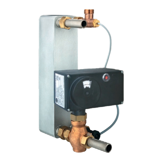
- Page 1 EB 5724 EN Translation of original instructions TROVIS 5724-3 (without fail-safe action) TROVIS 5725-3 (with fail-safe action) Electric Actuators with Process Controller for domestic hot water heating Firmware version 2.20 Edition August 2016...
- Page 2 Note on these mounting and operating instructions These mounting and operating instructions assist you in mounting and operating the device safely. The instructions are binding for handling SAMSON devices. The images shown in these instructions are for illustration purposes only. The actual product may vary.
-
Page 3: Table Of Contents
Contents Safety instructions and measures ..............1-1 Notes on possible severe personal injury ............1-4 Notes on possible personal injury ..............1-4 Notes on possible property damage .............1-5 Markings on the device ................2-1 Nameplate ....................2-1 Device code ....................2-2 Firmware versions ..................2-2 Design and principle of operation ...............3-1 Fail-safe action ...................3-2 Communication ..................3-3 Technical data ....................3-4... - Page 4 Emergency action ..................9-3 Servicing....................10-1 Decommissioning ..................11-1 Removal ....................12-1 12.1 Force-locking attachment ................12-1 12.2 Form-fit attachment ...................12-1 Repairs ....................13-1 13.1 Returning the actuator to SAMSON ............13-1 Disposal ....................14-1 Certificates ....................15-1 Annex......................16-1 16.1 Accessories ....................16-1 16.2 After-sales service ..................16-2 16.3 Configuration and parameter list ..............16-3 16.4 Customer-specific data ................16-5...
-
Page 5: Safety Instructions And Measures
Therefore, operators must ensure that the actuators are only used in operating conditions that meet the specifications used for sizing the actuator at the ordering stage. In case operators intend to use an actuator in other applications or conditions than specified, contact SAMSON. SAMSON does not assume any liability for damage resulting from the failure to use the de- vice for its intended purpose or for damage caused by external forces or any other external factors. Î Refer to the technical data for limits and fields of application as well as possible uses. See the 'Design and principle of operation' section. - Page 6 Î Observe the requirements for personal protective equipment specified in the valve docu- mentation. Î Check with the plant operator for details on further protective equipment. Revisions and other modifications Revisions, conversions or other modifications of the product are not authorized by SAMSON. They are performed at the user's own risk and may lead to safety hazards, for example. Fur- thermore, the product may no longer meet the requirements for its intended use. Safety features The limit switches switch off the motor in the end positions.
- Page 7 The following documents apply in addition to these mounting and operating instructions: − Configuration Manual for TROVIS 5724-3 and TROVIS 5725-3 Electric Actuators with Process Controller u KH 5724 − Mounting and operating instructions of the valve on which the electric actuator is mounted, e.g. for SAMSON valves: u EB 5861 for Type 3260 Three-way Valve u EB 5863 for Type 3226 Three-way Valve u EB 5866 for Type 3222 Globe Valve u EB 5867 for Type 3222 N Globe Valve u EB 5868 for Type 3213 and Type 3214 Globe Valves...
-
Page 8: Notes On Possible Severe Personal Injury
Safety instructions and measures 1.1 Notes on possible severe personal injury DANGER Risk of fatal injury due to electric shock. Î Before connecting wiring and performing any work on the device, disconnect the supply voltage and protect it against unintentional reconnection. Î Only use power interruption devices that can be protected against unintentional re- connection of the power supply. -
Page 9: Notes On Possible Property Damage
Safety instructions and measures WARNING Risk of personal injury through incorrect operation, use or installation as a result of information on the actuator being illegible. Over time, markings, labels and nameplates on the actuator may become covered with dirt or become illegible in some other way. As a result, hazards may go unnoticed and the necessary instructions not followed. There is a risk of personal injury. Î... - Page 10 NOTICE Malfunction due to a configuration that does not meet the requirements of the appli- cation. The electric actuator with process controller is configured for the specific application by setting configuration items and parameters. Î Perform the configuration for the specific application during start-up and after a re- set to default settings. Risk of damage to the screw heads on the front cover due to the use of the wrong tool.
-
Page 11: Markings On The Device
Markings on the device 2 Markings on the device 2.1 Nameplate SAMSON 0062 Controller with Electric Actuator Model Var.-ID Serial no. Firmware - Version: Type Year of manufacture Configuration ID Model designation (TROVIS 5725-3 only) Serial number DIN registration number (TROVIS 5725-3 only) Thrust Rated travel Transit time for rated travel... -
Page 12: Device Code
2.2 Device code Electric Actuator with Process Controller TROVIS 572 x - 3 Fail-safe action Without With Rated travel/adaptation 6 mm/force locking 12 mm/force locking 15 mm/form-fit Stem movement Standard Double stroking speed 2.3 Firmware versions Firmware revisions 2.11 2.13 Additional setting option 'Circulation pump (heating) reversed' in Function of switching output (F16) (see Annex and Configuration Manual u KH 5724). -
Page 13: Design And Principle Of Operation
They are particu- The output signal of the integrated digital larly suitable for mounting to SAMSON controller acts over the positioner on the syn- Types 3213, 3214, 3260, 3222 and 3226 chronous motor of the actuator. The force of Valves. the motor is transmitted to the actuator stem (3) via gear and crank disk. -
Page 14: Fail-Safe Action
Design and principle of operation ator stem extends, it presses on the plug stem Alternatively, the switching output can be (10) of the valve. used as fault alarm output or can be config- ured to register the tapping of hot water. The When the actuator stem retracts (force-lock- actuator is configured with the TROVIS-VIEW ing attachment), the plug stem follows the software. -
Page 15: Communication
Testing according to DIN EN 14597 The TROVIS 5725-3 Electric Actuator with Process Controller with fail-safe action "actuator stem extends" is tested by the German technical surveillance association TÜV according to DIN EN 14597 in combination with different SAMSON valves. The register number is available on request. 3.2 Communication Serial interface The actuator is fitted with an RS-232 serial interface. This allows communication with TROVIS-VIEW using SSP protocol. -
Page 16: Technical Data
Design and principle of operation 3.3 Technical data Electric actuator with TROVIS 5724 5725 process controller -310 -313 -320 -323 -330 -333 -310 -313 -320 -323 -330 -333 Fail-safe action Without Extends Rated travel Transit time for rated travel Transit time for fail-safe action –... - Page 17 Design and principle of operation Electric actuator with TROVIS 5724 5725 process controller -310 -313 -320 -323 -330 -333 -310 -313 -320 -323 -330 -333 Accessories Temperature sensor Pt 1000, fast response Water flow sensor 530 pulses/l, measuring range 1 to 30 l/min Flow switch Yes · Alternative to water flow sensor Manual override using 4 mm Allen key (after removing the front cover); actuator always returns to fail-safe position after release. For actuators tested according to DIN EN 14597: –15/+10 % The permissible medium temperature depends on the valve on which the electric actuator with process controller is mounted.
-
Page 18: Dimensions
Design and principle of operation 3.4 Dimensions TROVIS 5724-313/-323 TROVIS 5725-313/-323 TROVIS 5724-333 TROVIS 5725-333 TROVIS 5724-310/-320 TROVIS 5725-310/-320 Fig. 3-2: Dimensions in mm · TROVIS 5724-3 and 5725-3 Electric Actuators with Process Controller EB 5724 EN... - Page 19 Design and principle of operation TROVIS 5724-330 TROVIS 5725-330 Fig. 3-3: Dimensions in mm · TROVIS 5724-3 and 5725-3 Electric Actuators with Process Controller G ¾ G ¾ G ¾ Circulation pipe connection (in- Connecting piece (including Connecting piece (including cluding gasket) gasket) for valve G 1 gasket) for valve G ¾ Order no.
- Page 20 Design and principle of operation Ø5.4 Ø3.3 Type 5207-0060 Pt 1000 Sensor Water flow sensor with extension cable Time response: t < 1 s, Order no. 1400-9246 < 3 s; in water 0.4 m/s Measuring range 1 to 30 l/min, DN 10, PN 10, PN 16 IP 54 Max. medium temperature: 90 °C Max. medium temperature 70 °C Extension cable length: 2 m Sensor pocket (including gasket) for heat Sensor pocket (including gasket) for heat exchanger with G ¾...
-
Page 21: Shipment And On-Site Transport
1. Remove the packaging from the electric Î Observe the storage instructions. actuator. Î Avoid long storage times. Î Contact SAMSON in case of different 2. Check scope of delivery (see Fig. 4-1). storage conditions or longer storage 3. Dispose of the packaging in accordance times. - Page 22 Shipment and on-site transport Note We recommend regularly checking the elec- tric actuator with process controller and the prevailing storage conditions during long storage periods. Storage instructions − Protect the electric actuator against exter- nal influences (e.g. impact). − Protect the electric actuator against mois- ture and dirt.
-
Page 23: Installation
Installation 5 Installation Note The degree of protection IP 54 can only be 5.1 Installation conditions achieved up to device index .03 when the actuator is installed in the upright position. Work position See the last two figures of the configuration ID written on the nameplate for the device If not described otherwise in the valve docu- index. -
Page 24: Aligning The Travel Indication Scale
Installation 5.3 Aligning the travel indica- Î Remove scale, turn it and replace it so that the pin is positioned over the appro- tion scale priate hole (6, 12 or 15) corresponding The travel indication scale has two opposed to the rated travel (6, 1 or 15 mm travel). scales. -
Page 25: Trovis 5724-3 (Form-Fit Attachment)
Installation Force-locking attachment with coupling nut, Form-fit attachment with stem connector, e.g. e.g. to Type 3222 Valve with rod-type yoke on Series V2001 Valve Actuator stem Rod-type yoke Coupling nut Stem connector Handwheel (TROVIS 5724-3 only) Fig. 5-3: Attaching actuator and valve 1. Place the actuator on the yoke (4) and 5.4.2 TROVIS 5724-3 (form-fit fasten with the coupling nut (2). -
Page 26: Trovis 5725-3 (Force-Locking Attachment)
Installation 4. Position the clamps of the stem connector 4. Retract the actuator stem in manual level (5) included in the accessories on the in TROVIS-VIEW. Fasten valve and actu- ends of the actuator stem and plug stem ator together using the coupling nut. and screw tight. -
Page 27: Installing The Accessories
Installation 5.6 Installing the accessories Î Do not touch the wire ends of the switch- ing output L'. DHW tapping recognition Î Insulate the wire ends when the switching output is not used. Î Install the water flow sensor or flow switch into the pipeline (see associated documentation). - Page 28 Installation Supply voltage and switching output Pump 230 V, 50 Hz DANGER Live terminal L'! Î Do not touch. Version with fail-safe action only Temperature sensor and binary inputs Pt 1000 sensor BE 2 BE 1 BI1: Set point switchover BI2: Flow switch Current input for set point or measured value 0(4) ...
- Page 29 Installation Water flow sensor (WSS) TROVIS 5724-3 Extension cable TROVIS 5725-3 Signal 5 V 5 V Wire end ferrules PVC 3 x 0.5 mm² Connector Bushing GN WH Cable tie Nameplate 18.9 BN: Brown GN: Green Black WH: White Fig. 5-5: Connection of water flow sensor (WWS) EB 5724 EN...
- Page 30 EB 5724 EN...
-
Page 31: Operation
Operation 6 Operation 6.1 Device overview and operating controls Travel indicator Handwheel Set point potentiometer (underneath front housing cover) RJ12 port Red LED Yellow LED Fig. 6-1: Location of operating elements EB 5724 EN... -
Page 32: Indication With Leds
Operation 6.2 Indication with LEDs The electric actuator with process controller has a red and a yellow LED which indicate the operating state of the actuator. The LEDs are located underneath the cover on the printed circuit board (see Fig. 6-1). Î See the 'Operation' and 'Malfunctions' sections for the blinking pattern. -
Page 33: Start-Up And Configuration
Start-up and configuration 7 Start-up and configuration 7.2 Configuring the actuator The actuator is configured with the TROVIS- 7.1 Initializing the actuator VIEW software. In this case, the serial interface on the actuator is used to connect The actuator automatically performs a zero the actuator to the computer (see the 'Design calibration as soon as the supply voltage is and principle of operation' section). -
Page 34: Quick Check
Start-up and configuration 7.3 Quick check To test the electric actuator's ability to func- tion, the following quick checks can be per- formed: Î Apply the maximum and minimum con- trol signals (e.g. over the manual level in TROVIS-VIEW). Î Check the end positions of the valve. Î... -
Page 35: Operation
Operation 8 Operation The valve with electric actuator is ready for use when mounting and start-up have been com- pleted. NOTICE Operation disrupted by a blocked actuator or plug stem (form-fit version). Î Do not impede the movement of the actuator or plug stem by inserting objects into their path. - Page 36 Operation Blinking pattern of the yellow LED − Device OFF Time in s − Device ON Time in s Blinking pattern of the red LED − Device OFF or in normal operation Time in s − Device starting up Time in s − Zero calibration in progress Time in s − Transit time measurement in progress...
-
Page 37: Change Set Point At The Device
Operation Note NOTICE The blinking patterns for error indication are Risk of damage to the screw heads on the listed in the 'Malfunctions' section. front cover due to the use of the wrong tool. Î To screw or unscrew the screws, only use 8.3 Change set point at the de- TORX T10, TORX PLUS... -
Page 38: Manual Mode
Operation 8.4 Manual mode Direction of rotation − Turn clockwise: the actuator stem extends The actuator stem can be moved mechani- (see Fig. 8-1). cally or alternatively electrically in the manu- − Turn counterclockwise: the actuator stem al level in TROVIS-VIEW (u EB 6661). retracts (see Fig. 8-1). -
Page 39: Operation Using Memory Pen
Operation 8.5 Operation using memory Actuating shaft See u EB 6661. The memory pen can be loaded with data configured in TROVIS-VIEW and the config- uration data transferred to one or several devices of the same type and version. Additionally, the data from the device can be written to the memory pen. This allows the configuration data to be simply copied from one device and loaded onto other de- vices of the same type and version. - Page 40 Operation Blinking pattern of the yellow LED − Command mode Time in s − Memory pen action completed Time in s − Preparing to read from memory pen Time in s − Preparing to write data to memory pen Time in s − Preparing data logging Time in s − Data logging in progress...
-
Page 41: Copying Function
Operation Blinking pattern of the red LED − Memory pen inserted Time in s 1 Memory pen 2 Serial interface (RJ12 jack) Fig. 8-3: Connecting actuator and memory pen 8.5.1 Copying function Data transmission between the actuator and memory pen The memory pen can be used to copy setting The memory pen is connected to the actuator data to other TROVIS 5724-x Actuators after as shown in Fig. 8-3. Refer to the TROVIS-... -
Page 42: Command Mode
Operation 8.5.2 Command mode 8.6 Readings in TROVIS-VIEW In closed-loop operation, the actuator stem 8.6.1 Operating values can be moved to the top or bottom end posi- tion using the command pen regardless of the control conditions. Note Possible settings: The values in the 'Operating values' folder − No command cannot be changed. -
Page 43: Status Messages
Operation 8.6.4 Status messages In the 'Service' folder ('Status messages'), device and operation parameters are shown: Actuator Firmware version Serial number Device information Manufacturing parameters Operation Operating hours in h Operating hours at excess temperature in h Temperature inside device in °C Highest temperature inside device in °C Lowest temperature inside device in °C... -
Page 44: Statistics
Operation 8.6.5 Statistics In the 'Service folder' ('Statistics'), various readings of counters are shown: Device failures counters Supply voltage activated Program interruptions Limit contact error EEPROM error Alarms counters Signal failure at the temperature input Signal failure at the current input Flow rate exceeds measuring range Upper limit GWH exceeded Binary signals counters... -
Page 45: Malfunctions
Malfunctions 9 Malfunctions 9.1 Troubleshooting Î Troubleshooting (see Table 9-1). Note Contact our after-sales service for malfunctions not listed in the table. Table 9-1: Troubleshooting Error Possible reasons Recommended action Actuator or plug stem does not Actuator is blocked. Î Check attachment. move on demand. -
Page 46: Error Indication By Leds
Malfunctions 9.2 Error indication by LEDs Blinking pattern of the yellow LED − Plausibility error in memory pen Time in s − EEPROM error in memory pen Time in s Blinking pattern of the red LED − Temperature too high (upper limit (GWH) exceeded) Time in s − EEPROM error in device... -
Page 47: Emergency Action
Malfunctions − Flow rate at water flow sensor exceeds measuring range Time in s 9.3 Emergency action Plant operators are responsible for emergency action to be taken in the plant. Emergency action in the event of valve failure is described in the associated valve documen- tation. EB 5724 EN... - Page 48 EB 5724 EN...
-
Page 49: Servicing
Servicing 10 Servicing Note The electric actuator with process controller was checked by SAMSON before it left the factory. − The product warranty becomes void if service or repair work not described in these instructions is performed without prior agreement by SAMSON's After-sales Service. - Page 50 10-2 EB 5724 EN...
-
Page 51: Decommissioning
Decommissioning 11 Decommissioning To decommission the electric actuator for maintenance work or disassembly, proceed The work described in this section is only to as follows: be performed by personnel appropriately Î Put the control valve out of operation. qualified to carry out such tasks. See associated valve documentation. Î... - Page 52 11-2 EB 5724 EN...
-
Page 53: Removal
Removal 12 Removal Note The work described in this section is only to Hold the actuating shaft of actuators with be performed by personnel appropriately fail-safe action in place after retracting the qualified to carry out such tasks. actuator stem to prevent it from extending again. - Page 54 Force-locking attachment with coupling nut, Form-fit attachment with stem connector, e.g. e.g. to Type 3222 Valve with rod-type yoke on Series V2001 Valve Actuator stem Rod-type yoke Coupling nut Stem connector Handwheel (TROVIS 5724-3 only) Fig. 12-1: Attaching actuator and valve 12-2 EB 5724 EN...
-
Page 55: Repairs
Risk of actuator damage due to incorrect service or repair work. Î Do not perform any repair work on your own. Î Contact SAMSON's After-sales Service. 13.1 Returning the actuator to SAMSON Defective actuators can be returned to SAMSON for examination. - Page 56 13-2 EB 5724 EN...
-
Page 57: Disposal
Disposal 14 Disposal We are registered with the German national register for waste electric equipment (stiftung ear) as a producer of electrical and electronic equipment, WEEE reg. no.: DE 62194439 Î Observe local, national and internation- al refuse regulations. Î Do not dispose of components, lubricants and hazardous substances together with your other household waste. - Page 58 14-2 EB 5724 EN...
-
Page 59: Certificates
Certificates 15 Certificates The following certificates are included on the next pages: − EU declarations of conformity − TR CU certificate − Declaration of incorporation The certificates shown were up to date at the time of publishing. The latest certificates can be found on our website: u www.samsongroup.com > Products & Applications > Product selector > Actuators > 5724-3 u www.samsongroup.com > Products & Applications > Product selector > Actuators > 5725-3 EB 5724 EN 15-1... - Page 60 LVD 2014/35/EU EN 60730-1:2016, EN 61010-1:2010 RoHS 2011/65/EU EN 50581:2012 Hersteller / Manufacturer / Fabricant: SAMSON AKTIENGESELLSCHAFT Weismüllerstraße 3 D-60314 Frankfurt am Main Deutschland/Germany/Allemagne Frankfurt / Francfort, 2017-07-29 Im Namen des Herstellers/ On behalf of the Manufacturer/ Au nom du fabricant.
- Page 61 LVD 2014/35/EU EN 60730-1:2016, EN 61010-1:2010 RoHS 2011/65/EU EN 50581:2012 Hersteller / Manufacturer / Fabricant: SAMSON AKTIENGESELLSCHAFT Weismüllerstraße 3 D-60314 Frankfurt am Main Deutschland/Germany/Allemagne Frankfurt / Francfort, 2017-07-29 Im Namen des Herstellers/ On behalf of the Manufacturer/ Au nom du fabricant.
- Page 62 Certificates TR CU certificate 15-4 EB 5724 EN...
- Page 63 Certificates EB 5724 EN 15-5...
- Page 64 Certificates Declaration of incorporation 15-6 EB 5724 EN...
-
Page 65: Annex
Annex 16 Annex 16.1 Accessories Accessories Pt 1000 temperature sensor, fast response Type 5207-0060 Sensor pocket G ¾ Order no. 1400-9249 Sensor pocket G 1 Order no. 1400-9252 Connecting piece G ¾ Order no. 1400-9236 Connecting piece G 1 Order no. 1400-9237 Circulation pipe connection Order no. 1400-9232 Water flow sensor Order no. 1400-9246 Hardware package consisting of: Order no. 1400-9998 − Memory pen-64 − Connecting cable − Modular adapter Memory pen-64... -
Page 66: After-Sales Service
E-mail contact You can reach our after-sales service at u aftersalesservice@samsongroup.com. Addresses of SAMSON AG and its subsid- iaries The addresses of SAMSON, its subsidiaries, representatives and service facilities world- wide can be found on our website (u www.samsongroup.com) or in all... -
Page 67: Configuration And Parameter List
Annex 16.3 Configuration and parameter list Configuration list The function blocks F01 to F14 have the following listed functions. F = Function block WE = Default setting 0 = OFF, 1 = ON Function Meaning 01 DHW tapping recognition 0: Continuous control 1: Flow rate sensor active 02 Flow rate sensor 0: Flow switch... - Page 68 Annex Parameter list The parameters have the setting ranges as listed below. P = Parameter WE = Default setting Parameters Adjustment range Set point W1 60 °C 0 Up to 100 °C Set point W2 70 °C 0 Up to 100 °C Lower measuring range value Xmin 0 °C –50 Up to +90 °C Upper measuring range value Xmax 100 °C...
-
Page 69: Customer-Specific Data
Annex 16.4 Customer-specific data Station Operator SAMSON office Function blocks Parameters Setting Setting Adjustment range 60 °C 0 to 100 °C 70 °C 0 to 100 °C 0 °C –50 to +90 °C 100 °C 10 to 150 °C 95 °C 0 to 100 °C 5 °C 0 to 20 °C 0.1 to 50 25 s 0 to 999 s 0 s 0 to 999 s... - Page 70 16-6 EB 5724 EN...
- Page 72 EB 5724 EN SAMSON AKTIENGESELLSCHAFT Weismüllerstraße 3 · 60314 Frankfurt am Main, Germany Phone: +49 69 4009-0 · Fax: +49 69 4009-1507 samson@samsongroup.com · www.samsongroup.com...