Samson 5757-7 Mounting And Operating Instructions
Controller with electric actuator
Hide thumbs
Also See for 5757-7:
- Mounting and operating instructions (44 pages) ,
- Mounting and operating instructions (32 pages) ,
- Mounting and operating instructions (64 pages)
Table of Contents

Related Manuals for Samson 5757-7


Summary of Contents for Samson 5757-7
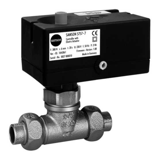
- Page 1 Controller with Electric Actuator Type 5757-7 for heating and cooling applications Fig. 1 · Type 5757-7 Controller with Electric Actuator Mounting and Operating Instructions EB 5757-7 EN Firmware version 2.00 Edition July 2009...
- Page 2 NOTICE indicates a property damage which, if not avoided, will result in death or message. serious injury. Note: Supplementary explanations, information and tips WARNING! WARNING indicates a hazardous situation which, if not avoided, could result in death or serious injury. EB 5757-7 EN...
-
Page 3: Table Of Contents
Installing TROVIS-VIEW software ....31 Starting TROVIS-VIEW and performing settings ... . 32 EB 5757-7 EN... - Page 4 Online operation (direct data transmission)....45 SAMSON memory pen ......46 8.2.1...
-
Page 5: General Safety Instructions
To avoid damage to any equipment, the following also applies: Proper shipping and appropriate storage are assumed. Note: Actuators with a CE marking fulfill the requirements of the Directives 2004/108/EC and 2006/95/EC. The Declaration of Conformity is available on request. EB 5757-7 EN... -
Page 6: Design And Principle Of Operation
When the actuator stem extends, the valve is closed, opposing the force of the valve The Type 5757-7 consists of a digital con- spring (7). When the actuator stem retracts, troller integrated into the housing of an elec- the valve is opened as the plug stem (6) fol- tric actuator. -
Page 7: Accessories
Communication, refer to section 7 be made over the TROVIS-VIEW software. Refer to section 7. TROVIS-VIEW Configuration and Opera- tor Interface for Type 5757-7 Controller The position of the slide switch determines with Electric Actuator which function and parameter settings (level Hardware package #1 or #2) is used for closed loop operation. -
Page 8: Technical Data
Technical data The LEDs are located underneath the cover Type 5757-7 Controller with Electric Actuator on top of the circuit board. Temperature sensor Max. 3 x Pt 1000 Blinking pattern of the yellow LED Measuring range –40 to 150 °C... - Page 9 • Data logging in progress: Time [s] • Exceptional error or sensor line break- age: Time [s] • EEPROM error in memory pen: Time [s] Time [s] • EEPROM error in device: Time [s] • Stem synchronization: Time [s] EB 5757-7 EN...
-
Page 10: Connection To The Valve
Time [s] • Return flow sensor defective: Time [s] • Potentiometer defective: Time [s] 2 Handwheel 3 Actuator stem 4 Coupling nut Fig. 4 · Mounting the actuator onto the valve EB 5757-7 EN... -
Page 11: Electrical Connection
Additionally, the controller with electric ac- tuator has a potentiometer input 1000 to 1100 Ω (e.g. Type 5257-7) or 1000 to 2000 Ω (e.g. Type 5257-2). This input is used to correct the room set point (± 5 K) in EB 5757-7 EN... - Page 12 Application with flow sensor, return flow sensor, outdoor sensor and potentiometer for adjusting the set point orange brown brown yellow black blue green black Fig. 5 · Wiring diagrams Note: Terminals at point of installation, not included in scope of delivery EB 5757-7 EN...
- Page 13 Application with flow sensor, return flow sensor and outdoor sensor as well as binary input (BI1) to switch between operating modes brown orange brown blue yellow black black green Fig. 6 · Wiring diagrams Note: Terminals at point of installation, not included in scope of delivery EB 5757-7 EN...
- Page 14 Application with flow sensor, return flow sensor and room sensor with mode selector switch and set point adjuster brown orange brown blue yellow black black green Fig. 7 · Wiring diagrams Note: Terminals at point of installation, not included in scope of delivery EB 5757-7 EN...
-
Page 15: Dimensions In Mm
Dimensions in mm Dimensions in mm Ø 12 2.5 m eL Stem retracts aL Stem extends Fig. 8 · Type 5757-7 Controller with Electric Actuator EB 5757-7 EN... - Page 16 Sensor, Pt 1000 Color: Cover and knobs RAL 9016 · Base RAL 7047 (flow and return flow temperature measurement) Continuous day mode (rated operation) Continuous night mode (reduced operation) Off/frost protection Fig. 9 · Accessories for heating applications EB 5757-7 EN...
-
Page 17: Functions
Return flow temperature limitation (see section 6.5) is an exception as it can reduce the flow temperature without restriction down to 20 °C flow temperature set point. ˚ Flow temperature Outdoor temperature ˚ Fig. 10 · Heating characteristics EB 5757-7 EN... - Page 18 RüS Return flow sensor District heating network return flow Flow sensor District heating network supply Fig. 11 · Typical application: Outdoor temperature compensated flow temperature control with return flow limitation; switching between operating modes over a binary contact (BI1) EB 5757-7 EN...
-
Page 19: Override Using Potentiometer
P17 – Outdoor temperature limit value at rated operation 22 °C 0 to 50 °C P18 – Outdoor temp. limit value at reduced operation 15 °C 0 to 50 °C P23 – Pump lag time 5 min 1 to 999 min EB 5757-7 EN... -
Page 20: Delayed Outdoor Temperature Adaptation
P01 – Flow temperature set point 70 °C 0 to 150 °C P02 – Flow temp. set-back in reduced operation 15 K 0 to 50 K Note: The return flow limitation and the potentiometer override are still active when config- ured correspondingly. EB 5757-7 EN... -
Page 21: Control With Reference Variable (Room Temperature)
The set point of the flow temperature is not affected when the P22 parameter ( Time interval flash adaptation) is set to 0. The heating deactivation remains active when the room temper- ature exceeds the value in Room temperature set point (P19/P20) plus Room temperature boost for switch-off (P21). EB 5757-7 EN... -
Page 22: Changing The Operating Modes
F08 - 0 Open binary input BI1 – Rated operation Binary input BI1: Closed binary input BI1 – OFF/Frost protection F08 - 1 Open binary input BI1 – Rated operation Closed binary input BI1 – Reduced operation EB 5757-7 EN... -
Page 23: Switchover Via Room Panel
The operating mode of the controller is determined at the mode selector switch on the Type 5257-7 Room Panel: Rated operation (day mode) Reduced operation (night mode) OFF/Frost protection Functions Configuration F05 – Potentiometer input F05 - 1 F06 – Resistance range of potentiometer F06 - 0 (Type 5257-7 Room Panel) EB 5757-7 EN... -
Page 24: Switchover Via Binary Input In Room Panel
The reduction amount is calculated from the deviation of the return flow temperature multi- plied by the factor Kp Return flow temperature limitation . The rate at which the return flow temperature is reduced by the calculated amount is determined by Tn Return flow tempera- ture limitation . EB 5757-7 EN... -
Page 25: Pump Forced Operation
Tn flow tem- perature control (P10) (the interval time increases as the Tn rises). The valve transit time Ty actuator transit time for valve travel (P11) reflects the time that the EB 5757-7 EN... -
Page 26: Direction Of Action
Port A -> AB closed, port B -> AB open (see Fig. 13) For three-way diverting valve: Port AB -> A open, port AB -> B closed Configuration Function F03 – Direction of stem action F03 - 0: Increasing/increasing F03 - 1: Increasing/decreasing EB 5757-7 EN... -
Page 27: Manual Operation
Mixing service Flow Return flow Fig. 13 · Type 3226 Three-way Mixing Valve mounted onto Type 5757-7 Controller with Electric Actuator 6.10 Manual operation 6.10.1 Handwheel The handwheel (red knob, see Fig. 2) is used to move the actuator stem when the power has been disconnected. -
Page 28: Function Block F13 For Manual Operation
“Specialist” user level (see section 7.4). You can switch the actuator to the manual level using the TROVIS-VIEW Configuration and Operator Interface if the manual level is enabled in online mode (Enable manual level pa- rameter = ON ( icon)). EB 5757-7 EN... - Page 29 (first enter the required value in Stem position in manual mode ) LED for operation Switching output The controller with electric actuator leaves the manual operation mode as soon as you exit the manual level or the online mode in TROVIS-VIEW. EB 5757-7 EN...
-
Page 30: Configuration And Operation Using Trovis-View Interface
Configuration and operation using TROVIS-VIEW interface General The TROVIS-VIEW software allows various smart SAMSON devices to be configured over a common operator interface. It consists of the operator interface, communication server, and the device-specific module. The software has a Windows ®... -
Page 31: Installing Trovis-View Software
2. Follow the on-screen prompts and instructions of the installation program. The TROVIS-VIEW Operator Interface can be used for different SAMSON devices. Note that the installation program also offers you the option of installing a demo module. To use the... -
Page 32: Starting Trovis-View And Performing Settings
You can read key information on this screen: Online/offline mode: The icon on the onlinebar is animated in online mode (see sec- tion 8.1.2). User level: The active user level (Customer or Specialist) is indicated on the status bar (see section 7.4). EB 5757-7 EN... - Page 33 5. If required, you can add a new or addi- tional TROVIS-VIEW module by selecting Add module in Options menu. A dialog box will appear, prompting you to enter the CD key, which you will find on the cover of the original CD-ROM. EB 5757-7 EN...
-
Page 34: Changing The User Level
Note: The user level can only be changed in offline mode. 1. Select User Level in Device menu. 2. Select “Specialist” from drop-down list. 3. Enter password. This password is “samson“ in the delivered state. Click Modify Password button to open the window where you can change the password. -
Page 35: Activating/Deactivating Functions
Downloads status of the function block to device. Displayed only in offline mode (see section 8.1.1) [Default: ...] Resets function block to default setting (setting in gray to indicate that the status of function block is the same as the default setting) EB 5757-7 EN... -
Page 36: Setting Parameters
[Write] Downloads parameter value to device. Displayed only in offline mode (see section 8.1.1) [Default: ...] Resets parameter to default setting (setting in gray to indicate that the parameter value is the same as the default setting) EB 5757-7 EN... -
Page 37: Reading Operation Data
Operation and Diagnostics as well as in the subdirectories Test functions, Calibration and Status messages . Change the user level to “Specialist” by selecting User Level in Device menu (see section 7.4). EB 5757-7 EN... -
Page 38: Diagnostics
Configuration and operation using TROVIS-VIEW interface Diagnostics The Diagnostics folder contains Information and Error . Information Error Note: In the user level “Specialist”, the EEPROM error , Motor data and Elapsed hours meter are displayed. EB 5757-7 EN... -
Page 39: Additional Diagnostics Folders In Specialist User Level
Configuration and operation using TROVIS-VIEW interface 7.7.1 Additional diagnostics folders in Specialist user level Test functions Manual level See section 6.10.4 for more details. Calibration EB 5757-7 EN... - Page 40 Configuration and operation using TROVIS-VIEW interface Status messages EB 5757-7 EN...
-
Page 41: Operational Data Graph (Trend Viewer)
[a] in the View menu (section 7.3). In online mode, all data of the active folder are cyclically uploaded from the controller with electric actuator. These data can be viewed in the Operation folder. EB 5757-7 EN... - Page 42 .”log” affix as well as when exiting the online mode. This file can be edited as required. Detailed information is contained in the online help. EB 5757-7 EN...
-
Page 43: Data Transmission
Memory pen – 64 the actuator. order no. 1400-9753 Data can be transferred to the serial interface over the SAMSON connecting ca- ble or over a memory pen together with a modular adapter. A memory pen allows you to simply copy and download configuration data onto other devices. -
Page 44: Data Transmission Between Trovis-View And The Actuator (Connecting Cable)
4 and the device is ready for operation. Data transmission between TROVIS-VIEW and the actuator (connecting cable) 1. Connect the serial port of the computer using the SAMSON connecting cable to the serial interface connection of the ac- tuator. 2. Select Communications in Options menu to open the server settings window. -
Page 45: Offline Operation (Indirect Data Transmission)
Deactivate online operation: Select Online in Device menu while the online mode is activated. The online mode is canceled. Note: Alternatively, click in the device toolbar to activate online operation and click activate online operation. EB 5757-7 EN... -
Page 46: Samson Memory Pen
Data transmission SAMSON memory pen The SAMSON memory pen serves as a data carrier and is able to load and store data in its non-volatile memory. The memory pen can be loaded with data configured in TROVIS-VIEW and the settings transferred to one or several controllers with electric actuators of the same type and version. -
Page 47: Data Transmission Between Actuator And Memory Pen
1. Plug memory pen (3) together with modular adapter (2) into the serial interface (COM port) of the PC (Fig. 15). 3 Memory pen 4 Serial interface (RJ 12 jack) Fig. 16 · Connecting actuator – memory pen EB 5757-7 EN... -
Page 48: Copy Function
Remove the memory pen from the actua- tor. 8.2.3 Copy function The memory pen can be used to copy setting data to other Type 5757-7 Actuators as soon as the data from the actuator have been transferred to the memory pen. EB 5757-7 EN... -
Page 49: Command Mode
Note: The data logging function can only be performed with the memory pen – 64. The memory pen – 64 allows the following data to be saved: – Flow temperature – Return flow temperature – Binary input state EB 5757-7 EN... - Page 50 Note: You can load a data logging file in the Trend Viewer by selecting Load a graph from the context-sensitive menu. Transfer data onto a computer 1. Plug the memory pen (3) together with the modular adapter (2) into the serial interface (COM port) of the computer (1) (Fig. 15). EB 5757-7 EN...
-
Page 51: Functional Test Assistant
Data transmission 2. Select Upload logged data in Memory pen menu. 3. Choose target directory. If the target directory is not changed, data will be saved in SAMSON folder [Type 5757-7]. 4. Enter a file name. 5. Click Save button to start data transmission. -
Page 52: Appendix
1 – Gradient shift → Section 6.1.1 and F05 - 1) 0 – BI short-circuited: OFF w. frost protection → Section 6.3.1 08 Function of binary input (only effective with F05 - 0) 1 – BI short-circuited: Reduced operation → Section 6.3.1 EB 5757-7 EN... -
Page 53: Parameter List
Minimum flow temperature 20 °C 0 to 150 °C Maximum flow temperature 120 °C 0 to 150 °C Heating characteristic gradient 0.2 to 3.2 Heating characteristic level –30 to 30 K Gradient shift range via potentiometer 0.0 to 1.5 EB 5757-7 EN... -
Page 54: Resistance Values With Pt 1000 Resistors
1000.0 1019.5 1039.0 °C Ω 1058.5 1077.9 1097.3 1116.7 1136.1 1155.4 1174.7 1194.0 1213.2 1232.4 °C Ω 1251.6 1270.7 1289.8 1308.9 1328.0 1347.0 1366.0 1385.0 1403.9 1422.9 °C Ω 1441.7 1460.6 1479.4 1498.2 1517.0 1535.8 1554.5 1573.1 EB 5757-7 EN... -
Page 55: Customer Settings
0 to 50 °C 15 °C 0 to 50 °C 20 °C 10 to 40 °C 15 °C 10 to 40 °C 1 to 6 K 10 min 0 to 100 min 5 min 1 to 999 min EB 5757-7 EN... - Page 56 EB 5757-7 EN...
-
Page 57: Index
Online mode ....43, 45 Initialization ..... 12 EB 5757-7 EN... - Page 58 Plug stem ......6 Trend Viewer ....41 - 42 EB 5757-7 EN...
- Page 59 Valve spring ..... . 6 Wire breakage ....11 EB 5757-7 EN...
- Page 60 SAMSON AG · MESS- UND REGELTECHNIK Weismüllerstraße 3 · 60314 Frankfurt · Germany Phone: +49 69 4009-0 · Fax: +49 69 4009-1507 EB 5757-7 EN Internet: http://www.samson.de...