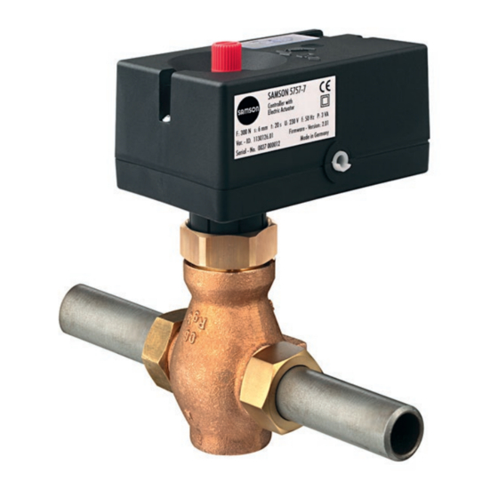
Samson TROVIS 5757-7 Mounting And Operating Instructions
Electric actuator with process controller for heating and cooling applications
Hide thumbs
Also See for TROVIS 5757-7:
- Mounting and operating instructions (44 pages) ,
- Mounting and operating instructions (32 pages) ,
- Mounting and operating instructions (60 pages)

Related Manuals for Samson TROVIS 5757-7


Summary of Contents for Samson TROVIS 5757-7
- Page 1 EB 5757-7 EN Translation of original instructions TROVIS 5757-7 Electric Actuator with Process Controller For heating and cooling applications Firmware version 2.04 Edition January 2020...
- Page 2 Note on these mounting and operating instructions These mounting and operating instructions assist you in mounting and operating the device safely. The instructions are binding for handling SAMSON devices. The images shown in these instructions are for illustration purposes only. The actual product may vary.
-
Page 3: Table Of Contents
Contents Safety instructions and measures ..............1-1 Notes on possible severe personal injury ............1-4 Notes on possible personal injury ..............1-4 Notes on possible property damage .............1-5 Markings on the device ................2-1 Nameplate ....................2-1 Firmware versions ..................2-1 Design and principle of operation ...............3-1 Communication ..................3-2 Technical data ....................3-3 Dimensions ....................3-4... - Page 4 Troubleshooting ..................9-1 Error priority ....................9-2 Error indication by LEDs ................9-2 Emergency action ..................9-4 Servicing....................10-1 Decommissioning ..................11-1 Removal ....................12-1 Repairs ....................13-1 13.1 Returning the actuator to SAMSON ............13-1 Disposal ....................14-1 Certificates ....................15-1 Annex......................16-1 16.1 Accessories ....................16-1 16.2 After-sales service ..................16-2 16.3 Configuration list and customer-specific data ..........16-3...
-
Page 5: Safety Instructions And Measures
Therefore, operators must ensure that the actuator is only used in operating conditions that meet the specifications used for sizing the actuator at the ordering stage. In case operators intend to use the actuator in other applications or conditions than specified, contact SAMSON. SAMSON does not assume any liability for damage resulting from the failure to use the de- vice for its intended purpose or for damage caused by external forces or any other external factors. Î Refer to the technical data for limits and fields of application as well as possible uses. See the 'Design and principle of operation' section. - Page 6 Î Check with the plant operator for details on further protective equipment. Revisions and other modifications Revisions, conversions or other modifications of the product are not authorized by SAMSON. They are performed at the user's own risk and may lead to safety hazards, for example. Fur- thermore, the product may no longer meet the requirements for its intended use.
- Page 7 The following documents apply in addition to these mounting and operating instructions: − Configuration Manual u KH 5757-7 for TROVIS 5757-7 Electric Actuator with Process Controller (detailed description of all functions and parameters) − Mounting and operating instructions of the valve on which the electric actuator is mount- ed, e.g. for SAMSON valves: u EB 3135-1 for Type 2488 Pressure-independent Control Valve (PICV) u EB 3136 for Type 2488 N Pressure-independent Control Valve (PICV) u EB 5861 for Type 3260 Three-way Valve u EB 5863 for Type 3226 Three-way Valve...
-
Page 8: Notes On Possible Severe Personal Injury
Safety instructions and measures 1.1 Notes on possible severe personal injury DANGER Risk of fatal injury due to electric shock. Î Before connecting wiring and performing any work on the device, disconnect the supply voltage and protect it against unintentional reconnection. Î Only use power interruption devices that can be protected against unintentional re- connection of the power supply. -
Page 9: Notes On Possible Property Damage
Safety instructions and measures 1.3 Notes on possible property damage NOTICE Risk of actuator damage due to the supply voltage exceeding the permissible toler- ances. The actuator is designed for use according to regulations for low-voltage installations. Î Observe the permissible tolerances of the supply voltage. Risk of actuator damage due to excessively high tightening torques. - Page 10 EB 5757-7 EN...
-
Page 11: Markings On The Device
Markings on the device 2 Markings on the device 2.1 Nameplate TROVIS 5757-7 Electric Actuator with Process Controller Var.-ID xxxxxxx Serial no. xxxx *xxxxxx* F: 300 N s: 6 mm v: 0.3 mm/s Firmware: 2.xx U: 230 V f: 50 Hz... - Page 12 EB 5757-7 EN...
-
Page 13: Design And Principle Of Operation
(1000 to of heating systems in small to medium-sized 1100 Ω or 1000 to 2000 Ω) to measure buildings. It is particularly suitable for the flow temperature. This input influences mounting to SAMSON Types 3222, the heating characteristic in the case of out- 3222 N, 2488 and 3267 Valves (DN 15 to door-temperature-controlled control and the 25) as well as to special versions of room temperature set point is corrected in Type 3226 and Type 3260 Valves. -
Page 14: Communication
Design and principle of operation 3.1 Communication retracted Actuator stem extended Serial interface The actuator is fitted with an RS-232 serial interface. This allows communication with TROVIS-VIEW using SSP protocol. Configuration The actuator is configured using the TROVIS- VIEW software that enables the user to easily configure the controller as well as view process parameters online. Note TROVIS-VIEW can be downloaded free of charge from our website at u www.samsongroup.com >... -
Page 15: Technical Data
Design and principle of operation 3.2 Technical data TROVIS 5757-7 Connection to valve Force-locking Rated travel 6 mm Transit time for rated travel 20 s Thrust 300 N Supply voltage 230 V (±10 %)/50 Hz Power consumption 5 VA Temperature sensor max. 3x Pt 1000 Operating temperature range –40 to +150 °C Binary inputs (instead of the 1) Floating contact, contact load 5 V/1 mA potentiometer) -
Page 16: Dimensions
Design and principle of operation 3.3 Dimensions Ø 12 2.5 m eL Stem retracts aL Stem extends Fig. 3-2: Dimensions in mm · TROVIS 5757-7 EB 5757-7 EN... - Page 17 Design and principle of operation Type 5227-4 Outdoor Sensor Type 5257-7 Room Panel Type 5267-2 Contact Sensor Fig. 3-3: Dimensions in mm · Accessories for heating applications EB 5757-7 EN...
-
Page 18: Values For Resistance Thermometers
Design and principle of operation 3.4 Values for resistance thermometers Pt 1000 sensors °C –35 –30 –25 –20 –15 –10 –5 Ω 862.5 882.2 901.9 921.6 941.2 960.9 980.4 1000.0 1019.5 1039.0 °C Ω 1058.5 1077.9 1097.3 1116.7 1136.1 1155.4 1174.7 1194.0 1213.2 1232.4 °C +100 +105... -
Page 19: Shipment And On-Site Transport
4.2 Removing the packaging improper storage. from the actuator Î Observe the storage instructions. Î Avoid long storage times. Î Contact SAMSON in case of different Note storage conditions or longer storage Do not remove the packaging until immedi- times. - Page 20 Shipment and on-site transport Storage instructions − Protect the electric actuator against exter- nal influences (e.g. impact). − Protect the electric actuator against mois- ture and dirt. − Make sure that the ambient air is free of acids or other corrosive media. − Observe the permissible storage tem- perature from –20 to +70 °C.
-
Page 21: Installation
Installation 5 Installation 5.2 Preparation for installation Before installation, make sure the following 5.1 Installation conditions conditions are met: − The actuator is not damaged. Work position Proceed as follows: If not described otherwise in the valve docu- mentation, the work position for the control Lay out the necessary material and tools to valve is the front view looking onto the oper- have them ready during mounting. -
Page 22: Installing The Control Valve Into The Pipeline
Installation 1. Turn the manual adjuster counterclock- − Mount the return flow sensor (e.g. wise and move the actuator stem to the Type 5267-2 Contact Sensor) to a pipe. top end position. Î See u T 5220. NOTICE 5.6 Electrical connection Risk of damage to the actuator by turning it too far. NOTICE Î... - Page 23 Installation NOTICE Risk of actuator damage due to incorrect wiring of the inputs. Î Wire the inputs range according to the technical data (see the 'Design and prin- ciple of operation' section). Wiring Î Connect the wiring as shown in Fig. 5-3, Fig. 5-4 or Fig. 5-5. Î Insulate any wires that are not used. EB 5757-7 EN...
- Page 24 Installation RüS 230 V, 50 Hz L´ DANGER Live wires Î Do not touch the wires. Operation with flow sensor (VS), return flow sensor (RüS) and outdoor sensor (AS) and potentiometer functioning as set point adjuster 230 V, 50 Hz L´ DANGER Live wires Î Do not touch the wires. Operation with flow sensor (VS), outdoor sensor (AS), binary input (BI2) to switch between operating mode and potentiometer for adjusting the set point OG = Orange YE = Yellow RD = Red...
- Page 25 Installation RüS 230 V, 50 Hz L´ DANGER Live wires Î Do not touch the wires. Operation with flow sensor (VS), return flow sensor (RüS), outdoor sensor (AS) and binary input (BI1) to switch between operating modes RüS 230 V, 50 Hz L´ DANGER Live wires Î Do not touch the wires. Operation with flow sensor (VS) and outdoor sensor (AS) OG = Orange YE = Yellow RD = Red BN= Brown BK = Black...
- Page 26 Installation Type 5257-7 Room RüS Panel 230 V, 50 Hz L´ DANGER Live wires Î Do not touch the wires. OG = Orange YE = Yellow RD = Red BN= Brown BK = Black GN = Green BU = Blue Operation with flow sensor (VS), return flow sensor (RüS) and room sensor with mode selector switch and set point adjuster Fig. 5-5: Electrical connection (part 3) Note The terminals are not included in the scope of delivery.
-
Page 27: Operation
Operation 6 Operation 6.1 Device overview and operating controls Manual adjuster Serial interface Slider switch (red) Travel indicator Cover/LEDs Manual adjuster Fig. 6-1: Location of operating elements 6.2 Indication with LEDs 6.3 Slider switch The electric actuator with process controller The slider switch is used to switch between has a red and a yellow LED which indicate two different control configurations and the operating state of the actuator. -
Page 28: Serial Interface
Operation 6.4 Serial interface The serial interface (RJ12 jack) is used for communication with the actuator. Push the cover to access it (see Fig. 6-1). 6.5 Control mode switchover with a room panel The Type 5257-7 Room Panel can be used to select an operating mode (day mode, night mode or frost protection). The room tempera- ture set point can also be changed. -
Page 29: Start-Up And Configuration
Start-up and configuration 7 Start-up and configuration 7.2 Configuring the actuator The actuator is configured with the TROVIS- 7.1 Initializing the actuator VIEW software. In this case, the serial interface on the actuator is used to connect The initialization process starts automatically the actuator to the computer (see the 'Design after the actuator has been connected to the and principle of operation' section). - Page 30 EB 5757-7 EN...
-
Page 31: Operation
Operation 8 Operation The valve with electric actuator is ready for use when mounting and start-up have been com- pleted. 8.1 Closed-loop control The electric actuator with process controller normally operates in closed-loop operation. In this case, the control behavior and movement of the actuator stem depend on the parameter settings (see Configuration Manual u KH 5757-7). - Page 32 Operation − Device ON Time in s − Return flow temperature limitation active Time in s Blinking pattern of the red LED − Device OFF or in normal operation Time in s − Device starting up Time in s − Zero calibration in progress Time in s − Transit time measurement in progress Time in s...
-
Page 33: Manual Mode
Operation 8.3 Manual mode Î Turn counterclockwise The actuator stem retracts (approx. four turns Manual adjuster for 1 mm travel). Travel and direction of action can be read off the travel indicator on the side of the ac- tuator housing (see Fig. 8-1). 8.4 Operation using memory Î... - Page 34 Operation Blinking pattern of the yellow LED − Command mode Time in s − Memory pen action completed Time in s − Preparing to read from memory pen Time in s − Preparing to write data to memory pen Time in s − Preparing data logging Time in s − Data logging in progress...
-
Page 35: Copying Function
Operation Blinking pattern of the red LED − Command mode Time in s 8.4.1 Copying function Data transmission between the actuator and memory pen The memory pen can be used to copy setting The memory pen is connected to the actuator data to other TROVIS 5757-7 Actuators after as shown in Fig. 8-2. Refer to the TROVIS- the data from the actuator have been trans-... -
Page 36: Readings In Trovis-View
Operation 8.5 Readings in TROVIS-VIEW 8.5.1 Operating values In online mode, the current operating values are listed in the 'Operating values' folder. De- pending on the basic setting, a graph is shown under the 'Operating values' window. Note The values in the 'Operating values' folder cannot be changed. 8.5.2 Operating states Error messages can be read in the 'Service' folder ('Operating states'). -
Page 37: Status Messages
Operation 8.5.4 Status messages In the 'Service' folder ('Status messages'), device and operation parameters are shown: Actuator Firmware version Serial number Device information Manufacturing parameters Operation Operating hours in h Operating hours at excess temperature in h Temperature inside device in °C 8.5.5 Statistics In the 'Service folder' ('Statistics'), various readings of counters are shown: Device failures counters... - Page 38 EB 5757-7 EN...
-
Page 39: Malfunctions
Malfunctions 9 Malfunctions 9.1 Troubleshooting Î Troubleshooting (see Table 9-1). Note Contact SAMSON's After-sales Service for malfunctions not listed in the table. Table 9-1: Troubleshooting Error Possible reasons Recommended action Actuator or plug stem does not Actuator is blocked. Î Check attachment. -
Page 40: Error Priority
Malfunctions 9.2 Error priority The connected sensors are monitored for line breakages. A fault in the line of a sensor is in- dicated by the red LED blinking. Each sensor has its own blinking pattern (see section 9.3). In the event that several sensors are defective, the LED blinks using the sequence for the sensor with the highest priority. - Page 41 Malfunctions Blinking pattern of the red LED − Limit contact error Time in s − Exceptional error or sensor line breakage Time in s − EEPROM error in device Time in s − Flow sensor defective Time in s − Outdoor sensor/room sensor defective Time in s − Return flow sensor defective Time in s...
-
Page 42: Emergency Action
Malfunctions 9.4 Emergency action Plant operators are responsible for emergency action to be taken in the plant. Emergency action in the event of valve failure is described in the associated valve documen- tation. EB 5757-7 EN... -
Page 43: Servicing
Servicing 10 Servicing Note The electric actuator with process controller was checked by SAMSON before it left the factory. − The product warranty becomes void if service or repair work not described in these instructions is performed without prior agreement by SAMSON's After-sales Service. - Page 44 10-2 EB 5757-7 EN...
-
Page 45: Decommissioning
Decommissioning 11 Decommissioning To decommission the electric actuator for maintenance work or disassembly, proceed The work described in this section is only to as follows: be performed by personnel appropriately Î Put the control valve out of operation. qualified to carry out such tasks. See associated valve documentation. Î... - Page 46 11-2 EB 5757-7 EN...
-
Page 47: Removal
Removal 12 Removal The work described in this section is only to be performed by personnel appropriately qualified to carry out such tasks. DANGER Risk of fatal injury due to electric shock. Î Before disconnecting the wires at the actuator, switch off the supply voltage and protect it against unintentional reconnection. - Page 48 12-2 EB 5757-7 EN...
-
Page 49: Repairs
Risk of actuator damage due to incorrect service or repair work. Î Do not perform any repair work on your own. Î Contact SAMSON's After-sales Service. 13.1 Returning the actuator to SAMSON Defective actuators can be returned to SAMSON for examination. - Page 50 13-2 EB 5757-7 EN...
-
Page 51: Disposal
Disposal 14 Disposal We are registered with the German national register for waste electric equipment (stiftung ear) as a producer of electrical and electronic equipment, WEEE reg. no.: DE 62194439 Î Observe local, national and internation- al refuse regulations. Î Do not dispose of components, lubricants and hazardous substances together with your other household waste. - Page 52 14-2 EB 5757-7 EN...
-
Page 53: Certificates
Certificates 15 Certificates The following certificate is shown on the next page: − EU declaration of conformity The certificate shown was up to date at the time of publishing. The latest certificates can be found on our website at: u www.samsongroup.com > Products & Applications > Product selector > Actuators > 5757-7 EB 5757-7 EN 15-1... - Page 54 LVD 2014/35/EU EN 60730-1:2016, EN 61010-1:2010 RoHS 2011/65/EU EN 50581:2012 Hersteller / Manufacturer / Fabricant: SAMSON AKTIENGESELLSCHAFT Weismüllerstraße 3 D-60314 Frankfurt am Main Deutschland/Germany/Allemagne Frankfurt / Francfort, 2017-07-29 Im Namen des Herstellers/ On behalf of the Manufacturer/ Au nom du fabricant.
-
Page 55: Annex
Annex 16 Annex 16.1 Accessories Accessories Contact sensor Type 5267-2 Outdoor sensor Type 5227-4 Room panel Type 5257-7 Hardware package consisting of: Order no. 1400-9998 − Memory pen-64 − Connecting cable − Modular adapter Memory pen-64 Order no. 1400-9753 Connecting cable Order no. 1400-7699 Modular adapter Order no. -
Page 56: After-Sales Service
E-mail contact You can reach our after-sales service at u aftersalesservice@samsongroup.com. Addresses of SAMSON AG and its subsid- iaries The addresses of SAMSON, its subsidiaries, representatives and service facilities world- wide can be found on our website (u www.samsongroup.com) or in all SAMSON product catalogs. Required specifications Please submit the following details: − Model number... -
Page 57: Configuration List And Customer-Specific Data
Annex 16.3 Configuration list and customer-specific data Function block list There are separate two levels #1 and #2. Both levels contain the functions F01 to F13 with the specified default settings and meanings. The functions F01 to F13 have the following listed functions. F = Function block 0 = OFF, 1 = ON Function Default Meaning 01 Control mode 0 – Fixed set point control 1 –... - Page 58 Annex Parameter list There are separate two parameter levels #1 and #2. Both parameter levels contain the functions P01 to P23 with the specified default settings and setting ranges. The parameters have the setting ranges as listed below. Parameter Default Adjustment range Flow temperature set point 70 °C 0 to 150 °C Flow temperature set-back in reduced operation 15 K 0 to 50 K Min. flow temperature 20 °C 0 to 150 °C Max. flow temperature 120 °C 0 to 150 °C Heating characteristic gradient 0.2 to 3.2 Heating characteristic level 0 K –30 to +30 K...
- Page 59 Annex Customer-specific data Station Operator SAMSON office Function blocks Parameters Setting Setting Default Default Adjustment range 70 °C 0 to 150 °C 15 K 0 to 50 K 20 °C 0 to 150 °C 120 °C 0 to 150 °C 0.2 to 3.2 0 K –30 to +30 K 0.0 to 1.5 15 K 0 to 30 K 0.1 to 50.0 120 s 0 to 999 s 24 s...
- Page 60 Annex Parameters Setting Default Adjustment range 2 K 1 to 6 K 10 min 0 to 100 min 5 min 1 to 999 min 16-6 EB 5757-7 EN...
- Page 64 EB 5757-7 EN SAMSON AKTIENGESELLSCHAFT Weismüllerstraße 3 · 60314 Frankfurt am Main, Germany Phone: +49 69 4009-0 · Fax: +49 69 4009-1507 samson@samsongroup.com · www.samsongroup.com...