GE Advantium 240 Technical Service Manual
Hide thumbs
Also See for Advantium 240:
- Installation manual (33 pages) ,
- Installation manual (34 pages)
Table of Contents
Advertisement
https://appliancetechmanuals.com
GE Consumer & Industrial
Technical Service Guide
JULY 2008
Advantium 240
PSB2200NWW
PSB2200NBB
PSB2201NSS
ZSC2200NWW
ZSC2200NBB
ZSC2201NSS
ZSC2202NSS
31-9173
GE Appliances
General Electric Company
Louisville, Kentucky 40225
O
M
VEN
ICROWAVE
C
ONV
S
PEED
F
AVORITE
B
AKE
C
OOK
E
XPRESS
C
R
OOK
ECIPES
B
ROIL
C
W
USTOM
ARM
D
R
T
EFROST
EHEAT
IMER
S
C
P
PEED
OOK
ROOF
O
VEN
L
IGHT
– 1 –
S
TART
B
H
ACK
ELP
P
AUSE
C
LEAR
P
OWER
O
PIONS
O
T
FF
EMP
OVEN DEMO LOCKED TURN DIAL REM MUTE TIMER
L
U
OCK/
NLOCK
H
S
OLD 5
ECONDS
Advertisement
Table of Contents

Related Manuals for GE Advantium 240


Summary of Contents for GE Advantium 240
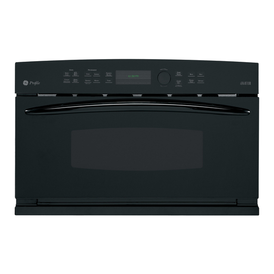
- Page 1 GE Consumer & Industrial Technical Service Guide JULY 2008 Advantium 240 ICROWAVE PEED AVORITE TART XPRESS ECIPES ROIL AUSE LEAR OWER USTOM PIONS PSB2200NWW EFROST EHEAT IMER PEED ROOF OVEN DEMO LOCKED TURN DIAL REM MUTE TIMER IGHT OCK/...
- Page 2 If grounding wires, screws, straps, clips, nuts, or washers used to complete a path to ground are removed for service, they must be returned to their original position and properly fastened. GE Consumer & Industrial Technical Service Guide Copyright © 2008 All rights reserved.
- Page 3 https://appliancetechmanuals.com PRECAUTIONS TO BE OBSERVED BEFORE AND DURING SERVICING TO AVOID POSSIBLE EXPOSURE TO EXCESSIVE MICROWAVE ENERGY. A. DO NOT OPERATE OR ALLOW THE OVEN TO BE OPERATED WITH THE DOOR OPEN. B. IF THE OVEN OPERATES WITH THE DOOR OPEN, INSTRUCT THE USER NOT TO OPERATE THE OVEN AND CONTACT THE MANUFACTURER IMMEDIATELY.
-
Page 4: Table Of Contents
https://appliancetechmanuals.com Table of Contents Capacitor and Diode ...............................33 Cavity Light ..................................30 Circulation Blower Assembly ............................36 Component Access Chart ............................23 Component Locator Views ............................17 Components ..................................23 Control Boards and Panel Connections .........................20 Control Features ................................8 Control Panel Assembly ..............................26 Convection Heater Assembly and Thermistor ....................41 Damper Assembly ................................35 Demo Mode ..................................15 Diagnostics and Service Information ........................47... -
Page 5: Nomenclature
Nomenclature Model Number P S B 2 2 0 0 N B B Brand P = GE Profi le Z = Monogram Product Color BB = Black GE Speedcook Technology SS = Stainless Steel WW = White fi guration... -
Page 6: Introduction
https://appliancetechmanuals.com Introduction The new Advantium oven uses breakthrough Speedcook technology to harness the power of light. The Advantium oven cooks the outside of foods much like conventional radiant heat, while also penetrating the surface so the inside cooks simultaneously. While halogen light is the primary source of power, a convection system and ceramic heater assist in the cooking, with a "microwave boost”... - Page 7 https://appliancetechmanuals.com Turntable Window The turntable must always be in Allows cooking to be viewed while place, on the oven floor, for all keeping microwaves confined in cooking. Be sure the turntable is the oven. seated securely over the spindle Door Handle in the center of the oven with the Pull to open the door.
-
Page 8: Control Features
https://appliancetechmanuals.com Control Features With your Advantium oven, you can cook with high-intensity halogen lights, ceramic heaters, convection heating element, and/or conventional microwave energy. SPEEDCOOK/Repeat Last TIMER Press this pad to access the pre-set Press this pad to set the minute timer. speedcook menu. - Page 9 https://appliancetechmanuals.com Cooking Times Oven Heat When Speedcooking preprogrammed foods, you No preheating time is required during Speedcook may see in the display cycles. The oven begins cooking immediately. OPTIMIZING COOK TIME several seconds after you press . The START/ PAUSE The door and inside of the oven will be very hot.
-
Page 10: Speed Cook System
https://appliancetechmanuals.com Speed Cook System Halogen Lamp and Ceramic Heaters • Two 1200-watt halogen bulbs cook food from above. • One 500-watt ceramic heater cooks food from below. Rear Convection Heat Element • A 1500-watt convection element operates when using convection bake. •... - Page 11 Speedcook. use the glass tray. UPPER POWER (U) controls the upper halogen The Advantium 240 provides 950 watts of heaters. Select a higher setting for such foods as microwave power, which is delivered directly pizza and baked goods. Select a lower setting for into the oven cavity to work independently, or in foods, such as casseroles, meats, and fi...
- Page 12 https://appliancetechmanuals.com LOWER POWER (L) controls the lower ceramic heater. The programming on the smart board which Select a higher setting for thick or dense foods that controls the upper halogen lamps (pair) and the may not cook quickly in the center. Select a lower lower ceramic heater, as well as the high voltage/ setting for thin foods, such as cookies.
- Page 13 https://appliancetechmanuals.com Voltage Compensation Voltage compensation only occurs when Note: using a preselected menu item in Speedcook. These SMART BOARD items require compensation for accurate and consistent cooking results. Voltage fl uctuations in the power supply can cause inconsistencies in cooking. The main PCB measures line voltage at the start of each Speedcooking selection and adjusts the cooking time to achieve consistent results.
-
Page 14: Proof Feature
https://appliancetechmanuals.com Thermal Compensation Proof Feature Thermal compensation only occurs once and Note: The purpose of the PROOF feature is to help dough only when using a preprogrammed menu item in rise at the correct temperature inside the oven. To Speedcook. These items require compensation for activate the proof feature, press the WARM/ PROOF accurate and consistent cooking results. -
Page 15: Demo Mode
https://appliancetechmanuals.com Demo Mode The sales demo mode will allow dealers to demonstrate all oven functionality with one exception. (See #1 below.) The sales demo mode can only be entered during the initial display that occurs when the unit SELECT TIME powers up after a long (greater than 60 seconds) power outage. -
Page 16: Installation
Installation • For personal safety, this oven cannot be When installing the Speedcook oven over a GE or installed in a cabinet arrangement such as an Monogram electric warming drawer, a separate island or peninsula. -
Page 17: Component Locator Views
https://appliancetechmanuals.com Component Locator Views Front View Control Panel Assembly Convection Fan Assembly Turntable Top View Upper Heater Assembly High Voltage Transformer Damper Assembly Diode Magnetron Capacitor Surge Filter Vent Motor UHH1 TCO UHH2 TCO Circulation Blower Low Voltage Transformer Relay Board Power Board Continued Next Page –... - Page 18 https://appliancetechmanuals.com Bottom View Turntable Motor Lower Heater Assembly Left Side View Control Panel Assembly Humidity Sensor Oven Cavity TCO Lower Heater Assembly Continued Next Page – 18 –...
- Page 19 https://appliancetechmanuals.com Right Side View Control Panel Assembly Magnetron TCO Circulation Blower Surge Filter Noise Filter Right Side Door Switch Assembly Control Panel Assembly (Shown separated) Control Panel Upper Display Board Control Board Selector Board Lower Display Board Low Voltage Transformer Relay Board Power Board Control Panel Bracket...
-
Page 20: Control Boards And Panel Connections
https://appliancetechmanuals.com Control Boards and Panel Connections Power Board CN21 CN3 - Low Voltage Transformer #1 (Secondary Windings) CN7 - Door Switch, Damper Switch CN8 - Humidity Sensor CN9 - Thermistor CN21 - Control Board Relay Board CN101 RY11 RY12 RY14 CN20 RY7 - Inner Halogen Heater CN1 - Low Voltage Transformer #1 (Primary Winding) - Page 21 https://appliancetechmanuals.com Control Board CN10 CN14 CN101 CN21 CN20 CN16 CN15 CN10 - Upper Display Board CN14 - Control Panel CN15 - Selector Board CN16 - Lower Display Board CN20 - Relay Board CN21 - Power Board CN101 - Not Used Upper Display Board CN9 Connector to CN10 on Control...
- Page 22 https://appliancetechmanuals.com Selector Board Wire Harness to Control Board CN15 Control Panel CN14 to Control Board – 22 –...
-
Page 23: Component Access Chart
https://appliancetechmanuals.com Components Component Access Chart WARNING: • The oven is heavy and requires two people to remove from the cabinet or wall opening. Care should be taken when removing and installing. • Sharp edges may be exposed when servicing. Use caution to avoid injury. Wear Kevlar gloves or equivalent protection. -
Page 24: Oven Removal / Partial Removal
https://appliancetechmanuals.com In the following step, the bottom trim is not Note: Oven Removal / Partial Removal used if the Advantium oven is installed with an accessory storage drawer. To remove the oven from cabinet or wall opening: 6. Remove the 3 brass screws from the bottom of This oven requires 2 people for complete WARNING: the trim. -
Page 25: Door Assembly
https://appliancetechmanuals.com Access Cover Door Assembly To remove the access cover, the oven must be A microwave leakage test must be WARNING: removed from the installation. performed any time a door is removed, replaced, or adjusted for any reason. (See Diagnostic and Service The access cover is attached to the outer cover by 2 Information Phillips-head screws. -
Page 26: Control Panel Assembly
https://appliancetechmanuals.com 4. Remove the 2 Phillips-head screws that attach Control Panel Assembly the control panel assembly to the side of the frame. The control panel assembly consists of an outer control panel and an inner control panel bracket. The outer control panel contains the control, display, and selector circuit boards. - Page 27 https://appliancetechmanuals.com To remove the power board: To remove the relay board: Remove the control panel assembly. (See Remove the control panel. (See Control Control Panel Panel Assembly Assembly Disconnect wire harnesses from the power Disconnect the wire harness from the relay board at locations CN3 and CN21.
- Page 28 https://appliancetechmanuals.com To remove the control board: To remove the control panel bracket: Remove the control panel bracket. (See Remove the control panel. (See Control Control Panel Panel Assembly Assembly Disconnect the 20-pin harness connector from Disconnect wire harnesses from the relay board the display board.
-
Page 29: Low Voltage Transformer
https://appliancetechmanuals.com To remove the selector board: Low Voltage Transformer Remove the control panel bracket. (See Control The low voltage transformer converts 120 VAC to Panel Assembly 2 low voltage AC outputs that supply the control boards with proper operating voltages. Pull the dial straight out from the control panel. -
Page 30: Cavity Light
https://appliancetechmanuals.com Note Cavity Light • The oven lamp is a 12 VAC, 20-watt lamp (Part # The oven lamp is attached to the inside of the cavity WB01X10239). light housing with 2 Phillips-head screws. The light housing is attached to the oven with 2 Phillips-head •... -
Page 31: Noise Filter
https://appliancetechmanuals.com Noise Filter Noise Filter Fuse The noise fi lter helps to suppress electromagnetic The primary interlock, monitor Important Note: interference (EMI) radiating from the operation of interlock, door sensing (secondary interlock) the oven and also protects the oven from any line switches, and the relay board must all be replaced noise. -
Page 32: Surge Filter
https://appliancetechmanuals.com Surge Filter Surge Filter Fuses The surge fi lter protects components of the oven The surge fi lter fuses are located on separate against damaging electrical surges or power spikes receptacles on the surge fi lter. such as lightning. The surge fi lter is located on the If either or both of the fuses open, it will not Note: right side of the oven behind the circulation motor... -
Page 33: Capacitor And Diode
https://appliancetechmanuals.com High Voltage Transformer Capacitor and Diode Always be certain the capacitor Always be certain the capacitor is WARNING: WARNING: is discharged before servicing. (See discharged before servicing. Use electrician's Capacitor ) Use electrician's discharge pliers discharge pliers and electrician's gloves under and Diode and electrician's gloves under Kevlar gloves or Kevlar gloves or equivalent protective gloves when... -
Page 34: Magnetron And Magnetron Tco
https://appliancetechmanuals.com The oven must be removed to access the capacitor. Magnetron and Magnetron TCO (See ) The capacitor Oven Removal / Partial Removal is located behind the top access cover. A single Always be certain the capacitor WARNING: Phillips-head screw attaches the capacitor and is discharged before servicing. -
Page 35: Damper Assembly
https://appliancetechmanuals.com Magnetron Thermal Cut-Out (TCO) Damper Door Switch The magnetron TCO is attached to a bracket The damper door sensing switch is mounted on the mounted to the magnetron. The magnetron TCO damper assembly. The switch monitors the damper bracket is held in place by a single Phillips-head door position and provides this information to the screw. -
Page 36: Circulation Blower Assembly
https://appliancetechmanuals.com 5. Remove the single Phillips-head screw that Circulation Blower Assembly attaches the fi lter ground wire to the oven chassis. The circulation blower protects the oven from too much heat inside the oven cavity. It automatically 6. Remove the 3 Phillips-head screws from the turns on if it senses too much heat. -
Page 37: Upper Heaters, Convection, And Oven Cavity Tcos
https://appliancetechmanuals.com Oven Cavity TCO Upper Heaters, Convection, and Oven Cavity TCOs Each upper heater is connected to a TCO that automatically shuts off the halogen heater in the event of excessive temperatures. An open upper heater TCO will allow convection and microwave operation. -
Page 38: Upper Heater Assembly
https://appliancetechmanuals.com Vent Motor Assembly Upper Heater Assembly The vent motor assembly helps remove heat Each halogen heater has an approximate resistance value of 1.8 to 3.7 Ω. The outer heater is connected from all components. The vent blower comes on during Speedcook and after using convection with 2 red wires and the inner heater is connected cooking. - Page 39 https://appliancetechmanuals.com 6. Remove the wiring from the wire tie. 10. Carefully lift the heater assembly from the oven chassis. 7. Remove the top Phillips-head screw from the rear cover. 8. Remove the 9 Phillips-head screws and the heater shield from the heater assembly. Wire Tie Bottom View of Halogen Heater Assembly Outer Heater...
-
Page 40: Lower Heater Assembly
https://appliancetechmanuals.com Disconnect the bottom heater and turntable Lower Heater Assembly wire harnesses. The lower ceramic heater has an approximate Remove the 4 Phillips-head screws and the resistance value of 27 to 42 Ω. refl ector from the oven chassis. To remove the lower heater assembly: Remove the single Phillips-head screw that holds the heater assembly to the oven chassis. -
Page 41: Convection Heater Assembly And Thermistor
https://appliancetechmanuals.com The thermistor assembly is connected to the Convection Heater Assembly and Thermistor power board at location CN9. The thermistors have a negative coeffi cient. As the temperature The convection heater assembly is located behind increases, the thermistor’s resistance decreases. the rear cover and is composed of an inner and The approximate values at room temperature are: outer fan blade, motor, heating element, and... - Page 42 https://appliancetechmanuals.com Convection Fan Motor The convection fan motor wire leads have locking tabs that must be depressed to be disconnected. To remove each wire from the fan motor, depress the clip using a small blade screwdriver and pull the wire off the terminal as shown. ELECTRICAL TERMINAL RELEASE/LOCKING TAB The convection heater...
-
Page 43: Humidity Sensor
https://appliancetechmanuals.com Humidity Sensor Turntable Motor The humidity sensor is mounted on the exhaust duct The turntable rotates food for even cooking during on the left side of the oven. The outer cover must be all cook cycles. The turntable motor is held in place removed to access the humidity sensor. -
Page 44: Left And Right Door Switch Assemblies
https://appliancetechmanuals.com Right side Latch Board Shown Left and Right Door Switch Assemblies The primary interlock, monitor interlock, and door sensing (secondary interlock) switches function together as an interlock system. The primary purpose of the interlock system is to interrupt Monitor Interlock Switch the production of microwave energy when the oven door is opened, and similarly, to prevent any microwave output until the door is fi... - Page 45 https://appliancetechmanuals.com 4. Check continuity of the switch with door open How to Adjust the Interlocks: and door closed. Normal readings are as follows: The latch board is adjustable for proper door closure • Door Closed: Infi nity and switch operation. •...
- Page 46 https://appliancetechmanuals.com 5. Using a fl at blade screwdriver, carefully press To replace the latch boards: the lock tab until fl ush with the surrounding area Place the oven in a partially removed position. of the latch board. (See Oven Removal / Partial Removal.) 6.
-
Page 47: Diagnostics And Service Information
https://appliancetechmanuals.com Diagnostics and Service Information USE ONLY HEAT AND MICROWAVE RESISTANT GLASS BOWL. NOTE : Convection Heater is turned on and off automatically by the temperature of inside of the cavity. It does not cycle over time like the hologen lamps, ceramic heater, and microwave. -
Page 48: Microwave Leak Test
https://appliancetechmanuals.com Microwave Leak Test Standard Test Load The standard test load is one liter (1000 ml) water with starting temperature of 59°F ~ 75°F in a 1000 ml beaker. (DO NOT USE ANY OTHER LOAD OR DISH AS RESULTS WILL VARY FROM STANDARD.) PERFORMANCE TEST FOR MICROWAVE Use Clear Glass Tray and the beaker (Part # WB64x0073). -
Page 49: Service Test Mode
https://appliancetechmanuals.com GLASS TOUCH PANEL TEST Service Test Mode If necessary the glass touch panel pads can be Remove any trays (metal or glass) from the oven verifi ed by a continuity test. For ease of handling, before starting the diagnostic mode and make sure the control panel should be removed and placed on that the door is closed. - Page 50 https://appliancetechmanuals.com The control will then proceed to service/diagnostic 7. The control will turn on the magnetron and mode. " magnetron fan for 10 seconds. PRESS THE KNOB TO BEGIN DIAGNOSTICS " message will scroll across the screen. Press CYCLE 8. The control will turn on the ventilation fan for to begin the diagnostics cycle and to KNOB 5 seconds.
-
Page 51: Schematics And Wiring Diagrams
https://appliancetechmanuals.com Schematics and W iring Diagrams HEATER RESISTANCE AND CURRENT HVT RESISTANCE AND CURRENT (ohm meter scale:R*1) Normal (Approximately) Abnormal Input current Upper Halogens 1.2-2.5 ohms Infinite 10 A Lower Ceramic 23-33 ohms Infinite or several 4.2 A Conv. Sheath 6-12 ohms Infinite 12.5 A... - Page 52 https://appliancetechmanuals.com – 52 –...
-
Page 53: Warranty
48 mainland states, Hawaii, Washington, D.C. or Canada. If the product is located in an area where service by a GE Authorized Servicer is not available, you may be responsible for a trip charge or you may be required to bring the product to an Authorized GE Service location for service. In Alaska the warranty is the same except that it is LIMITED because you must pay to ship the product to the service shop or for the service technician’s travel costs to your home.