
Related Manuals for Contec DA16-16L


Summary of Contents for Contec DA16-16L
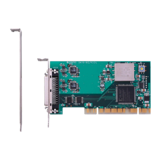
- Page 1 PC-HELPER High-Resolution Analog Output Board for Low Profile PCI 16ch DA16-16(LPCI)L DA16-8(LPCI)L User’s Guide CONTEC CO., LTD.
-
Page 2: Check Your Package
Check Your Package Thank you for purchasing the CONTEC product. The product consists of the items listed below. Check, with the following list, that your package is complete. If you discover damaged or missing items, contact your retailer. Product Configuration List - Board (One of the following) …1... -
Page 3: Copyright
All relevant issues have been considered in the preparation of this document. Should you notice an omission or any questionable item in this document, please feel free to notify CONTEC CO., LTD. Regardless of the foregoing statement, CONTEC assumes no responsibility for any errors that may appear in this document or for results obtained by the user as a result of using this product. -
Page 4: Table Of Contents
Table of Contents Check Your Package ........................... i Copyright ..............................ii Trademarks ..............................ii Table of Contents ............................iii BEFORE USING THE PRODUCT About the Board ............................1 Features ..............................1 Support Software ..........................2 Cable & Connector (Option) ......................3 Accessories (Option) .......................... - Page 5 Using the API-AIO(WDM) ........................ 17 Step4 Initializing the Software ........................ 19 Step 5 Checking Operations with the Diagnosis Program ..............21 What is the Diagnosis Program?...................... 21 Check Method ............................ 21 Using the Diagnosis Program ......................22 Setup Troubleshooting ..........................25 Symptoms and Actions ........................
- Page 6 Uninstalling the driver ........................60 ABOUT HARDWARE For detailed technical information ......................61 Hardware specification ..........................62 Block Diagram ............................66 Timing for Control Signal ........................68 Timing for Analog Output Control Signal ..................68 Control Signal Timings for Counter Timing for Counter Control Signal ........69 About Calibration .............................
- Page 7 DA16-16(LPCI)L, DA16-8(LPCI)L...
-
Page 8: Before Using The Product
1. Before Using the Product 1. Before Using the Product About the Board < DA16-16(LPCI)L > and < DA16-8(LPCI)L > is a PCI-compliant interface board that incorporates high-precision 16bit analog outputs, digital I/O(TTL level, 4 channels each), and a counter (32bit, 1 channel) function. -
Page 9: Support Software
API functions (DLL). Various sample programs such as Visual Basic and Visual C++, etc and diagnostic program *1useful for checking operation is provided. For more details on the supported OS, applicable language and new information, please visit the CONTEC’s Web site. -
Page 10: Cable & Connector (Option)
Screw Terminal Unit (M3 x 50P) EPD-50A *1 *2 *1 PCB50PS-0.5P or PCB50PS-1.5P optional cable is required separately. *2 “Spring-up” type terminal is used to prevent terminal screws from falling off. * Check the CONTEC’s Web site for more information on these options. DA16-16(LPCI)L, DA16-8(LPCI)L... -
Page 11: Customer Support
You can download updated driver software and differential files as well as sample programs available in several languages. Note! For product information Contact your retailer if you have any technical question about a CONTEC product or need its price, delivery time, or estimate information. Limited Three-Years Warranty CONTEC products are warranted by CONTEC CO., LTD. -
Page 12: Safety Precautions
1. Before Using the Product Safety Precautions Understand the following definitions and precautions to use the product safely. Safety Information This document provides safety information using the following symbols to prevent accidents resulting in injury or death and the destruction of equipment and resources. Understand the meanings of these labels to operate the equipment safely. -
Page 13: Handling Precautions
Even when using the product continuously, be sure to read the manual and understand the contents. Do not modify the product. CONTEC will bear no responsibility for any problems, etc., resulting from modifying this product. Regardless of the foregoing statements, CONTEC is not liable for any damages whatsoever (including damages for loss of business profits) arising out of the use or inability to use this CONTEC product or the information contained herein. -
Page 14: Environment
1. Before Using the Product Environment Use this product in the following environment. If used in an unauthorized environment, the product may overheat, malfunction, or cause a failure. Operating temperature 0 - 50°C Operating humidity 10 - 90%RH (No condensation) Corrosive gases None Floating dust particles... - Page 15 1. Before Using the Product DA16-16(LPCI)L, DA16-8(LPCI)L...
-
Page 16: Setup
2. Setup 2. Setup This chapter explains how to set up the board. What is Setup? Setup means a series of steps to take before the product can be used. Different steps are required for software and hardware. The setup procedure varies with the OS and applications used. Using the Board under Windows Using the Driver Library API-PAC(W32) This section describes the setup procedure to be performed before you can start developing application... -
Page 17: Using The Board Under An Os Other Than Windows
2. Setup Using the board under an OS other than Windows For using the board under Linux, see the following parts of this manual. This chapter Step 2 Setting the Hardware Chapter 3 External Connection Chapter 5 About Software Chapter 6 About Hardware For using the board under an OS other than Windows and Linux, see the following parts of this manual. -
Page 18: Step 1 Installing The Software
OS used, the basic procedure is the same. Which Driver to Use CONTEC has two analog I/O drivers: “API-AIO(WDM)” and “API-AIO(98/PC)”. API-AIO(WDM) is a new driver for analog I/O under Windows. This driver was developed to be easier to use and to provide additional functions above those provided by the previous API-AIO(98/PC) driver. -
Page 19: Starting The Install Program
2. Setup Starting the Install Program (1) Load the bundled disk [API-PAC(W32)] on your PC. (2) The API-PAC(W32) Installer window appears automatically. If the panel does not appear, run (drive letter):\AUTORUN.exe. (3) Click on the [Install Development or Execution Environment] button. CAUTION Before installing the software in Windows Vista, XP, Server 2003, 2000, log in as a user with administrator privileges. - Page 20 2. Setup Selecting API-AIO(WDM) (1) The following dialog box appears to select “Driver to install” and “Install option”, “Usage of driver library”. (2) Select the "Advanced Analog I/O driver". (3) Click on the [Install] button. Clicking the [API-AIO] button under the “Detail” displays detailed information about API- AIO(WDM) and API-AIO(98/PC).
-
Page 21: Step 2 Setting The Hardware
2. Setup Step 2 Setting the Hardware This section describes how to set this product and plug it on your PC. This product has some switches and jumper to be preset. Check the on-board switches and jumpers before plugging this product into an expansion slot. This product can be set up even with the factory defaults untouched. -
Page 22: Parts Of The Board And Factory Defaults
2. Setup Parts of the Board and Factory Defaults Figure 2.2. shows the names of major parts on the board. Note that the switch setting shown below is the factory default. - Interface connector (CN1) - Board ID setting switch BOARD ID (SW1) BOARD ID... -
Page 23: Plugging The Board
2. Setup Plugging the Board (1) Before plugging the board, shut down the system, unplug the power code of your PC. (2) Remove the cover from the PC so that the board can be mounted. (3) Plug the board into an expansion slot. (4) Attach the board bracket to the PC with a screw. -
Page 24: Step 3 Installing The Hardware
2. Setup Step 3 Installing the Hardware Windows needs to detect the I/O address and interrupt used by the board. This is called hardware installation. When using more than one board, install the boards one at a time and do not install the next board until setup is complete for the previous board. - Page 25 2. Setup (2) Specify that folder on the bundled disk which contains the setup information file (INF) to register the board. * The name of the board you have just added is displayed. - DA16-16(LPCI)L - DA16-8(LPCI)L Source folder The setup information file (INF) is contained in the following folder on the bundled disk. \INF\WDM\AIO \INF\WDM\AIO You have now finished installing the software.
-
Page 26: Step4 Initializing The Software
- DA16-16(LPCI)L - DA16-8(LPCI)L (2) The installed hardware appears under the CONTEC Devices node. Open the CONTEC Devices node and select the device you want to setup (the device name should appear highlighted). Click [Properties]. DA16-16(LPCI)L, DA16-8(LPCI)L... - Page 27 2. Setup (3) The property page for the device opens. Enter the device name in the common settings tab page and then click [OK]. The device name you set here is used later when programming. * The name of the board you have just added is displayed.
-
Page 28: Step 5 Checking Operations With The Diagnosis Program
2. Setup Step 5 Checking Operations with the Diagnosis Program Use the diagnosis program to check that the board and driver software work normally, thereby you can confirm that they have been set up correctly. What is the Diagnosis Program? The diagnosis program diagnoses the states of the board and driver software. -
Page 29: Using The Diagnosis Program
2. Setup Using the Diagnosis Program Starting the Diagnosis Program Click the [Diagnosis] button on the device property page to start the diagnosis program. * The name of the board you have just added is displayed. - DA16-16(LPCI)L - DA16-8(LPCI)L DA16-16(LPCI)L, DA16-8(LPCI)L... - Page 30 2. Setup Analog output You can select the desired output channel and output range from the lists. You can set the output data to DC (constant voltage), sine wave, or square wave. Digital I/O The upper row of circular lamps indicates the digital input states. Red indicates the bit is ON and brown indicates OFF.
- Page 31 2. Setup Diagnosis Report (1) The diagnosis report saves detailed data, including the device settings and settings for each channel, to a text file and displays the file for you to view. Clicking [Diagnosis Report] prompts you to specify where to save the report text file. * The name of the board you have just added is displayed.
-
Page 32: Setup Troubleshooting
2. Setup Setup Troubleshooting Symptoms and Actions Data output does not operate correctly Run the diagnosis program to check that the device is registered and whether any initialization errors have occurred. Is there a problem with the device settings, wiring, or similar? Check the output range setting. The board works with the Diagnosis Program but not with an application. - Page 33 2. Setup DA16-16(LPCI)L, DA16-8(LPCI)L...
-
Page 34: External Connection
3. External Connection 3. External Connection This chapter describes the interface connectors on the product and the external I/O circuits. Check the information available here when connecting an external device. How to connect the connectors Connector shape To connect an external device to this product, plug the cable from the device into the interface connector (CN1) shown below. -
Page 35: Connector Pin Assignment
3. External Connection Connector Pin Assignment Pin Assignments of DA16-16(LPCI)L Interface Connector(CN1) Analog O utput 02 AO 02 AO 00 Analog O utput 00 Analog Ground ( for AO ) AGND AGND Analog Ground ( for AO ) Analog O utput 03 AO 03 AO 01 Analog O utput 01... - Page 36 3. External Connection Pin Assignments of DA16-8(LPCI)L Interface Connector Analog O utput 02 AO 02 AO 00 Analog O utput 00 Analog Ground ( for Analog Ground ( for AGND AGND AO ) AO ) Analog O utput 03 AO 03 AO 01 Analog O utput 01 Analog Ground ( for...
-
Page 37: Connecting The Analog Output Signal
3. External Connection Connecting the Analog Output Signal This section shows how to connect the analog output signal by using a flat cable or a shielded cable. The following figure shows an example of flat cable connection. Connect the signal source and ground to the CN1 analog output. BOARD Cable Target... -
Page 38: Connecting The Digital I/O, Counter And Control Signal
3. External Connection Connecting the Digital I/O, Counter and Control Signal The following sections show examples of how to connect digital I/O signals, counter I/O signals, and other control I/O signals (external trigger input signals, sampling clock input signals, etc.). All the digital I/O signals and control signals are TTL level signals. - Page 39 3. External Connection DA16-16(LPCI)L, DA16-8(LPCI)L...
-
Page 40: Functions
4. Functions 4. Functions This chapter describes the different functions that can be implemented using the hardware and driver together. Unless stated otherwise, the driver is assumed to be API-AIO(WDM). Analog Output Function This product converts digital data to analog signals according to the resolution. You can set a variety of conditions for analog output, including the output channel, sampling period, and sampling start/stop conditions. -
Page 41: Setting The Conversion Conditions
4. Functions 1. Setting the Conversion Conditions First, set the conditions for executing analog output. Resolution "Resolution" signifies the number of bits used by an analog output device to represent analog signals. The higher the resolution, the more finely the voltage range is segmented, allowing the device to convert digital values to analog equivalents more precisely. - Page 42 4. Functions Output data Output data = ((Voltage – Min. range value) x Resolution) / (Max. range value – Min. range value) The value of resolution for the 16bit device is 65536. The table below shows the relationship between output data and voltage in the ±10-V range. Voltage Output data(16bit) +9.99970V...
- Page 43 4. Functions Data transfer method A device buffer mode is available, which uses the device's or driver's conversion data storage memory. Device buffer mode The application output data is first stored in the device buffer (memory on the device itself or in the driver).
- Page 44 4. Functions Memory format This product uses device buffer transfer mode; it does not require software setup of the memory format. Device buffer mode FIFO format Use FIFO format if you wish to output a continuous arbitrary analog output like that shown below. When using FIFO format, writing of conversion data to memory is always performed from after the most recent data and DA conversion is performed on the oldest data in memory.
- Page 45 4. Functions Ring format Use ring format if you wish to output a repeated pattern like that shown below. When using ring format, write the data for one complete cycle of the output waveform before starting operation. You cannot write to the memory during its operation of analog output. DA conversion data is output continuously in the sequence in which the ring format data is stored.
- Page 46 4. Functions Repeat You can specify a repeat count to perform sampling for a specified number of times. Memory must be set to ring format if a number of repetitions is to be specified. (The number of repetitions cannot be specified for FIFO memory format.) The number of repetitions is set by software and sampling is repeated for the specified number of times.
- Page 47 4. Functions Procedure for RING format When using ring format, a ring memory area large enough for the data to be set is reserved. Data cannot be modified during DA conversion. Clock The sampling clock controls the sampling frequency. You can select either the internal sampling clock, or external sampling clock.
- Page 48 4. Functions Stop Condition The condition for controlling the stop of sampling can be selected from among the last sampling count, an external trigger, and software abort. This product stops sampling whenever an error occurs irrespective of the stop condition setting. Last sampling count This product stops sampling after storing input data to memory for the specified number of times of sampling.
-
Page 49: Starting/Stopping Operation
4. Functions 2. Starting/Stopping Operation Analog output operation is started by a software command (the analog output start command). Similarly, you can stop analog output at any time using a software command (the analog output stop command). 3. Monitoring the Status and Acquiring Data You can use a software command to check the status of analog output operation and of the output data stored in memory. -
Page 50: Reset
4. Functions 4.Reset Various states can be reset by executing the following reset commands: Status This command resets the sampling clock error status and AD conversion error status. Memory This can only be used when the transfer mode is set to device buffer mode. This command resets the following memory related states. -
Page 51: Counter Function
4. Functions Counter Function 1. Setting the Operating Conditions This specifies the conditions for counter operation. Operating conditions The basic operation of the counter is to count an external input signal. The counter includes a function to detect a count match and perform a specified operation when the current count value reaches a preset count value. -
Page 52: Starting/Stopping Operation
4. Functions Event The event function notifies the application when something occurs on the device. The following events can be used as required. Compare count match event This event is triggered when a compare match occurs on the counter. Count overrun event This event is triggered when a counter overrun occurs. -
Page 53: Reset
4. Functions 4.Reset Various states can be reset by executing the following reset commands: Counter reset Resets the counter. This restores the counter to its state after power on. Status Resets the compare count match status and overrun status. DA16-16(LPCI)L, DA16-8(LPCI)L... -
Page 54: Digital Input Function
4. Functions Digital Input Function Input bit Individual digital input points are called input bits. When the number of input points of a device is 4, the bits are determined as bit 0 - bit 3. Bit 0 Bit 3 Bit 2 Bit 1 Input in Bits... -
Page 55: Digital Output Function
4. Functions Digital Output Function Output bit Individual digital output points are called output bits. When the number of output points of a device is 4, the bits are determined as bit 0 - bit 3. Bit 0 Bit 3 Bit 2 Bit 1 Output in Bits... -
Page 56: About Software
5. About Software 5. About Software Bundled disk Directory Structure |– Autorun.exe Installer Main Window | Readmej.html Version information on each API-TOOL (Japanese) | Readmeu.html Version information on each API-TOOL (English) |–––APIPAC Each installer |––AIO |––DISK1 |––DISK2 |––…… |––DISKN |––AioWdm |––CNT |––DIO |––……... -
Page 57: About Software For Windows
“Function Reference”, “Sample Programs”, “Tutorial”, “FAQs”and “Troubleshooting”. Use them for program development and troubleshooting. Accessing the Help File (1) Click on the [Start] button on the Windows taskbar. (2) From the Start Menu, select “Programs” – “CONTEC API-PAC(W32)” – “AIOWDM” – “API-AIO(WDM) HELP” to display help information. DA16-16(LPCI)L, DA16-8(LPCI)L... -
Page 58: Using Sample Programs
The sample programs are stored in \Program Files\CONTEC\API-PAC(W32)\AIOWDM\Samples. Running a Sample Program (1) Click on the [Start] button on the Windows taskbar. (2) From the Start Menu, select “Programs” – “CONTEC API-PAC(W32)” – “AIOWDM” – “SAMPLE…”. (3) A sample program is invoked. - Page 59 5. About Software Sample Programs - Examples Analog input Simple sample program - SingleAi Perform single analog input from specified channel - MultiAi Perform single analog input from multiple channels Device buffer - Ai Perform standard analog input using a FIFO buffer - AiPoll Perform standard analog input by polling - AiEx...
-
Page 60: Usage Of Utility Program
5. About Software Usage of Utility Program Program for Measurement of Function Execution Speed The execution time of some main functions can be measured in a function execution speed measurement program. To use a function execution speed measurement program, click the [execution time measurement] button in the diagnostic program. - Page 61 5. About Software Analog Output Measurement Tool It is an analog output measurement utility to carry out infinity sample in the FIFO memory. Once the conversion data of memory accumulates to a certain quantity, the event occurs and new output data is added.
- Page 62 5. About Software Procedure (1) Chose the device name of the device to be used from the upper left combo box, and click the setting button. (2) The conversion conditions are set on the screen of the setting analog output. Once an output is done at the sampling frequency specified as data setting sampling frequency, an event occurs and data will be added.
-
Page 63: Uninstalling The Driver Libraries
[Device Manager] tab. (You can also open Device Manager by right clicking on My Computer and selecting Properties.) 2. All of the hardware that uses the API-TOOL(WDM) driver is registered under the CONTEC Devices tree. Open the device tree, select the hardware to uninstall, and then right-click the hardware. - Page 64 < Uninstall the device driver > Use [My Computer] - [Control Panel] - [Add and Remove Programs] to uninstall the device driver. Select [Windows driver package - CONTEC (****)] and then click [Change/Remove]. * "***" contains the driver category name (caio, ccnt, cdio, csmc, etc.).
- Page 65 < Uninstall the development environment > Use [My Computer] - [Control Panel] - [Add or Remove Programs] to uninstall the development environment. Select [CONTEC API-***(WDM) VerX.XX (development environment)] and then click [Change/Remove]. * "***" contains the driver category name (AIO, CNT, DIO, SMC, etc.).
-
Page 66: About Software For Linux
# mount /dev/cdrom /mnt/cdrom Mount the bundled disk. # cp /mnt/cdrom/linux/aio/caioXXX.tgz ./ Copy the compressed file. # tar xvfz caioXXX.tgz Decompress the compressed file....# cd contec/caio # make Compile the file....# make install Install....# cd config # ./config... -
Page 67: Accessing The Help File
Sample programs for each language are contained in the contec/caio/samples directory. For compiling them, refer to the manual for the desired language. Uninstalling the driver To uninstall the driver, use the uninstall shell script contained in the contec/caio directory. For details, check the contents of the script. DA16-16(LPCI)L, DA16-8(LPCI)L... -
Page 68: About Hardware
This chapter provides hardware specifications and hardware-related supplementary information. For detailed technical information For further detailed technical information ("Technical Reference" including the information such as an I/O map, configuration register, etc.), visit the Contec's web site to call for it. DA16-16(LPCI)L, DA16-8(LPCI)L... -
Page 69: Hardware Specification
6. About Hardware Hardware specification DA16-16(LPCI)L Table 6.1. Specification < DA16-16(LPCI)L > Item Specification Analog output Isolated specification Non-isolation Number of output channels 16 channels Bipolar ±10V Output range Absolute max. output ±3mA currency Output impedance 1 Ω or less Resolution 16bit Non-Linearity error *1... - Page 70 6. About Hardware Board Dimensions 121.69(L) [mm] The standard outside dimension(L) is the distance from the end of the board to the outer surface of the slot cover. DA16-16(LPCI)L, DA16-8(LPCI)L...
- Page 71 6. About Hardware DA16-8(LPCI)L Table 6.2. Specification < DA16-8(LPCI)L > Item Specification Analog output Isolated specification Non-isolation Number of output channels 8 channels Output range Bipolar ±10V Absolute max. output ±3mA currency Output impedance 1 Ω or less Resolution 16bit Non-Linearity error *1 ±5LSB Conversion speed...
- Page 72 6. About Hardware Board Dimensions 121.69(L) [mm] The standard outside dimension(L) is the distance from the end of the board to the outer s urface of the slot cover. DA16-16(LPCI)L, DA16-8(LPCI)L...
-
Page 73: Block Diagram
6. About Hardware Block Diagram Figure 6.1 - 6.2 is a circuit block diagram of this product. DA16-16(LPCI)L 4 Digital Input / 4 Digital Output 16 Analog Outputs External Trigger Inputs Counter Input / Output Converter Converter Converter Converter FPGA DC/DC converter PCI Bus... - Page 74 6. About Hardware DA16-8(LPCI)L 4 Digital Input / 4 Digital Output 8 Analog Outputs External Trigger Inputs Counter Input / Output Converter Converter Converter Converter FPGA DC/DC converter PCI Bus Figure 6.2. Block Diagram < DA16-8(LPCI)L > DA16-16(LPCI)L, DA16-8(LPCI)L...
-
Page 75: Timing For Control Signal
6. About Hardware Timing for Control Signal Timing for Analog Output Control Signal Figures 6.3, 6.4, 6.5, and Table 6.3 shows the timing for analog output control signal. External Smapling Clock Input Conversion start Figure 6.3. Timing for External Sampling Clock (Analog output) External Smapling Start Trigger Input Figure 6.4. -
Page 76: Control Signal Timings For Counter Timing For Counter Control Signal
6. About Hardware Control Signal Timings for Counter Timing for Counter Control Signal Figures 6.6, 6.7, and Table 6.4 shows the timing for counter I/O signal. Counter Up Pulse Input Figure 6.6. Timing for Counter Input Signal Counter Compair Output Figure 6.7. -
Page 77: About Calibration
6. About Hardware About Calibration Although this product is calibrated before shipping, you can use the calibration program to calibrate analog input and output yourself. Starting the calibration program Click the [Calibration] button on the property page for the device to start the calibration program. * The name of the board you have just added is displayed. - Page 79 December 2017 Edition 3-9-31, Himesato, Nishiyodogawa-ku, Osaka 555-0025, Japan https://www.contec.com/ No part of this document may be copied or reproduced in any form by any means without prior written consent of CONTEC CO., LTD. [12252017] [03102006] Management No. A-51-123 [12252017_rev5] Parts No.