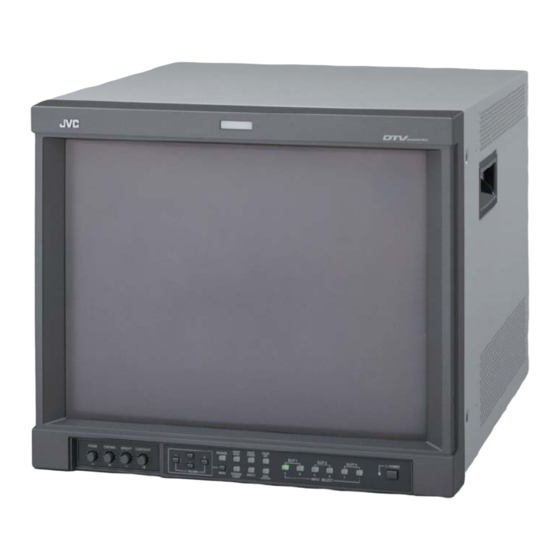
JVC DT-V1710CG Instructions Manual
Multi-format monitor
Hide thumbs
Also See for DT-V1710CG:
- Instructions manual (228 pages) ,
- Instructions manual (64 pages) ,
- Service manual (77 pages)

Related Manuals for JVC DT-V1710CG


Summary of Contents for JVC DT-V1710CG
- Page 1 MULTI-FORMAT MONITOR DT-V1710CG INSTRUCTIONS The supplied wide mask is attached to the monitor in the illustration on the right. LCT2014-001A...
-
Page 2: Safety Precautions
Thank you for purchasing this JVC Multi-Format Monitor. Before using it, read and follow all instructions carefully to take full advantage of the monitor’s capabilities. SAFETY PRECAUTIONS In order to prevent any fatal accidents caused by misoperation or mishandling of the monitor, be fully aware of all the following precautions. -
Page 3: Table Of Contents
CONTENTS SAFETY PRECAUTIONS ................ 2 Controls and Features ................4 Front View ....................4 Rear/Side View..................6 Input Card: Optional ................7 Preparation ................... 10 Basic Menu Operations ............... 11 How to Use MAIN MENU ..............13 How to Use SET-UP MENU ..............15 How to Use the External Control ............ -
Page 4: Controls And Features
Controls and Features 7Front View 11 12 13 14 10 15 16 17 1 Tally lamp 7 MUTING button This lamp is controlled by the tally function of Pressing this button mutes the output sound. the MAKE/TRIGGER terminal. • To cancel “MUTING ON” (no sound), press MUTING button again, or press the VOLUME “–”... - Page 5 q DEGAUSS button/lamp u AREA MARKER button/lamp Performs degaussing. Turns the AREA MARKER function ON/OFF. • When degaussing is completed, the lamp goes off. • AREA MARKER function includes MARKER SELECT, ZOOM, ASPECT SELECT, and SAFETY MARKER w UNDER SCAN button/lamp functions.
-
Page 6: Rear/Side View
Controls and Features (cont.) 7Rear/Side View <Rear Panel> <Side Panel> 1 REMOTE (external control) terminals 3 Main power switch Terminals for controlling the monitor by an Turns on and off the main power. external control. • I : on : off ☞... -
Page 7: Input Card: Optional
Specifications are subject to change without notice. For the latest information of the input cards, contact your dealer. 7Input Card: Optional COMPONENT/RGB INPUT CARD (IF-C01COMG) 1 Component/RGB signal input/output terminals Input (IN) and output (OUT) terminals for component (color difference) or RGB signals. Select component signal: /B-Y press INPUT SELECT A (SLOT1)/C (SLOT2)/E (SLOT3) buttons. - Page 8 Controls and Features (cont.) 7Input Card: Optional (cont.) HD SDI INPUT CARD (IF-C12HSDG) Compliant with EMBEDDED AUDIO 1 HD SDI signal input/output terminals (HD SDI 1, HD SDI 2) Input (IN) and output (OUT) terminals for the HD SDI signal. This card is also compatible with EMBEDDED AUDIO signals with E.AUDIO HD SDI 1...
- Page 9 Specifications are subject to change without notice. For the latest information of the input cards, contact your dealer. HD SDI INPUT CARD (IF-C21HSDG/IF-C51HSDG) Compliant with EMBEDDED AUDIO and AUTO INPUT (IF-C51HSDG is equipped with the AUDIO LEVEL METER function) 1 HD SDI signal input/output terminals (HD SDI 1) Input (IN) and output (OUT) terminals for the HD SDI signal.
-
Page 10: Preparation
Preparation 7Installing the Input Card 7Attaching the Power Cord Holder Optional input cards are necessary to use the functions of this monitor. Before mounting the monitor or • The provided Power Cord Holder prevents accidental connecting other equipment to the monitor, be sure to disconnection of the AC power cord from the AC inlet. -
Page 11: Basic Menu Operations
Basic Menu Operations 7About the Menu Screens This monitor features MAIN MENU which contains the functions normally used and SET-UP MENU which contains the initial settings of the monitor. MAIN MENU Items Functions Displays APERTURE CONTROL Compensates the frequency characteristics of the luminance signal of a video signal. SLOT CONDITION Displays the status of the input cards installed in each of the input card slots. - Page 12 Basic Menu Operations (cont.) 7Displaying the Menu 7About “ sub menu” Screens When “ sub menu” is displayed in the menu, only selected item in that menu can be displayed and To display MAIN MENU adjusted. This allows you to make adjustments while looking at the actual screen.
-
Page 13: How To Use Main Menu
How to Use MAIN MENU 7MAIN MENU Screens MAIN MENU Setting Items Press ☞ pages 12, 14 Adjust with buttons. About “ sub menu” and “reset,” ☞ page 12 NOTE: • Some items may not appear on the menu depending on the input or the input signal. Those items are not available to use. - Page 14 How to Use MAIN MENU (cont.) 7 SAFETY MARKER/R-SAFETY MARKER sub menu POSI. Displays dotted lines to indicate the areas Selects the display position of the sub menu corresponding to 80%, 88%, or 90% of the screen superimposed on the screen. size (the aspect ratio setting in “ASPECT SELECT/ ☞...
-
Page 15: How To Use Set-Up Menu
How to Use SET-UP MENU 7SET-UP MENU Screens SET-UP MENU Setting Items Press ☞ page 20 Adjust with buttons. About “ sub menu” and “reset,” ☞ page 12 * To go back to the previous menu, press MENU. NOTE: • Some items may not appear on the menu depending on the input or the input signal. Those items are not available to use. - Page 16 How to Use SET-UP MENU (cont.) 7Functions and Adjustment Range of Items NOTES: FUNCTION SETTING • Functions only when HD SDI input card or SD input Selects the control systems card compatible with AUTO INPUT is used. for the COLOR SYSTEM, •...
- Page 17 7 REMOTE SYSTEM PICTURE SUB ADJ. Sets the MAKE/TRIGGER terminal. Controls the approximate • MAKE (make contact)/TRG. (trigger contact) adjustment of the video ☞ “How to Use the MAKE/TRIGGER Terminal” on page control level when the video adjustment knob is adjusted 7 E.
- Page 18 How to Use SET-UP MENU (cont.) COLOR TEMP./BAL. SIZE/POSI. ADJ. Sets or adjusts the color Adjusts the size and temperature and white position of the picture. balance. • Can also be used to adjust the zoomed picture size. 7 H. SIZE NOTE: Adjusts the horizontal screen size.
- Page 19 DISTORTION ADJ. STATUS DISPLAY Compensates the picture Sets the items related to the distortion and tilt. display screens, such as the status display or the AUDIO LEVEL METER display (when an input card compatible with AUDIO LEVEL METER is installed). •...
- Page 20 How to Use SET-UP MENU (cont.) 7 BAR BRIGHTNESS STATUS DISPLAY (cont.) Selects the brightness of the AUDIO LEVEL 7 1080/1035 METER display. HIGH: Brighter When the component signal is input, the monitor LOW: Darker does not automatically discriminate the 1080/60i 7 REFERENCE LEVEL signal from the 1035/60i signal.
-
Page 21: How To Use The External Control
How to Use the External Control 7About the External Control The Multi-Format Monitor has two external control terminals. One is the MAKE/TRIGGER terminal, which allows the monitor to be controlled by the MAKE (make contact) or TRG. (trigger) method selected in the function setting. MAKE (make contact) system: Controls the function by short-circuiting the corresponding pin terminal to the GND pin terminal, or disconnecting (opening) it. - Page 22 How to Use the External Control (cont.) 7How to Use the RS-485 Terminal You can control the monitor from your PC via the RS-485 terminal. For details on operating the monitor from the PC, consult the service center. 1. Cable Prepare a straight cable with a D-sub connector (9-pin, male) and a D-sub connector (9-pin, male).
-
Page 23: Troubleshooting
Troubleshooting Solutions to common problems related to your monitor are described here. If none of the solutions presented here solve the problem, unplug the monitor and consult a JVC-authorized dealer or service center for assistance. Reference Problems Points to be checked... - Page 24 Troubleshooting (cont.) Reference Problems Points to be checked Measures (Remedy) pages Has the picture position, size, Adjust the picture size (H. SIZE, V. SIZE) or Wrong picture distortion, or tilt been changed? position (H. POSITION, V. POSITION) in “SIZE/ position, wrong POSI.
-
Page 25: Self-Check Indications
7Self-check Indications When the screen goes blank, and one or more of the INPUT SELECT A through F lamps on the front control panel start flashing... This monitor has a self-check function, which allows it to detect malfunctions and alert you. This makes troubleshooting easier. -
Page 26: Specifications
Specifications DT-V1710CG Model Multi-Format Monitor Type 17" measured diagonally Picture Tube Width: 330 mm Effective Screen Size Height: 250 mm Diagonal: 410 mm H : 15 kHz/27 kHz – 45 kHz Scanning Frequency V : 50 Hz – 80 Hz Component: 25 MHz (–3 dB) - Page 27 7Dimensions Unit : mm Front View Front View Side View (with the wide mask attached) 466.5 336 * 331 * Asterisks(*) are used to indicate front panel dimensions. 7Compliant Signal Format of each Input Card Specifications are subject to change without notice. Contact your dealer for the latest information of the input cards. Input signal IF-C01PNG IF-C01COMG IF-C21SD1G IF-C51SD1G IF-C12HSDG IF-C21HSDG IF-C51HSDG IF-C61HSDG...
- Page 28 © 2006 Victor Company of Japan, Limited 0106MKH-MW-VP...